For these reasons, this paper studies the synthesis of InP nanocrystals (NCs) and QDs using aminophosphine as phosphine precursor and steel-based microreactor system. Application of microreactor in the process showed the possibility of continuous synthesis of InP NCs and QDs, as well as simple tuning of 1st excitonic peak of the products by the variables such as flow rate, temperature, halide exchange of indium precursor and dodecanethiol (DDT) addition. Synthesis of InP@ZnS Core@Shell structured QDs is also performed in microreactor, showing similar PLQY of the product compared to that of the QDs produced from a batch reactor.
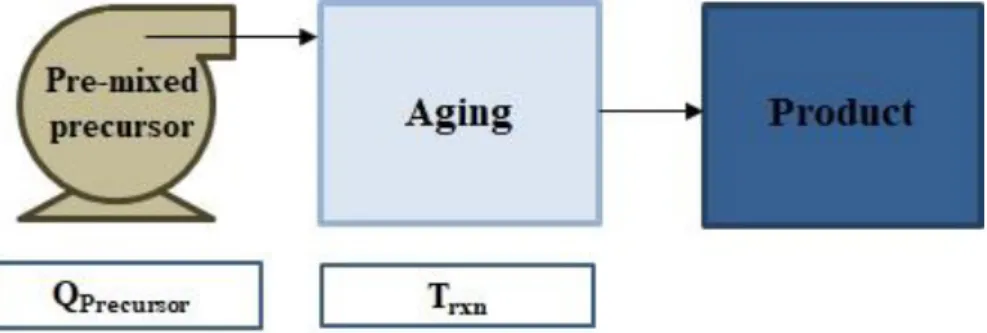
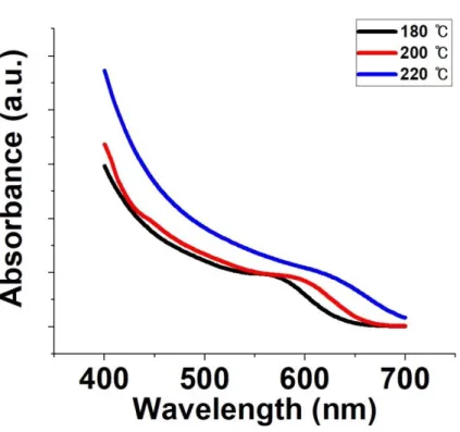
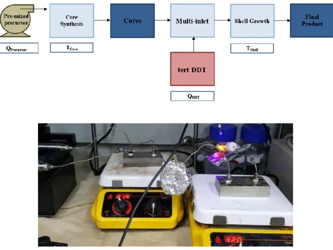
Schematics and images of InP NC synthesis microfluidic reactor system and reactor structure. Absorption plot of InP NCs synthesized from different indium precursors (InX3, X=Cl, Br, I), with fixed temperature and flow rate 180 ℃ and 50 μl/min. Absorption plot of InP NCs synthesized from tert-DDT added precursor, with fixed temperature and flow rate of 200 ℃ and 20 μl/min.
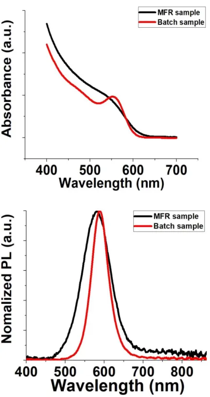
Absorption and PL spectra of InP@ZnS Core@Shell QDs from microfluidic reactor and conventional batch reactor. UV emission of the products from the microfluidic reactor and the conventional batch reactor (left: MFR-based products, right: batch-based products).
Definition of microfluidic reactor
In terms of productivity, the small volume of the microfluidic reactor can be a disadvantage due to its low capacity. However, it is possible to increase the throughput of microfluidic reactors by increasing the flow rate by changing the reactor materials and parallelizing multiple reactors, which is called scaling.
![Figure 1. Schematic of multi-microchannel droplet reactor [12]](https://thumb-ap.123doks.com/thumbv2/123dokinfo/10487792.0/15.892.132.760.443.638/figure-1-schematic-multi-microchannel-droplet-reactor-12.webp)
History of microfluidic reactor
Fabrication of microfluidic reactor
Application of microfluidic reactor on nanocrystal synthesis
Synthesis of InP nanocrystals via microfluidic reactor
Experimental session
- Overall setup of microfluidic reactor system
- Chemicals
- Preparation of stock solutions
- Characterizations
The shape of the channels is sinusoidal and each reactor parts are physically fastened with bolts. Reagents are injected into the system using Harvard Apparatus PHD 2000 HVP Programmable Syringe Pump 70-2023 and 20 ml Harvard Apparatus steel syringes. The dimensions of each reactor plates are 100 X 55 X 12 mm, since the size of the top and bottom plates is the same.
To prevent leakage due to physical attachment of the plates with bolts, a gasket made of several layers of Teflon tape is added. The temperature control of the reactor system is performed by a feedback controller, which probe is added between each of the reactor plates with the gasket. It therefore proves that the reactor can be recycled by cleaning with pure ODE.
The sinusoidal shape is commonly used in the design of microreactor channels, as it can increase the surface-to-volume ratio of the reactor to increase heat transfer. Indium(Ⅲ) chloride (InCl3), zinc chloride (ZnCl2), Oleylamine (97%) (OAm), tris(diethylamino)phosphine (DEAP), tert-dodecanethiol, and 1-Octadecene (ODE) were purchased from Sigma-Aldrich. After the temperature of the mixture drops to RT, 2.76 ml of DEAP is injected under inert conditions.
UV-Vis absorption graphs of InP NCs are characterized by Shimadzu UV-1800 UV-VIS spectrophotometer.
Result and discussion
- Synthesis of InP NCs at various temperature ranges
- Synthesis of InP NCs at various flow rates
- Synthesis of InP NCs with halide exchange of indium precursor
- Synthesis of InP NCs with addition of tert-dodecanethiol
- Comparison between MFR-based InP NCs and batch-based InP NCs
- Characterizations
From those results, it is clear that the position of 1st exciton peak is affected by temperature and flow rate. In the same temperature, 1st exciton peaks of the products are broadened as the flow rate increases. According to the results, changing temperature to control the position of 1st exciton peak is more effective than changing flow rate in the synthesis of InP NCs by the microfluidic reactor system.
The reason is, as both temperature and flow rate increase, the position and shape of the peak is more dependent on the change in temperature. In short, band gap of InP NCs synthesized by the reactor system can be easily controlled by changing temperature and flow rate of the system. The advantage of microfluidic reactor over the batch reactor is the synthesis of InP NCs with different absorption peaks with only the change of the temperature and flow rate, while maintaining the continuous process.
The first exciton peak of InP NCs synthesized using InI3 is measured at 450 nm and the peak of InP NCs synthesized using InBr3 is measured at 500 nm. The results show a significant shift of the peak compared to that of changing temperature and flow rate. According to previous work in the literature by Tessier et al., the surface reaction rates change when halogens are adsorbed on the surface of InP NCs, which resulted from the interaction between InP NCs and the halogen or steric effect.
Therefore, the surface reaction rate decreases and eventually stops the growth of InP NCs. For these reasons, halide exchange affects the final size of InP NCs, which is related to the 1st exciton peak. DDT, as a strong Lewis base, also disrupts InP nucleation, causing smaller nuclei to form.
From this, InP NCs with shorter absorption wavelength can be synthesized from the addition of DDT.[53]. Also, the temperature and flow rate conditions of the reactor system are adjusted due to the previously mentioned reasons. We can assume that the effect of tert-DDT limits the size of the InP NCs to some extent, leading to a decrease in the size distribution.
Through the spectrum, the existence of the InP peak indicates that the products contain the InP component. In the TEM images, we can detect the crystal structure of the InP NCs, which means that the products created using the current microfluidic reactor system are the same as those of the batch system.
Conclusions
Synthesis of InP@ZnS Core@Shell-structured quantum dots via microfluidic
Experimental session
- Overall setup of microfluidic reactor system
- Chemicals
- Stock solution for core synthesis
- Characterizations
Reagents for core and shell synthesis are injected into the system using Harvard Apparatus PHD 2000 HVP Programmable Syringe Pump 70-2023 and 20 ml Harvard Apparatus steel syringes. The shape of channels is sinusoidal, which is the same as the reactor for NC synthesis. Reasons for the design of the channel shape in the reactors are similar to those of the design of the NC synthesis part.
Result and discussion
- Synthesis of InP@ZnS Core@Shell QDs and comparison between MFR samples and batch
- Characterizations
Through the spectrum, the existence of InP and ZnS peak tells that the products contain the component of InP@ZnS QDs. In TEM images, we can detect the crystal structure of InP@ZnS QDs, which proves that the products of the microfluidic reactor system are the same as those of the batch system. In this chapter, synthesis of InP@ZnS core@shell structured QDs is shown using versatile steel reactor and aminophosphine and tert-DDT as phosphine precursor for InP Cores and shell growth material.
Also, detection of InP and ZnS peaks in XRD spectra shows that the products mainly consist of InP@ZnS QDs. This thesis studied the synthesis of aminophosphine-based InP NCs and InP@ZnS core@shell structure QDs using versatile steel reactor system. For the synthesis of InP NCs using the reactor system, the effects of temperature and flow rate on the response and trend of the products are investigated.
For the synthesis of InP@ZnS core@shell structured QDs, the results demonstrate the feasibility of a simple process based on microfluidic reactors that integrates the entire processes of core synthesis and shell growth in one system. Wan, Zhen; Tu, Shan-tung; Yuan, Wei-Kang; Wang, Zhiming M. Continuous Synthesis of Full-Color Emitting Core/Shell Quantum Dots via Microreaction. Kang, Dongseok; Young Jeon, Duk Synthesis of ZnSe quantum dots using a continuous-flow microreactor and their white emission through energy transfer.
Marre, Samuel; Park, Jongnam; Rempel, Jane; Guan, Juan; Bawendi, Moungi G.; Jensen, Klavs F. Supercritical Continuous-Microflow Synthesis of Narrow Size Distribution Quantum Dots. Ju Yeon, Woo; Chang-Soo, Han Sequential and Large-Scale Synthesis of InP/ZnS Quantum Dots in a Hybrid Reactor and Its Application to White LEDs. Danek, Michal; Jensen, Klavs F.; Murray, Chris B.; Bawendi, Moungi G. Synthesis of Light-Thin Film CdSe/ZnSe Quantum Dot Composites Using CdSe Quantum Dots Passivated with an Overlayer of ZnSe.
CdSe)ZnS Core−Shell Quantum Dots: Synthesis and Characterization of a Size Series of High Luminosity Nanocrystallites. Tessier, Michael D.; Dupont, Dorian; De Nolf, Kim; De Roo, Jonathan; Pulat, Zeger Economical and size-tunable synthesis of InP/ZnE (E = S, Se) colloidal quantum dots. Li, Liang; Reiss, Peter One-pot synthesis of highly luminescent InP/ZnS nanocrystals without precursor injection.
Tessier, Michael D.; De Nolf, Kim; Dupont, Dorian; Sinnaeve, Davy; De Roo, Jonathan; Hens, Zeger Aminophosphines: A dual role in the synthesis of colloidal indium phosphide quantum dots. Andreas, Holländer Large-scale synthesis of high-quality InP quantum dots in a continuous flow reactor under supercritical conditions.
![Figure 2. Photograph of steel-based multichannel droplet reactor [20]](https://thumb-ap.123doks.com/thumbv2/123dokinfo/10487792.0/18.892.290.606.456.675/figure-photograph-steel-based-multichannel-droplet-reactor-20.webp)
![Figure 3. A photograph of the ten-layer, pile-up glass microreactor [22]](https://thumb-ap.123doks.com/thumbv2/123dokinfo/10487792.0/19.892.236.661.465.658/figure-3-photograph-layer-pile-glass-microreactor-22.webp)
![Figure 5. a) A scheme depicting the fabrication process of the AFFD. b) An image of the final AFFD [27]](https://thumb-ap.123doks.com/thumbv2/123dokinfo/10487792.0/21.892.228.664.298.837/figure-scheme-depicting-fabrication-process-affd-image-final.webp)
![Figure 6. Schematic of the microfluidic reaction system for the continuous synthesis of CdSe/ZnS and CdS/ZnS NCs [28]](https://thumb-ap.123doks.com/thumbv2/123dokinfo/10487792.0/23.892.140.765.479.681/figure-schematic-microfluidic-reaction-continuous-synthesis-cdse-zns.webp)
![Figure 8. Three-stage high-temperature and high-pressure microfluidic system for synthesis of InP NCs a) mixing stage, b) aging stage c) sequential injection stage [9]](https://thumb-ap.123doks.com/thumbv2/123dokinfo/10487792.0/25.892.185.705.374.713/figure-temperature-pressure-microfluidic-synthesis-mixing-sequential-injection.webp)
![Figure 9. Schematic of a hybrid-flow reactor for synthesis of InP@ZnS QDs [35]](https://thumb-ap.123doks.com/thumbv2/123dokinfo/10487792.0/26.892.133.739.427.673/figure-schematic-hybrid-flow-reactor-synthesis-inp-zns.webp)

