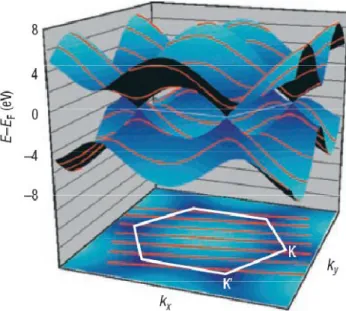
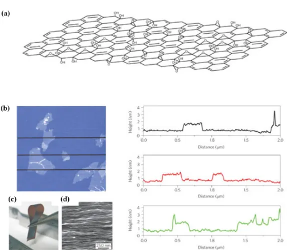
The relationship of these lines to the band structure of graphene determines the electronic structure of the nanotube. A scanning electron microscope image of the cross-section of the graphene oxide paper, showing layered structure. Characterization of the GO/metal hybrid films. a) SEM image and optical image (inset) of a bare FTO substrate.
The two-bilayer GO film on FTO was immersed in H2PtCl6 solution for 30 min, dried with N2 gas, and annealed at 550 oC. d) SEM image and optical image (inset) of the GO/Au hybrid film on FTO. The two-bilayer GO film on FTO was immersed in AuCl3 solution for 30 min, dried with N2 gas, and annealed at 550 oC. a) XPS spectrum showing two peaks at 71.7 and 74.8 eV for the binding energy of the Pt 4f core electron in the GO/Pt hybrid film. SEM images of the GO/Au hybrid film before (a) and after (b) the operation of DSSCs.
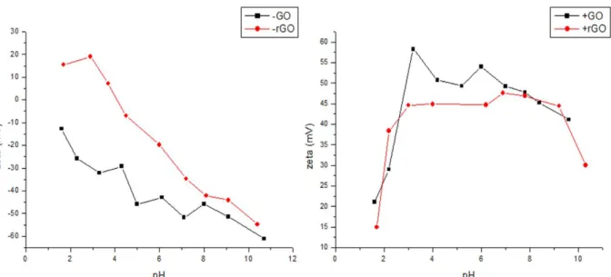
Introduction
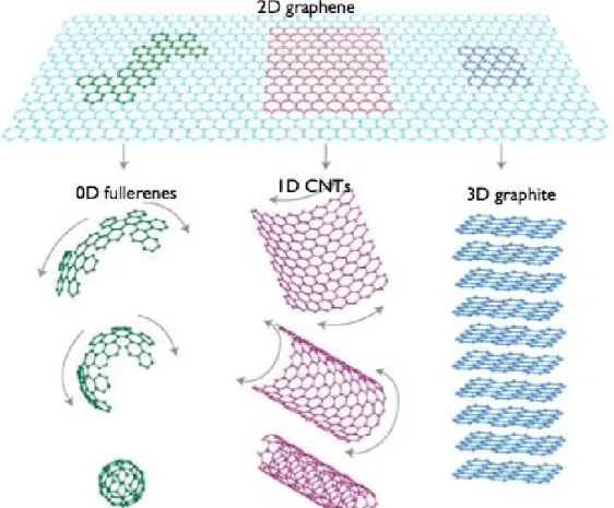
- Carbon allotropes
- What is graphene?
- Electronic properties of graphene
- Optical properties of graphene
- Thermal properties of graphene
- Mechanical properties of graphene
- Preparation of graphene
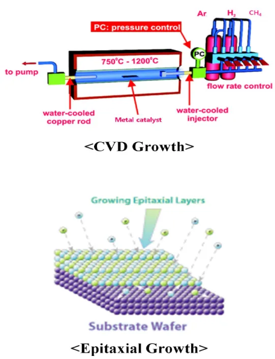
- Bottom-up method: chemical vapor deposition (CVD) & epitaxial growth (EG)
- Top-down method: micromechanical exfoliation & chemically converted graphene
- Fabrication of graphene thin film
- Applications of graphene thin films
- Transparent conducting electrode
- Catalytic counter electrode in DSSC
Quantization of the spin momentum, k⊥, leads to the formation of a set of discrete energy sub-bands for each nanotube (parallel red lines). The growth of graphene by subtractive epitaxy on semi-insulating SiC substrates offers the advantage of structural coherence over large areas, because the azimuthal orientation of the graphene is governed, to a large extent, by the crystal structure of the substrate surface. The level of oxidation may vary based on the method, reaction conditions, and precursor graphite used.
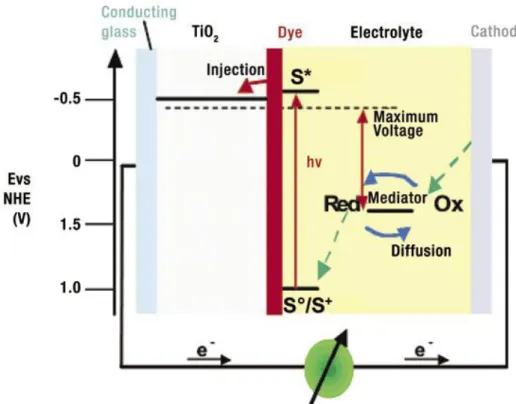
The excitation of the dye upon irradiation is followed by the injection of the generated electrons into the conduction band (CB) of the semiconductor, from where they reach the cell anode (usually conductive glass or plastic). The generated voltage is equal to the difference between the Fermi level of an electron in solid TiO2 and the redox potential of the electrolyte. A monolayer is adsorbed over the deposited TiO2 film; it is the device that absorbs sunlight at the beginning of the cycle described earlier.
Experimental
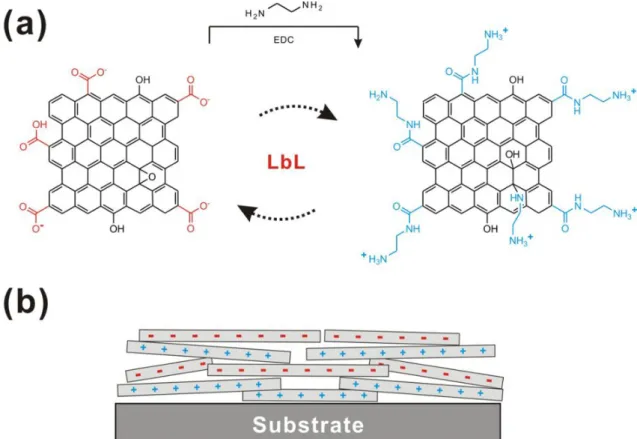
- Preparation of oppositely charged rGO
- Preparation of negatively charged GO
- Preparation of positively charged GO
- Reduction of negatively & positively charged GO
- Fabrication of rGO (or GO) multilayer films using LbL assembly
- Characterization methods of rGO multilayer films
- Fabrication of OLED device
- Preparation of GO/Pt and GO/Au hybrid films on FTO for the counter electrodes
- Fabrication of DSSC
- Characterization of DSSC
The reduction of positively charged GO suspension was carried out identically without mixing the ammonia solution. Positively charged rGO (or GO) solution (0.5 mg/ml) at pH 10 was dropped onto the silicon or quartz substrate loaded in a spin coater (ACE-200, Dong Ah Tech), which was a waiting period has been maintained. , and spun at 3,000 rpm for 30 seconds. As a rinse step, DI water at the same pH was dropped onto the substrate coated with positively charged rGO, maintained for 2 minutes and spun at 3,000 rpm for 30 seconds.
Then, negatively charged rGO (or GO) solution (0.5 mg/ml) at pH 10 was spin-coated with the same procedures, followed by the rinsing step. The transmittance of the graphene films was characterized using UV/VIS spectroscopy (VARIAN, Cary 5000). The resistance of the graphene films was measured by using the four-point probe method (AIT, CMT-SR1000N).
Positively charged GO solution (0.5 mg/ml) at pH 4 was dropped onto the FTO substrate, which was loaded into a spin coater (ACE-200, Dong Ah Tech), for 2 minutes as a waiting period in held and turned at 3,000. rpm for 30 seconds. As a rinsing step, DI water at the same pH was dropped onto the substrate coated with positively charged GO, maintained for 2 minutes and spun at 3,000 rpm for 30 seconds. Next, negatively charged GO solution (0.5 mg/ml) at pH 10 was spin-coated using the same procedures, and this was followed by a rinsing step.
Electrolyte was added to the system and a final seal completed the manufacture of the cell. The composition of the electrolyte was 0.6 M 1-hexyl-2,3-dimethyl-imidazolium iodide, 0.1 M lithium iodide, 0.05 M iodine, and 0.5 M 4-tert-butylpyridine in acetonitrile. The surface morphologies of the GO and GO/metal hybrid films were investigated by scanning electron microscopy (FEI, Nova Nanosem 230).
The transmittance of GO and GO/metal hybrid films was characterized by UV/VIS spectroscopy (VARIAN, Cary 5000).
Results
Colloidal stability of oppositely charged GO
Characterization of rGO multilayer films
- Transmittance of rGO multilayer films
- Surface morphology of rGO multilayer films
- Sheet resistance of rGO multilayer films
- Thickness of rGO multilayer films
- Comparision of rGO and GO multilayer films
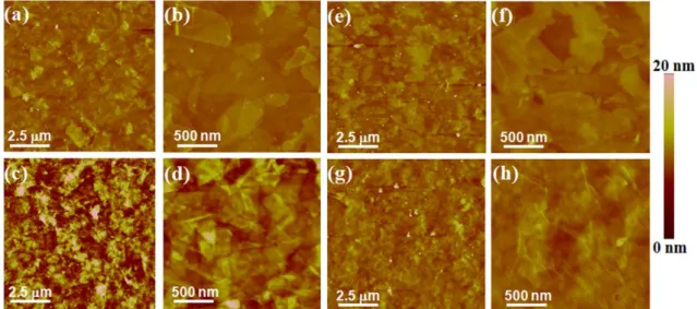
The surface morphology of the rGO multilayers was observed by atomic force microscopy (AFM) before and after annealing. The changes in surface morphology and rms roughness may be due to reorientation of the rGO sheets and densification of the thin film during annealing. The above results on surface morphology and roughness changes in rGO multilayers after annealing were similarly observed in GO multilayers.
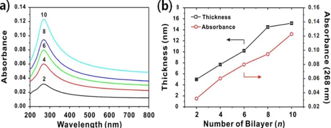
The excessively high resistance of the sheet in double layer 2 is said to be the result of an incomplete connection of the rGO plates. SEM images of rGO multilayers with 2 bilayers (a), 6 bilayers (b) and 10 bilayers (c) on Si substrates after annealing. In the fitted curves of the rGO LbL films in Fig. 17(a) , the slopes are 1.36 and 0.91 nm/bilayer before and after annealing, respectively.
The decrease in the thickness per bilayer after annealing is due to the removal of functional groups that remain even in rGO sheets. The above results indicate that the thickness of the multilayer is linearly proportional to the number of layers by LbL assembly and the thickness of one layer in rGO multilayers after annealing is 0.46 nm. Thus, we can conclude that the thickness of the multilayer thin film of rGO can be precisely controlled in the subnanometer scale by ~0.46 nm by simply changing the number of stacking layers.
According to the slopes of the fitted curves in Fig. 17(b) , the thickness is 1.54 and 2.22 nm/bilayer before and after annealing. The top image shows a photograph of a and 15 bilayer (BL) rGO multilayers deposited on a silica substrate after annealing. Thickness of LbL rGO (a) and GO (b) multilayer thin films before and after annealing. The structures between rGO and GO sheets are expected to result in different properties.
Another difference between rGO and GO sheets is the degree of reduction in transmission after annealing with increasing the number of bilayers.
Application of rGO multilayer films for OLED as a electrode
Actually, values of sheet resistance at the same transmission differ between rGO and GO sheets. The rGO multilayer showed only a 1-2% reduction in transmission after annealing, while the GO multilayer showed a 9% reduction in transmission after annealing at 10 bilayers. See Table 2) Comparing Raman spectra before and after annealing, both multilayers showed a similar trend that the ratio of ID/IG decreased from 2.60 to 2.15 for rGO multilayers and from 2.57 to 2.30 for GO multilayers.
GO/Pt and GO/Au hybrid films for DSSCs as a counter electrode
- Thickness dependence of GO multilayer films
- The role of GO multilayer films
- The role of metal nanoparticles as a reduction mediator
- Photovoltaic performance of DSSC with GO/Pt and GO/Au
- GO hybrid films with other metals for the low-cost fabrication of DSSC
Structuring DSSCs with GO/metal hybrid film on FTO as counter electrode. a) Schematic representation of the structure of the DSSC and an enlarged view of the counter electrode with metal nanoparticles on graphene oxide (GO) 2 bilayers. The binding of the metal nanoparticles is likely facilitated by the GO functional groups. Figures 22(c) and (d) show the peaks of C1s binding energy in GO/Pt and GO/Au hybrid films, respectively.
These increased efficiency levels are mainly due to the increased current density, as shown in Figure 25(a) , despite the voltage drop when GO/Pt and GO/Au are used. The reduction point is directly related to the reduction of the electrolyte at the counter electrode. As shown in the CVs (Figure 26(a)), the absolute values of current flow in GO/Pt and GO/Au films are about 13 ~ 15 % higher compared to that of Pt.
Moreover, the efficiency of the DSSC with the GO/Au counter electrode in Table 4 remained at this level for 1 month without a significant decrease (Figure 27). The same phenomena were demonstrated in CVS scans of a symmetrical sandwich cell examining the performance and stability of the counter electrode (Figure 30). It was also confirmed from SEM images that Au in the GO/Au hybrid film did not corrode after the operation of the DSSC (Figure 31).
The stability of the GO/Au films in DSSCs is consistent with the results of Kou et al. Based on the excellent device characteristics and stability of the reference GO/Pt and GO/Au hybrid films in DSSC, the performance of still cheaper base metals such as Cu, Ni and Ag for cheap counter electrodes have been investigated. The cell efficiency after 30 days was not measured due to electrolyte leakage in the cell.
Properties of the different types of GO/metal hybrid counter electrodes are summarized in Table 5 (the J-V curves are shown in Figure 32). The change of cell efficiency in DSSC with the GO/Au hybrid film as a counter electrode. SEM images of the GO/Au hybrid film before (a) and after (b) the operation of DSSC.

Conclusion
43] He, Heyong, Riedl, Thomas, Lerf, Anton & Klinowski, Jacek 1996, 'Solid-State NMR Studies of the Structure of Graphite Oxide', The Journal of Physical Chemistry, vol. 44] He, Heyong, Klinowski, Jacek, Forster, Michael & Lerf, Anton 1998, 'Nov strukturni model za grafitni oksid', Chemical Physics Letters, vol. 45] Lerf, Anton, He, Heyong, Forster, Michael & Klinowski, Jacek 1998, 'Revisited Structure of Graphite Oxide Revisited', The Journal of Physical Chemistry B, vol.
47] Buchsteiner, Alexandra, Lerf, Anton & Pieper, Jörg 2006, 'Water dynamics in graphite oxide probed with neutron scattering', The Journal of Physical Chemistry B, vol. 2006, 'Stable aqueous dispersions of graphitic nanoplatelets via reduction of exfoliated graphite oxide in the presence of poly(sodium 4-styrenesulfonate)', Journal of Materials Chemistry, vol. 2007, 'Simple approach for high-contrast optical imaging and characterization of graphene-based sheets', Nano Letters, vol.
54] Xu, Yuxi, Bai, Hua, Lu, Gewu, Li, Chun & Shi, Gaoquan 2008, 'Flexible graphene sheets via filtration of water-soluble noncovalent graphene sheets', Journal of the American Chemical Society, vol. 2009, 'Colloidal suspensions of highly reduced graphene oxide in a wide variety of organic solvents', Nano Letters, vol. 69] Cote, Laura J., Kim, Franklin & Huang, Jiaxing 2008, 'Langmuir−Blodgett Assembly of Graphite Oxide Single Layers', Journal of the American Chemical Society, vol.
Khaja, Bessho, Takeru, Cesar, Ilkay, Liska, Paul, Humphry-Baker, Robin, Comte, Pascal, Pechy, Peter & Gratzel, Michael 2006, 'Highly efficient dye-sensitive solar cells based on carbon black counter electrodes', Journal of. 2010, 'Pt-free transparent counter electrodes for dye-sensitized solar cells prepared from carbon nanotube microspheres', Journal of Materials Chemistry, vol. 95] Xu, Chao, Wang, Xin & Zhu, Junwu 2008, 'Graphene-Metal Particle Nanocomposites', The Journal of Physical Chemistry C, vol.
97] Chen, Xiaomei, Wu, Genghuang, Chen, Jinmei, Chen, Xi, Xie, Zhaoxiong & Wang, Xiaoru 2011, 'Synthesis of "pure" and well-dispersed Pd nanoparticles with excellent electrocatalytic properties on graphene oxide', Journal of American Chemistry society, p.