Naehyuck Chang Dept. of EECS/CSE
Seoul National University [email protected]
E L P L E mbedded L ow- P ower L aboratory
Embedded System Application
4190.303C
2010 Spring Semester
CRT, LCD, OLED and display systems
Display Devices
Bulbs
Nixie tube (Numeric Indicator
eXperimental-1) - The first electronic digital readout
Vacuum fluorescent display Light emitting diode
LCD
OLED
Display System Architecture
Principle of operation
Single display
Group display
Massive display
More efficient method is required
Dynamic Display
Spinning dishes
Static spinning
Spin one dish per hand
Dynamic spinning
Spine several dishes per hand Use of inertia
Static display
Display the device the same information at all times
Dynamic display
Use of human perception Pulse display for illusion
For group and massive display
Dynamic Display
Human eyes cannot perceive a light source that is blinking faster than 30Hz
CRT Display
Cathode Ray Tube (CRT)
CRT Display
Horizontal and vertical deflection
Horizontal deflection control
Vertical deflection control Intensity
BW or color
CRT Display
Raster scan
Left to right Top to bottom
Rely on afterimage
30Hz or higher refresh rates
Video timing
Hsync signal for horizontal retrace Vsync signal for vertical retrace
CRT Display
Sweep signal
Saw tooth waveform
15.75KHz saw tooth for the horizontal scan 30Hz saw tooth for the vertical scan
CRT Display
Video signals
RGB – to electric gun
Hsync – for horizontal scan Vsync – for vertical scan
RGB can be digital or analog Composite signal
Sync signals synchronize the saw tooth
waveforms
Liquid Crystal Display
LCD stands for Liquid Crystal Display
Advanced display system
“Liquid Crystals” are semi-solid substances that are sensitive to temperature and electricity
Commonly used in
Digital watches, calculators, laptops
Compared with conventional CRT display systems
Advantages
Light Thin
Low power consumption
Disadvantages
Expensive for computer display
Display size is limited by manufacturing complexities Slow response
Non linear color
Liquid Crystal Display
Transmissive mode
Illuminated from behind using a backlight lamp Powerful backlight source due to the low
transmittance (less than 10%)
High image contrast (typically 300:1)
Reflective mode
Illuminated from the front using an ambient light or a frontlight lamp
Very low power consumption with the frontlight turned off
Low image contrast (typically 10:1) due to the low reflectance (3 to 5%)
Transflective mode
Partially transmissive and reflective
Transflective mode Reflective mode Transmissive mode
Passive Matrix LCD
Advantages
Very simple design Inexpensive
Reduced number of electrodes
rows + columns electrodes for rows X columns pixels
Disadvantages
It has a slow response time
This implies slow image refreshment rate and hence lower quality of changing display
It has inherent imprecise voltage control
That causes pixels around the required pixel to be partially activated and thus affecting the quality
Active Matrix LCD
TFT LCD panel
TFT-array substrates (CST: a storage capacitor and
CLC: an equivalent capacitor for a liquid crystal cell) Structure of a transmissive LCD panel
Active Matrix LCD
LCD driver circuit
LDIs
LCD driver integrated circuits
Alternate voltage generation to prevent any deterioration of image quality resulting from the DC stress of liquid crystals
Modulation of the voltage to control the transmittance of liquid crystals
Analog LDIs
Capable of producing a continuous voltage signal
Digital LDIs
Capable of producing discrete voltage amplitudes
n-bit LDI → 2n transmittance levels for each sub pixel → 23n colors
LCD Backlight Systems
EL (Electroluminescence)
Colored backlight
Not applicable to color LCDs
Thin and planar
No need of a diffuser
High AC voltage is required for EL driving
LCD Backlight Systems
Colored LED
Low cost
Colored backlight
Not applicable to color LCDs
Easy low-voltage DC driving Need of a diffuser
LCD Backlight Systems
Backlight system
Principle of operation for CCFT
Electrically excited mercury → Ultraviolet light radiation → Phosphor coating reaction → Visible light
High-voltage inverter
Kick-off voltage: 1000+V AC Nominal voltage: 400 to 450 V AC
Structure of a cold cathode fluorescent tube
LCD Backlight Systems
White LED backlight
High luminance Low power Longer life
LCD Backlight Systems
White LED backlight
High luminance Low power Longer life
Sidelight-type backlight unit
Organic Light Emitting Diode
OLED stands for Organic Light Emitting Diode
An OLED is an electronic device made by placing a series of organic thin films between two conductors. When electrical current is applied, a bright light is emitted
A device that is 100 to 500 nanometers thick or about 200 times smaller than a human hair
Types of OLEDs
Passive-matrix OLED Active-matrix OLED Transparent OLED Top-emitting OLED Flexible OLED White OLED
Organic Light Emitting Diode
Compared with LED and LCD
Advantages
Thinner, lighter and more flexible Plastic substrates rather then glass
High resolution (< 5 µm pixel size) and fast switching (1-10um) Do not require backlight, light generated
Low voltage, low power and emissive source Robust Design (Plastic Substrate)
Larger sized displays
Brighter - good daylight visibility Larger viewing angles -170º
Disadvantages
Lifetime
White, Red, Green: 46,000-230,000 hours → about 5-25 years Blue: 14,000 hour → about 1.6 years
Expensive
Susceptible to water
Overcome multi-billion dollar LCD market
Organic Light Emitting Diode
How OLED works
Voltage applied across Cathode and Anode
Typically 2V-10V
Current flows from cathode to anode
Electrons flow to emissive layer
Electrons removed from conductive layer leaving holes
Holes jump into emissive layer
Electron and hole combine and light emitted
Organic Light Emitting Diode
How OLED works
Different Colors
Type of organic molecule in the emissive layer 3 molecules used -RGB
Intensity/brightness
Amount of current
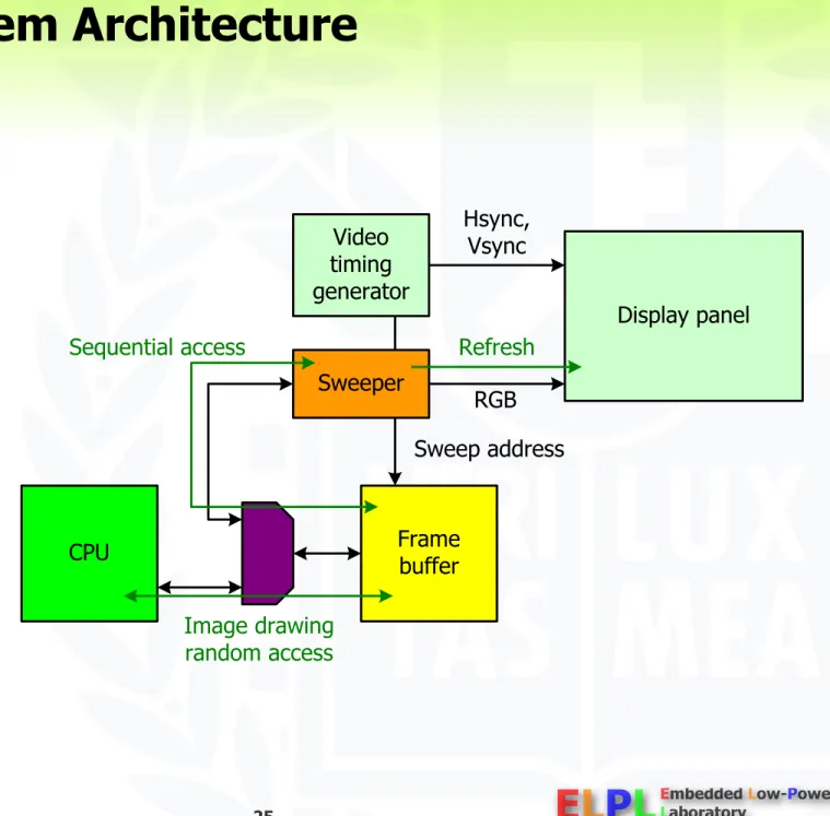
Display System Architecture
Character display
Frame buffer Font ROM Sweeper
Graphic display
Frame buffer Sweeper
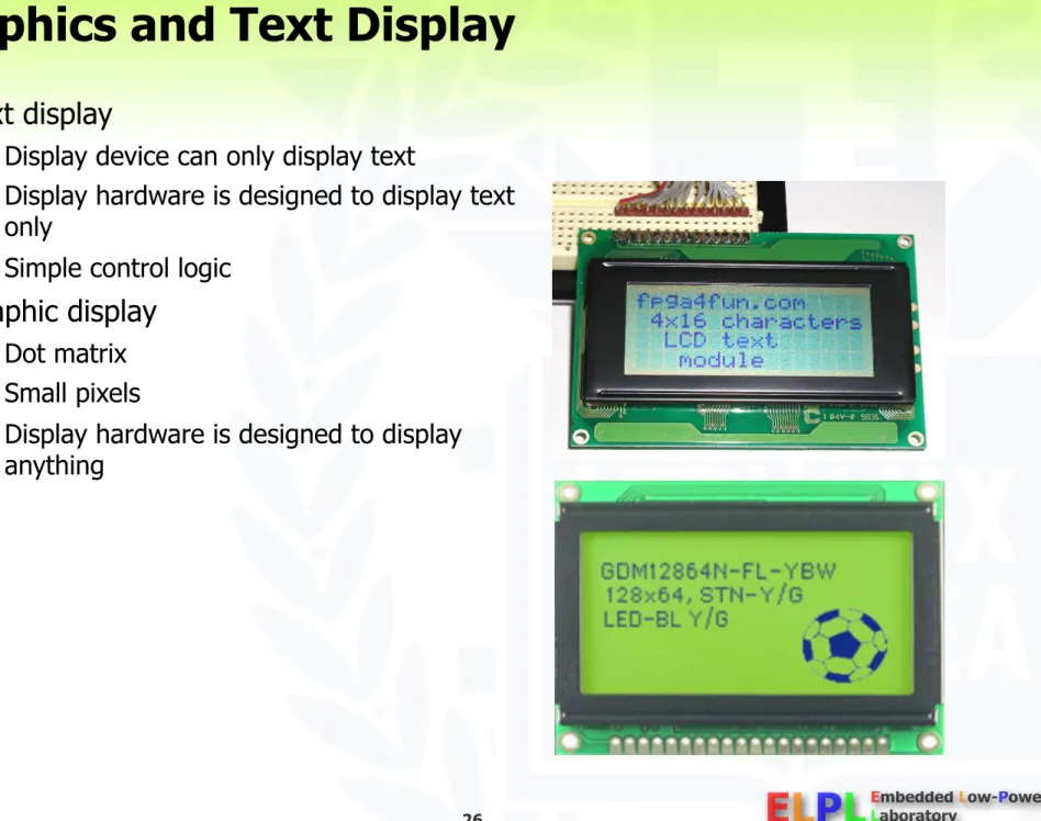
Graphics and Text Display
Text display
Display device can only display text
Display hardware is designed to display text only
Simple control logic
Graphic display
Dot matrix Small pixels
Display hardware is designed to display anything
Character Display
Character only display
Frame buffer contains only column * row
* ASCII + attribute (8 or 16 bit) Attributes
Bold, underline, blinking, etc.
Font ROM contains bit-map fonts Scroll
Rewrite the frame buffer Move a pointer
Smooth scroll increments the vertical counter
Poor CPU and frame buffer performance may result in wave scroll or whites on the screen
Graphics characters
Graphics Display
Frame buffer contains bit map data: pixel Attributes are emulated by changing the frame buffer contents
E.g. blinking → repeat write and erase a character
General architecture
Requires higher performance
Graphics Display Definitions
Pixel
Picture element, the basic building block on a computer display/image i.e. computer image consists of many pixels
Bits Per Pixel (bpp)
The number of bits assigned per pixel to describe the brightness and color information of that pixel.
Also called: Bit depth (more the number of bpp, better the quality of image)
Monochrome panels
Only one color is possible
If 1 bpp, black-and-white mode, or in 2 bpp and 4 bpp for shades of gray
Color panels
4 bpp and higher (4, 8,12,16,24 bpp etc)
Different bits used to hold RGB info, the primary colors
Ex: Usual spec for white in 24 bit is 255, 255 ,255 means Red value = 255, Green value = 255 and Blue value = 255 (8 bits each)
Graphics Display Definitions
Resolution
It is the number of pixels that the display panel contains
CRT display resolution is limited by the horizontal and vertical clock frequencies LCD display resolution is determined by the number of pixels on the panel
It is expressed as the number of pixels on the horizontal axis (columns) and the number of pixels on the vertical axis (rows). Total number of pixels is calculated by multiplying the two quantities.
E.g.: 320 X 240 TFT panel
320 Columns and 240 rows
Total Memory required: 320 X 240 X bpp bits
More resolution means better the image quality and sharpness
Graphics Display Definitions
Frame rate
Refresh rate
NTSC – 30 frame/sec
Human eye can recognize flickering around 30Hz frame rate
Computer monitors – over 60Hz
60Hz frame rate is basically flicker free
Near 60Hz refresh, however, may interfere with light bulbs 72Hz or higher frame rate is used for quality display
LCD Systems
Raster-scan displays
Raster: a set of horizontal scan lines
Image: formed from the raster (matrix of pixels
pixmap)LCD controller
Sweep operation to control the color intensity of each subpixel periodically
Raster-scan operation
LCD Systems
LCD system architectures
Simple architecture
Shared main and frame buffer memory as a cost-effective solutionSlowed-down CPU performance
Software graphics package for scan conversion Slow scan conversion procedure
High-end architecture
Discrete frame buffer memory for high bandwidth and large capacity No tied-up CPU execution
Hardware graphics processor in the LCD controller for scan conversion Fast scan
conversion procedure (optional) A discrete memory device for the frame buffer A dedicated portion of the system memory
for the frame buffer
Common LCD system architectures
Graphics Programming
Text display
Bit map font
Calculation of the character location Block move font data to the frame buffer
Line drawing
Dot fill
Line drawing algorithms
Graphics library
2D graphics
2D objects: line, circle, UI objects, etc.
3D graphics
Graphics pipeline
Object data geometry calculation lighting rasterization hidden surface elimination
LCD Interface
Embedded frame buffer type
Same to memory interface (SRAM) Address, data and RD/WR control Additional control inputs
Intensity Backlight Display on/off
VGA compatible interface
Same to CRT interface RGB, Hsync and Vsync
TTL, LVDS or serial interface Additional control inputs
Backlight Display on/off
Timing diagram
Panel Interface Signals
Horizontal timing (timing per one line)
H_WIDTH: defines the width of the HSYNC pulse (at least 1)
H_WAIT_2: defines the delay from the end of HSYNC to the beginning of OE
H_WAIT_1: defines the delay from the end of OE to the beginning of the HSYNC pulse XMAX: defines the total number of pixels per line
HSYNC width, H_WAIT_2,H_WAIT_1, are all programmable
Panel Interface Signals
Vertical timing (timing per one frame)
V_WAIT_1 is a delay measured in lines. If V_WAIT =1, there is a delay of one HSYNC before VSYNC
For V_WIDTH(vertical sync pulse width) =0, VSYNC encloses one HSYNC pulse. For V_WIDTH = 2, VSYNC encloses two HSYNC pulses
V_WAIT_2 is a delay measured in lines. For V_WAIT_2 = 1 , there is a delay of one HSYNC after VSYNC.
The delay from end of one frame to the beginning of the next is programmable
Panel Interface Signals
DLS: Motivation
High power consumption of liquid crystal displays
High-resolution, high-color TFT LCDs as the de-facto display standard of portable electronics
Small size, light weight, and low power consumption comparing with a CRT (cathode-ray tube) Powerful backlight source and large-capacity frame buffer memory
Still high power consumption of the display in portable devices
Immature energy-aware display technology
Previous research focused on the device level approach
Much higher energy efficiency of current LCD panels and backlight tubes than before.
No consistent system-level low-power design techniques for LCD systems
c.f. DVS (Dynamic Voltage Scaling) for processors c.f. DPM (Dynamic Power Management) for peripherals c.f. Memory energy optimization
c.f. Bus encoding for interconnections
DLS: Problem Statement
Energy reduction of the display system at the system level
Power reduction of two major display components
Backlight system Frame buffer system
Lossy approaches, but no appreciable display quality degradation
Cell phone
Portable media player
Personal digital assistant
DLS: Research Contributions
Energy characterization and analysis of LCD systems
Energy characterization of color TFT LCD components by accurate energy measurement
System-level energy analysis of LCD systems in portable electronics
System-level low-power display techniques
Dynamic luminance scaling
Energy- efficient backlight systemPapers: IEEE Design & Test of
Computers 2004, IEEE Transactions on VLSI Systems 2004, ESTIMedia 2004 and ISLPED 2002
Frame buffer compression
Low- power frame buffer systemPapers: ASP-DAC 2004 and ESTIMedia
System-level power analysis for running a movie player on the reference platform (W)
Target components for frame buffer compression
Target component for dynamic luminance scaling
DLS: Research Contributions
Working prototype implementation supporting the proposed low-power techniques
Validation of the proposed techniques by the measurement of the actual display power consumption
Awards: Low-Power Design Contest Award at ISLPED 2002, 2003 and 2004
Demonstration of the energy reduction in view of the total power consumption of a reference platform
Integrated framework to evaluate the power reduction achieved by the
proposed techniques on a reference platform
DLS: Power Consumption Models
Reference platform with a high- quality liquid crystal display
Energy models associated with dominant power consumers
Display components in a dash-lined box
Total system energy consumption including the computing part
Emphasizing the energy reduction in view of the whole system
Energy models for a portable embedded system
DLS: Power Consumption Models
LCD panel
Components
Color TFT LCD panel
High-color 640x480 LP064V1 from LG-Philips
LCD panel interface
4 inch long 4bit control bus and 16bit data bus
@25MHz
Energy model
Similar to the energy state machine of memory buses
Panel transmittance
Amount of charge that must be stored in the TFTs
Panel power consumption Panel power consumption
proportional to the number of blocked colors
Energy state machine for the LCD panel interface
Similar to the energy state machine of memory buses
High power consumption due to the large capacitance of a flat cable comparing with that of memory buses
Power consumption of the LCD panel
DLS: Power Consumption Models
LCD controller
Components
Xilinx Spartan-II FPGA
XC2S-150FG456 LCD controller
3 GCLKs, 2 GCLKIOBs, 2 DLLs, 182 IOBs, 926 SLICEs
64,656 equivalent gate count
Energy model
229.0mW @66MHz reported by Xilinx XPower
Power estimation software from Xilinx 2.5V VCCint , 3.3V VCCout
DLS: Power Consumption Models
Backlight
Components
CCFL (Cold Cathode Fluorescent Lamp)
High-voltage inverter (12V DC 300V to 550V AC)
Superior optical efficiency: 60 to 100 lumens/watt
White LED
Optical efficiency: 20 lumens/watt
Energy model
Average power consumption
proportional to the backlight luminance
Digital multimeter Power
Illuminometer (Minolta LS100) Luminance
Characterizing the power-luminance relation of the backlight
Steady-state luminance and power consumption
Reference power
Reference luminance
DLS: Reference Platform
Significant display power
Document viewer (interactive)
CPU Sleeping
Memory Power-down state
Spread sheet (memory intensive) Movie player (computing intensive)
Still minor computing power
Document viewer
Movie player Spread sheet
DLS: Related Work
Device power analysis
LCD panel
TFT power modeled by a quadratic function of the pixel value
CCFL backlight
Piece-wise linear function of the luminance
Considering the saturation effect of the optical efficiency
System level power analysis
Energy characterization of GUI platforms
Hardware, software, and application perspectives
Insights for improving the energy efficiency of GUI platforms
Additive color reproduction system
Qualitative match of a color (C) Backlight luminance (L(v))
Luminance of a pixel (Y(C,v))
DLS: Image Reproduction
R, G and B: primary color values Aj: matching values for color C
Wj: matching values for a backlight (typically white) v: control input voltage of an high-voltage inverter : wavelength of a backlight
Pj(v, ): spectral energy distribution of the primary colors V( ): relative luminous efficiency
: product of the aperture ratio (around 2/3) and the transmittance of the two polarizers (around 1/3) Structure of a transmissive LCD panel
DLS: Image Compensation Algorithms
Principle of DLS (Dynamic Luminance Scaling)
Backlight dimming for power saving
L(v) L(v’) such that L(v’) < L(v)
Restoring brightness/contrast by appropriate image compensations
C C’ to maintain the same intensity perceived by human eyes
Original Backlight dimming with appropriate
image compensation
DLS: Image Compensation Algorithms
Brightness compensation
i-th image (Ci)
Backlight dimming
Brightness compensation
0 Normalized color 1
0 Normalized color 1
(b) Original color spectrum
(d) Luminance enhanced spectrum Red Green Blue Number of pixels
Number of pixels 0 10000 20000 30000 40000 50000
0 10000 20000 30000 40000 50000 (a) Original image
(c) Luminance enhanced image
Example of brightness compensation H: horizontal resolution
DLS: Image Compensation Algorithms
Distortion ratio (Di)
RGB color space
YUV color space HSV color space
Color transformation function (Tbc(c))
0 Normalized color 1
0 Normalized color 1
(b) Original color spectrum
(d) Luminance enhanced spectrum Red Green Blue Number of pixels
Number of pixels 0 10000 20000 30000 40000 50000
0 10000 20000 30000 40000 50000 (a) Original image
(c) Luminance enhanced image
H(Mi): histogram function Example of brightness compensation
DLS: Image Compensation Algorithms
Histogram stretching (image enhancement #1)
Extension of brightness compensation
Histogram stretching with respect to the low threshold TL as well as the high threshold TH
Contrast stretching
Color transformation function (Ths(c))
Distortion ratio (Di)
Example of image enhancement
GUI components
Brightest area dominates the image
Histograms skewed to bright areas
DLS: Image Compensation Algorithms
Histogram equalization (image enhancement #2)
Maximum readability
Wider-spanning color histogram of the image Better readability than histogram stretching
Applicable to objects, whose colors are not important (such as text-based screens)
Color change of most pixels Worse color tonality than histogram stretching
Not applicable to streaming images due to the inter-frame color inconsistency
Color transformation function (The(c))
DLS: Image Compensation Algorithms
Context processing
Preventing small foreground objects from having similar colors to their background
No correlation between the number of pixels and their importance (e.g. text)
Color merge of some minor colors into their background colors after histogram equalization No longer distinguishable
Re-stretching of foreground and background colors to maximize the color difference with context information of applications
Color transformation function (Tcp(c))
b(c): background color of an object whose color is c
DLS: Image Compensation Algorithms
Computational complexity
Construction of the transformation function
Histogram construction
Determining threshold TH and TL
Transformation of the pixel color value
Approach #1: addition, subtraction, multiplication, division and comparison for each pixel Approach #2: table lookup (desirable for a high-resolution screen)
DLS: Implementation Layers
Design considerations
Energy consumption
Energy reduction from backlight dimming
Energy overhead incurred by the image compensation process
Performance penalty Application transparency
Hardware-software partitioning
Four different implementation layers
Application program Windows system
Frame buffer device driver LCD controller hardware
DLS: Implementation Layers
Application program
Pros.
Application-specific optimization using the application context
e.g. approximate histogram in a compressed (10x) domain for an MPEG decoder Reduced histogram construction overhead
Cons.
Full-screen application only
Backlight as a shared resource
Heavy porting burden
No standard interface between the application and the DLS function Application’s proprietary structure ad-hoc approach
Conventional
Application embedded or windows system embedded
Paper
- IEEE Transactions on VLSI Systems 2004 - ISLPED 2002
Demonstration
- SIGDA University Booth of DAC 2002
- Low-Power Design Contest of ISLPED 2002
DLS: Implementation Layers
Windows system
Pros.
Energy benefit of applications without their core modifications Systematic porting procedure
Cons.
Source code modification of the windows system and applications Performance degradation
comparing with the application- embedded approach
Conventional
Application embedded or windows system embedded
Paper
- IEEE Transactions on VLSI Systems 2004 Demonstration
- SIGDA University Booth of DAC 2003
DLS: Implementation Layers
Frame buffer device driver
Pros.
Application transparency
No need to modify applications or windows system
Cons.
Very high energy overhead for histogram construction due to synchronization (typically @60Hz) Improper synchronization between the application and the DLS
functional blocks in the driver Visual artifacts
No context information
Rebuilding of the transformation function caused by only a slight change of the frame buffer
Conventional
Application-transparent device driver
DLS: Implementation Layers
LCD controller hardware
Pros.
Application transparency
No need to modify applications or windows system
No synchronization problem
No additional frame buffer accesses for histogram construction or color transformation
Performed on-the-fly during a sweep operation (typically @60Hz)
Cons.
Additional silicon area and energy overhead incurred by 2n comparators and counters for histogram
construction Not a feasible implementation as it is
Conventional
Application-transparent hardware
Paper
- IEEE Design and Test of Computers 2004 Demonstration
- Low-Power Design Contest of ISLPED 2004
DLS: Backlight Management Framework
Input:
Simple slider knob for user preferences
Backlight luminance Image quality
Power budget
Paper
- IEEE Design and Test of Computers 2004
The EDLS framework
Output:
Harmonious combination of brightness compensation and image
enhancement across panel modes for transflective LCDs
DLS: Implementation
Prototype specification
LG-Philips LP064V1 6.4” transmissive color TFT LCD panel with a CCFL backlight
Xilinx XC2S-150FG456 Spartan-II FPGA LCD controller
Samsung K4S641632D SDRAM frame buffer memory
PLX PCI9054 PCI bridge
Frame buffer device driver for the Linux kernel 2.4.19
DLS: Implementation
Implementation of a backlight luminance controller
CCFL’s slow response
Closed-loop control with a feedback input
PID(proportional integral differential) control by sensing the luminance with a photo diode LED’s fast response
Open-loop controlv (control input voltage): 2.3V to 0V VD (Photo diode output)
Backlight luminance control circuit:
(a) built-in common circuits for backlight dimming, (b) a built-in circuit for a CCFL backlight system,
(c) a built-in circuit for a white LED backlight system, and (d) an add-on circuit to enhance the response time of the CCFL backlight
Step response of the CCFL backlight luminance
DLS: Implementation
Expected energy gain by DLS
Actual energy gain by DLS with the PID control
Energy overhead by the PID control
Enhanced (2000x) full-scale step response with the PID control
ui: backlight control command for the target luminance Vi: backlight control input voltage with the PID control VDi: photo diode output voltage for the feedback input
DLS: Implementation
Implementation of image compensation algorithms
MPEG-4 decoder (application)
New procedures after the IDCT in a YUV color space
Brightness compensation
Java 2 Micro Edition Personal Basis Profile (middleware)
Additional methods and components in the lightweight Java AWT (Abstract Window Toolkit) (e.g. java.awt.BrightnessController)
Brightness compensation
Image enhancement: histogram stretching and histogram equalization Context processing
LCD controller (hardware)
On-the-fly image processing hardware in the LCD controller
Brightness compensation
Image enhancement: histogram stretching
Compact histogram construction logic (e.g. 16bpp 12bpp) together with the image processing hardware
DLS: Experimental Results
MPEG-4 decoder (application)
Power saving for a cartoon stream by DLS Power saving for a movie stream by DLS
Original DLS (Di=0.03)
DLS: Experimental Results
Java 2 Micro Edition Personal Basis Profile (middleware)
DLS: Experimental Results
LCD controller (hardware)
Relatively small area and power
overhead for the image compensation logic such as multipliers and
comparators
Exponentially increasing area overhead for the histogram construction
CompactionPower and area overhead of the LCD controller implementation with an FPGA supporting the hardware DLS-d
Original DLS (d=6)
DLS-1
DLS-2
DLS-3
DLS-4 Compact
histogram construction
Comparison between the original software DLS and the application-transparent hardware DLS for a movie stream
Compact hardware DLS
Approximated version of histogram (step size over 1)
Higher T’H and lower T’L than original TH and TL
Less backlight power reduction, but higher image qualityDLS: Experimental Results
Backlight power reduction and objective image quality measures of original DLS and hardware DLS-4
DLS: Related Work
Backlight luminance scaling
Image compensation algorithms
CBCS (Concurrent Brightness Contrast Scaling) HEBS (Histogram Equalization for Backlight Scaling) DTM (Dynamic Tone Mapping)
Streaming image quality enhancement for backlight luminance scaling
QABS (Quality Adapted Backlight Scaling)
RGB LED backlight
Backlight power management
Backlight autoregulation
Camera-driven display power management
DLS: Conclusions
Color TFT liquid crystal displays for portable embedded systems
Small size and light weight
High power consumption of LCD systems
Powerful backlight source (30% of total system power)
Large-capacity frame buffer memory (17% of total system power)
Power consumption analysis
Device-level power analysis
LCD panel and its interface bus
Backlight lamp and its high-voltage inverter Frame buffer memory and its associated buses
System-level power analysis
Reference platform
High-performance CPU and memory systems
Quality LCD system (VGA resolution, high-color (18-bit))
DLS: Conclusions
Dynamic luminance scaling
Key idea
Backlight dimming for power saving
Restoring brightness/contrast by appropriate image compensations
Four kinds of image compensation algorithms
Brightness compensation
Histogram stretching (image enhancement #1) Histogram equalization (image enhancement
#2)
Context processing
Three kinds of implementation layers
MPEG-4 decoder (application) Java 2 Micro Edition (middleware) LCD controller (hardware)
Backlight power saving by up to 71%
according to the color histogram of displayed
Dynamic luminance scaling
DLS: Conclusions
Future directions
Enhancement of the image quality further for video streaming applications
Definition of an image quality metrics on the inter-frame brightness distortion considering characteristics of the human visual systems
Avoiding the abrupt and frequent backlight luminance changes by examining the color histogram of future picture frames in advance
Considering the nonlinear relations between the color value and the liquid crystal transmittance
Application-transparent software DLS implementation
Utilizing the palette memory in the LCD controller for the color transformation in the low color depth
Design of a lightweight histogram construction algorithm in a software