Introduction
Research motivation
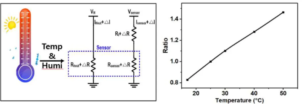
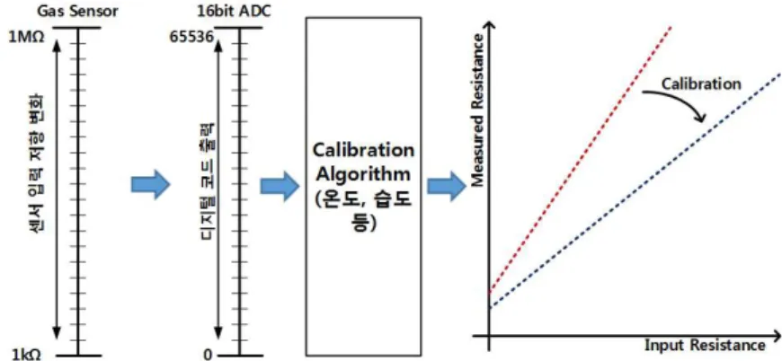
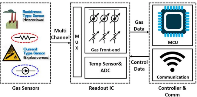
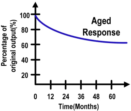
Gas sensor systems are applications that require periodic inspection and calibration as shown in Fig.2 [4]. For that reason, the gas sensor system requires inspection personnel and corresponding costs each time to calibrate. To perform self-calibration of gas sensors, a gas sensor system including a gas ROIC capable of providing various functions is required, as shown in Fig.
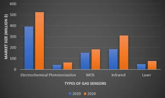
Gas sensor trend
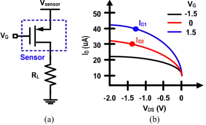
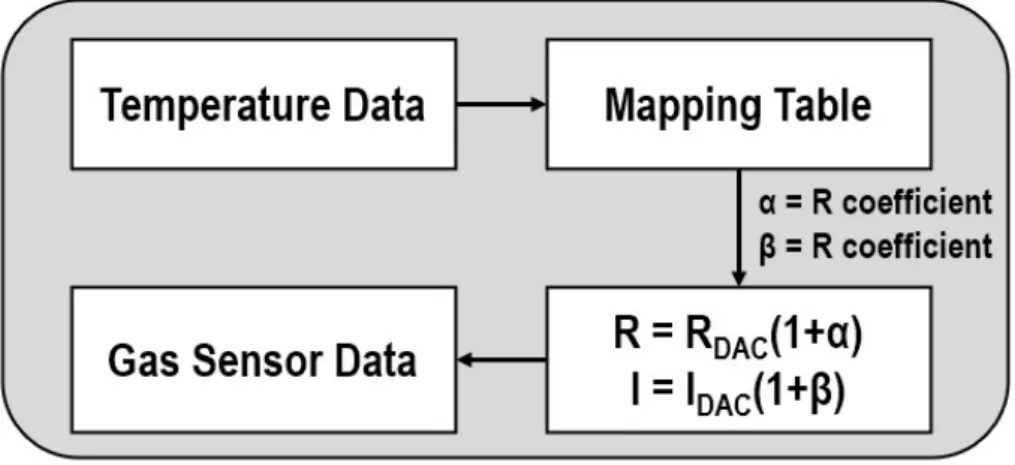
The gas sensing stage is connected to the proposed gas ROIC for resistance and current measurement. In gas sensor mode, the resistance and current of the gas sensor are measured by the RDAC, comparator and ADC. A voltage of 5 V was applied to the gas sensor module through the power supply and the operation of the sensor was confirmed.
Research Background
Gas sensor interface
- Gas sensor system
- Gas sensors
- Gas sensor structure
- ADC
- Digital processing
The gas sensor current in low current mode can be obtained using the formula below. The gas sensor current in high current mode can be obtained using the formula below. As a result, the correlation between the Ro slope of the gas sensor and the Res slope is very low.
Gas sensor & system issues
- Aging
- Environment variables
- Gas selectivity
- Gas sensing range
- Performance optimized ADC
Limitations of Previous Research
Self-calibration of gas sensor
In the absence of gas, B1 can be obtained, which corresponds to the offset of the gas response. Then the reference gas is exposed to the installed gas sensor and the resistance Y of the gas sensor is saturated, becoming B2. The newly obtained linear equation is stored in the gas sensor module and used to determine the concentration.
Pattern recognition
To enable real-time gas pattern recognition, gas data is transmitted to the server by combining the wireless communication module as shown in Fig. The server analyzes gas data with PCA and ANN and even supports gas monitoring services. However, as the number of gas data and locations to be detected increases, the gas data to be analyzed increases, which leads to a server overload.
Drift compensation
Finally, incorrect adaptation model or training may occur. Table Ⅳ shows drift compensation based on measurement data. Correlation coefficients corresponding to the low, middle and high stages are obtained by comparing the measured environmental variables and gas sensor data. These coefficients make the sensor as linear as possible and the gas sensor information does not change for the same gas concentration.
The drift compensation via ANN is a popular method in recent years, and various environmental variable data and gas data are trained via a suitable ANN structure. The weighing values obtained through training linearize the responsiveness of the gas sensor and eliminate the influence of various environmental variables.
Wide dynamic range
Fixed performance
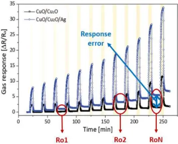
The conventional gas sensor calibration method involved exposing the gas to the sensor and calibrating it via the changing resistance and current values of the sensor. Ideally, it should perfectly return to the air condition gas sensor value, but the difference will occur as shown in figure. Due to this phenomenon, the response of the gas sensor is expressed as a value other than '1', which causes an error in the gas sensor concentration.
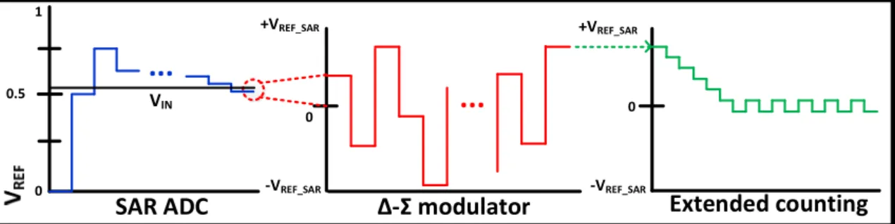
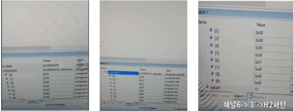
The generated code is loaded into the MCU and pattern recognition is performed in the gas sensor module. In high resistance mode, IDAC_S current can only be sent to the gas sensor to measure the gas sensor. When no gas is detected, only 8-bit SAR operation is performed to reduce the power of the gas sensor system.
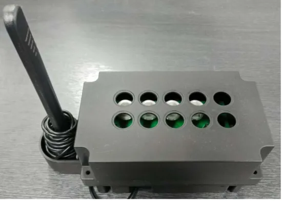
The gas sensor module is packaged as a commercial product and the gas sensor is connected to the PCB via wiring. Gas sensor data is obtained by connecting to a laptop via the module's Bluetooth connection. In addition, the selectivity of the gas sensor is ensured and the gas sensor appears to react only to the target gas.
Gas sensing characteristics of FET-type gas sensor having ink-printed WS2 sensing layer.
Proposed Gas Sensor Interface
Proposed gas sensor calibration
- Methodology of response self-calibration
- Ro update
- Methodology of self-calibration for FET type sensor
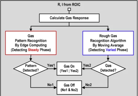
In the gas sensor system, the relationship between the gas sensor response and the concentration is embedded, and the gas concentration is derived through this. If Rs is obtained by conventional method, the gas sensor conversion proceeds only in steps 1 and 2. The proposed intelligent gas sensor system reduces server overload through a pattern recognition algorithm based on edge computation.
The gas sensor system is unreliable because the gas sensor has varying responsiveness depending on the time and frequency of use. The gas detection algorithm was designed based on gas sensor response data against gas leakage and uses a gas pattern detection algorithm and a moving average. With edge computing, gas pattern recognition is performed in the gas sensor module to reduce server overload and enable gas recognition algorithms.
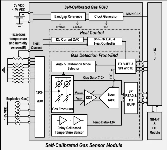
To efficiently operate the proposed indirect self-calibration gas sensor system, a gas ROIC was designed. Since the gas sensor system must continuously detect gas, it must be operated efficiently depending on the situation.
Gas ROIC interface
Gas response slope self-calibration
Heater controller
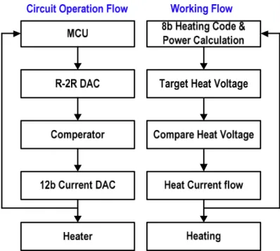
To ameliorate these problems, the scheme of the proposed heater control is shown in Fig. First, the MCU sends an 8-bit heater code to the R-2R DAC to set the desired heater voltage. The heater voltage is changed to match the reference through a series resistor and compared to the R-2R DAC output voltage through a comparator.
If the heater voltage is small, the comparator outputs "0" and this signal increases the current of the 12-bit DAC. This process continues and eventually the regulated heater voltage and the R-2R DAC output voltage become equal. Unlike other heater controllers, the proposed heater control does not require an ADC to measure the power.
Since the heating resistance of each gas sensor is different, a different gas sensor response occurs due to a different heating temperature when the same heating voltage is applied as before. However, the proposed heating control delivers the same heating output or desired one to each different heating resistance.
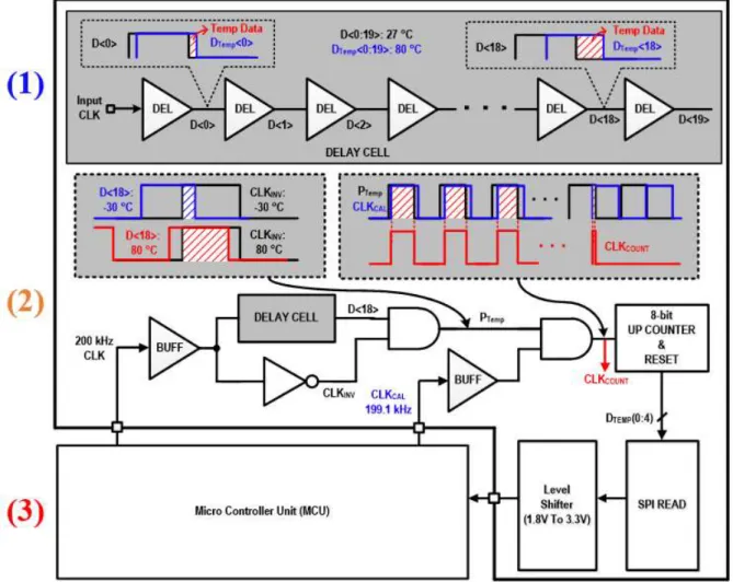
Fully digital temperature sensor
If the coarse 8-bit code result is all '0', it means that the resistance of the gas sensor is smaller than the reference resistance used in RDAC1. If the coarse 8-bit code result is all '1', it means that the resistance of the gas sensor is greater than the maximum resistance used in RDAC1. The gas ROIC sensor module consists of a gas sensor module on the top, a ROIC module in the middle and an LTE module on the bottom.
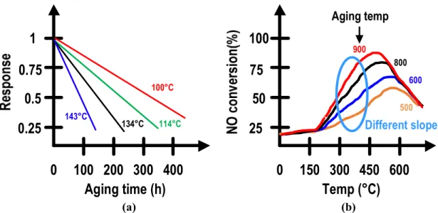
The manufactured gas sensor module is designed to measure 10 types of gas sensors at the same time. In the process of expressing the gas sensor Ro slope as an equation, S1 represents an initial value at which aging does not proceed. The proposed gas sensor system can indirectly obtain the changed gas sensor response by using the Ro slope instead of the calibration gas, which is the input required for the inspection and calibration of the gas sensor.
Since the gas sensor system does not require continuous inspection and calibration, it is possible to significantly reduce the human resources and costs of the operation. In addition, an optimized gas ROIC is designed to efficiently power this gas sensor system and have versatility. However, this method causes server overload as the number of gas sensor modules increases.
I would like to thank Hee-Young Chae, Kyunghwan Park and Su-Bin Choi for their research and help on the gas sensor system.
Chip calibration
Wide dynamic range gas detector
Dual mode IADC
Fabrication and Measurement Results
Fabrication results
- Gas ROIC sensor module
- Gas ROIC chip
- Monitoring system
The ROIC module includes KLDX-0202-A so it can be controlled via the SMPS adapter connection. Explosion-proof packaging is designed to prevent explosions when high-concentration explosive gas comes into contact with high-temperature gas sensors. The upper part of the explosion-proof package has a hole to collect gas, and an antenna for LTE communication is connected to the left side.
The sensors on the right are designed to be disposable, and if the sensor fails, only the new sensor is replaced without discarding the entire sensor board. The gas ROIC module on the right of the figure consists of a low dropout (LDO) for power supply, MCU and gas ROIC. The designed gas ROIC chip consists of ROIC with wide dynamic range, SAR ADC to support low power, IADC for high resolution sensing, heating controller providing different heating temperatures, temperature sensor to measure chip temperature and SPI for chip control and gas data reading .
The prototype of the proposed gas ROIC was fabricated in a 180-nm BCD CMOS process, and its chip area is 3.42 mm2. The chip was manufactured using a 180-nm conventional CMOS process, and its average power consumption is 176 μW.
Measurement results
- Self-calibration results
- Gas ROIC chip performance
To verify the methodology of gas response self-calibration, commercial gas sensor response data based on CO gas concentration were obtained through an experiment. Unlike other works in terms of functionality, the proposed indirect self-calibrating gas sensor system is capable of sensor aging calibration and edge computing-based pattern recognition. Therefore, the human resources and costs for continuous gas sensor calibration can be reduced. This thesis describes an indirect self-calibrating gas sensor system with automatic gas sensor response and offset correction.
To prove this experimentally, several gas sensor samples were aged and verified, and it was shown that gas sensor calibration is possible indirectly. A gas sensor requires a system with a wide sensing range because the materials used for its manufacture vary depending on the type of gas to be detected. Since gas sensors are usually divided into resistance and current types, there is also a disadvantage that a gas sensor module suitable for this is required.
The proposed indirect self-calibration gas sensor system will be useful for framework building and system research aimed at automated unmanned systems. Observation of physisorption in a high-performance FET-type oxygen gas sensor operating at room temperature. High-sensitivity NH3 gas sensor with electrical readout made on paper with perovskite halide as sensor material.
Tsai Sensitive Room Temperature Operated Hybrid Gas Sensor Based on Amorphous Indium Gallium Zinc Oxide Thin Film Transistors Appl. Performance optimization of nitrogen dioxide gas sensor based on Pd-AlGaN/GaN HEMTs by gate bias modulation. Ferri et al., “A single-chip interface integrated circuit for wide-impedance gas sensor arrays,” Sens.
Conclusions