J. Korean Soc. of Marine Engineering (JKOSME) ISSN 2234-8352 (Online)
http://dx.doi.org/10.5916/jkosme.2014.38.10.1190 Original Paper
This is an Open Access article distributed under the terms of the Creative Commons Attribution Non-Commercial License (http://creativecommons.org/licenses/by-nc/3.0), which permits
†Corresponding Author (ORCID: http://orcid.org/0000-0001-6824-9409): Shipbuilding & Ocean Technical Manpower Agency, Kunsan National University, Miryong-dong, Kunsan, 573-701, Korea, E-mail: [email protected], Tel: 063-469-1858
1 Department of Naval Architecture, Kunsan National University, E-mail: [email protected], Tel: 063-469-1854 2 Sam Won Heavy Industry, Limited, E-mail: [email protected], Tel: 063-468-8711
A study on the welding conditions that affect thermal deformation and mechanical property of Al 5083 non-ferrous alloy for eco-environmental leisure ships
Byung Young Moon1 ․ Kyu Sun Kim2 ․ Ki Yeol Lee†
(Received October 13, 2014; Revised December 15, 2014;Accepted December 17, 2014)
Abstract: As a considerable, experimental approach, an autocarriage type of CO2 welding machine and a MIG(metal inert gas) welding robot in the inert gas atmosphere were utilized in order to realize Al 5083 welding to hull and relevant components of green leisure ships. This study aims at investigating the effect of welding conditions(current, voltage, welding speed, etc.) on thermal deformation that occurs as welding operation and tensile characteristics after welding, by using Al 5083, nonferrous material, applied to manufacturing of eco-environmental leisure ships. With respect to welding condition to minimize the ther- mal deformation, 150 A and 16 V at the wire-feed rate of 6 mm/sec were acquired in the process of welding Al 5083 through an auto carriage type of CO2 welding feeder. As to tensile characteristics of Al 5083 welding through a MIG welding robot, most of tensile specimens showed the fracture behavior on HAZ(heat affected zone) located at the area joined with weld metal, except for some cases. Especially, for the case of the Al specimen with 5 mm thickness, 284.62 MPa of tensile strength and 11.41 % of elongation were obtained as an actual allowable tensile stress-strain value. Mostly, after acquiring the optimum welding condition, the relevant welding data and technical requirements might be provided for actual welding operation site and welding procedure specification (WPS).
Keywords: Welding conditions, Metal inert gas welding, Tensile characteristics, Thermal deformation, Welding procedure specifica- tion, Heat affected zone
1. Introduction
Recently, as the industry rapidly advances, the application and usage with the development of a variety of metals and al- loys have been versatile and the resultant, technical methods of metallurgical junction have been daily improved. Among those junction methods, welding plays a significant role in in- dustry development and belongs to a reliable manufacturing method. And since welding has performed repeatedly a self-development, welding is a fundamental industry technol- ogy inevitable in the fields of modern engineering. Especially, with respect to the areas of shipbuilding and offshore, people have a growing interest in co-environmental ships and an en- gineering approach as to the main materials and the materi- al-junction is being realized. In this aspect, a technical review as to welding for Al 5083, a nonferrous alloy, that is applied to manufacturing of eco-environmental Al ships is actually performed [1].
In order to manufacture the above mentioned co-environ- mental Al leasure ships, a research for a property of alumi- nium material, a tensile strength as to welding parts, an endur- ance of anti-fatigue has to be necessarily required, in addition to the analysis for the structure and strength of ships. Here, in relation to the welding technology for aluminium, a specific review as to the amount of welding, the welding condition and the tensile characteristics after welding is actually needed, and then the application of safety factor considering normal aluminium properties might be required in terms of design and manufacture for relevant Al ships [2][3].
Aluminium is a plentiful material after silicon on the earth and a light material after magnesium among the engineering metals. Most of all, aluminium has the advantages that casting is in ease, melting with other metals is quite available, and hot working is well done. In addition, strong anti-corrosion in the atmosphere and quite excellent conductivity for heat and elec-
eco-environmental leisure ships
(a) (b)
Figure 2: Image of welding speed controller(a) and thermal image camera : Thermal CAM P25(b)
tricity are the significant characteristics which an aluminium material has. Since the electric conductivity of aluminium is 60
% of that of Cu and it has excellent anti-rust, aluminium is much used for manufacturing of eco-environmental ships. And from the point of these practical views, the junction for alumi- nium material might be useful [4]. For the case of Al 5083 al- loy often applied to manufacturing of eco-environmental ships, it is an aluminium alloy that Mg is added up to 4.5% on the basis of Al(Al-4.5%Mg). And in the aspect that weldability, an- ti-corrosion and workability are superior, its application to eco-environmental ships might be appropriate. As to welding for engineering material such as Al, thermal stress might take place, and internal stress like residual stress exists inside the base met- al of Al. Actually, this kind of thermal and internal stress might bring the main cause to raise up thermal deformation and affect the Al product with a serious damage through material deforma- tion such as twist. Therefore, a technical review for welding conditions is required in order to minimize thermal deformation and prevent a dimension imperfection in the process of conduct- ing welding operation [5][6]. Actually, even though welding de- formation due to thermal deformation much occurs as manu- facturing Al ships, the yard of shipbuilding seems to have lack of the responding policy for the above case.
The purpose of this study is to investigate the effect of weld- ing conditions on the thermal deformation that occurs as weld- ing operation and the tensile characteristics after welding, by using Al 5083, nonferrous material, applied to manufacturing of eco-environmental leisure ships. After acquiring the optimum welding condition, several variables related to Al 5083 welding would be analyzed to consider the mechanical properties of Al 5083 alloy material. Especially, the relevant welding data and technical requirements might be provided for actual welding op- eration site and welding procedure specification (WPS).
2. Test method and procedure
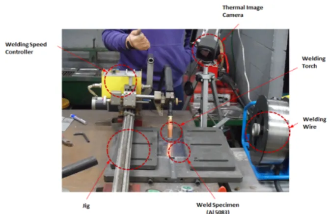
For this study, the investigation as to welding condition through CO2 welding was performed to acquire the welding condition to minimize thermal deformation. CO2 welding is a method of semi-automatic welding to weld the weld parts by using the heat from arc-discharge between the base metal and weld torch at the atmosphere of the shield gas such as of CO2. For CO2 welding, a flux cored wire where flux is cored inside is normally used. Autocarriage type of CO2 welding de- vice that is attached with ‘welding speed controller’ was uti- lized, and then data for the temperature distribution along the change of time was obtained by using ‘thiermal image cam- era’.
Table 1: Chemical composition and mechnical properties of Al 5083
Si Mn Mg Al Tensile St. Elong.
< 0.4 0.4~0.5 4.0~4.5 Base 290MPa 10~15%
Weld specimen of Al 5083 (5083-O) was manufactured for the size of 1000 × 2000 × 3 (mm) and CO2 welding machine of 500A level was used. The chemical composition and main mechanical properties of the used specimen in this study are shown in Table 1.
Figure 1: Actual view of autocarriage type of CO2
welding test equipment used in this study
With respect to the procedure of welding operation, the ap- plied welding condition (150 A, 16 V at the welding speed of 6 mm/sec) was primarily set up. Then, when the start button was pushed, the speed that was set prior to welding was main- tained constantly and welding for Al specimen was carried out.
Such a process was measured at time interval by using thermal image camera and the data for temperature distribution along the change of time was obtained at the measuring points which were set up. Autocarriage type of CO2 welding device and rel- evant components used for thermal deformation-related test analysis in this study are shown in Figure 1. And the actual image of welding speed controller and thermal image camera (model name : Thermal CAM P25) is shown in Figure 2.
GMAW (gas metal arc welding) is usually called MIG (metal inert gas) and frequently used for high productivity and efficiency in the fields of welding industry. On the other hand, this welding method is limited to be applied to CO2
semi-automatic welding because of lots of welding spatters.
However, GMAW robot is often used for high productivity as the proper current, voltage and welding speed was applied. In relation to welding methods for Al 5083 alloy, many cautions are to be required and an enough review prior to welding op- eration might be necessary.
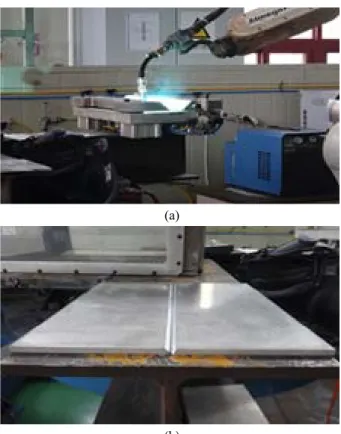
(a)
(b)
Figure 3: Actual image of MIG robot operation(a) and pre- pared Al 5083 specimen on operation(b)
In addition to the above thermal deformation-related test analysis, welding operation by using MIG robot under the various welding conditions was conducted in order to the effect of welding conditions on the tensile characteristics of Al 5083 nonferrous alloy applied to co-environmental lea- sure ships. An actual image of MIG robot operation and prepared specimen for welding is shown in Figure 3. Then, various welding conditions, specimen thickness and specimen quantity used for welding operation are indicated in the be- low Table 2. For the case of tensile specimens, the standard of 25 mm in width and 50 mm in mark distance (25 x 50 mm) was applied as to GMAW welding parts, according to the KS standards for tensile specimens.
Table 2: Welding conditions of Al5083 MIG welding No. Current
(A)
Voltage (V)
Welding Speed (m/min)
Thickness (T)
Torch Angle (°)
Amount of specimens
No.1 130 15.5 0.7 5T 0° 5EA
No.2 150 16.5 1.0 5T 0° 5EA
No.3 170 18.5 1.5 5T 0° 5EA
No.4 170 19.0 0.7 10T 0° 5EA
No.5 190 20.5 1.0 10T 0° 5EA
No.6 210 21.5 1.5 10T 0° 5EA
3. Test analysis and consideration 3.1 Data analysis related to thermal deformation
In order to obtain the welding operation condition to mini- mize thermal deformation, autocarriage type of CO2 welding device that is accompanied with ‘welding speed controller’
was utilized, and then the data for the temperature distribution along the change of time was obtained by using ‘thermal im- age camera (model name : Thermal CAM P25). In this proc- ess, investigation for actual relevant data was carried out for the purpose of acquiring the welding condition(current, volt- age, welding speed) to minimize thermal deformation and re- duce surface defects of Al base metal.
With respect to thermal deformation-related observation, the data for temperature distribution along the change of time (10
~ 40 sec) was obtained at the measuring points that was pre- viously set up (pre-marking). The measuring points to measure the variation of welding temperature are shown in Figure 4.
As seen from top of Al specimen, the measuring locations were set up at the right side on the basis of welding bead.
Total 12 locations were decided along X and Y direction and a constant distance was maintained. Then observation on the variation of temperature along time was conducted in each di- rection and distance.
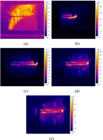
As seen in Figure 5, the temperature distribution along the variation of welding time was measured at intervals of con- stant time (10, 20, 30, 40 sec) by using thermal image camera. As a result of measuring the temperature distribution along the change of time on the basis of point located at X=15 mm, Y=25 mm, high temperature of flames from the instant arc-discharge were observed at an initial 10sec. Then temperature of flames showed the tendency to reduce along the change of time.
eco-environmental leisure ships
Figure 4: Schematic image of measuring points to inves- tigate variation of welding temp. verse welding time
(a) (b)
(c) (d)
(e)
Figure 5: Figures to be obtained from the observation of temp. distribution along variation of welding time (a) weld- ing to start, (b) 10 sec, (c) 20 sec, (d) 30 sec, (e) 40 sec
As a result of investigating the obtained resuts at individual measuring points, Figure 6 (a) is a curve of temperature dis- tribution along time in the X direction on the basis of Y=25 mm. As running autocarriage type of CO2 welding, welding temperature distribution showed the tendency to appear with an abrupt temperature rise of peak above 500 ℃ around 10
sec and gradually reduce along the change of time(10 ~ 40 sec), and finally maintain the constant temp. of 300 ℃. Here, the abrupt temperature rise means the ascending of temper- ature from the instant arc-discharge. Since welding operation at high temperature is followed by air cooling, a cooling proc- ess experiences a type of heat treatment pattern in step. Figure 6 (b) shows the temperature distribution along the change of time in the Y direction on the basis of X=15 mm, which in- dicates that the temperature distribution is being processed
‘sequently’ in accordance with a proceeding direction of weld- ing bead. As reviewing the curves in Figure 6, the temper- ature showed the tendency to increase with the initial, abrupt rise and steadily decrease along the change of time. Therefore, it can be revealed that the temperature distribution turns into a generally homogeneous process through a thermal equilibrium, which means thermal deformation is gradually reduced.
With respect to welding for engineering material such as Al, as thermal stress might takes place, constriction of plate and relevant phenomenon of twist might be observed at sight. In addition, internal stress like residual stress exists inside Al alloy in the process of welding. Actually, this kind of thermal and internal stress might bring the main cause to
(a)
(b)
Figure 6: Diagram to show the temperature distribution verse the change of time ; (a) several X-position (at Y=25 mm), (b) several Y-position (at X=15 mm)
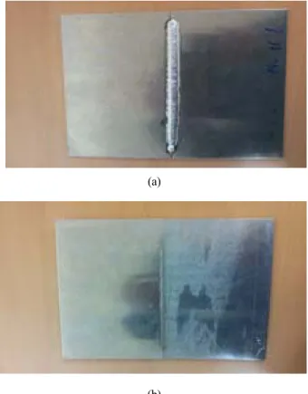
(a)
(b)
Figure 7: Actual image of welding bead on Al 5083 speci- men ; (a) welding part, (b) back bead
raise up thermal deformation and affect the Al product through material deformation of twist. Therefore, a technical review for welding conditions is required in order to minimize thermal deformation and prevent a dimension imperfection [7][8].
For the case of thermal deformation, namely a deformation that occurred out of the thermal stress as welding, it shows the tendency to be spheroidized as air cooling is processed af- ter welding. And the internal defects such as shrinkage and twist, in this process, might take place. This kind of process mainly belongs to thermal deformation. The shape of welding bead(surface and back bead) after the completion of autocar- riage type of CO2 welding for Al 5083 nonferrous alloy are shown in Figure 7. As shown in this figure, in case that the regulated current, voltage and welding speed was applied, there were no apparently thermal deformation and bead de- fects on the Al specimen [9][10].
Since the thermal deformation and the local shrinkage on the Al plate take place frequently, it was considered that the setting of the welding condition to minimize thermal deformation was very important. Actually, it could be taken into consideration that the proper welding condition to reduce the welding defects due to thermal deformation and minimize thermal deformation was 150 A, 16 V at the welding speed of 6 mm/sec.
3.2 Consideration for tensile characteristics
As a matter of fact, the welding technique applied to Al is GMAW (gas metal arc welding, MIG) including GTAW (gas tungsten arc welding, TIG). However, because TIG welding is mainly applied to the thin plate of Al alloy, MIG welding for the Al alloy with thick plate (5T, 10T) was carried out in this study. The welding operation by using MIG robot was con- ducted, in this research, and the Ar as inert gas was used for the shield gas as welding. In particular, an aluminium wire was utilized for the proper welding electrode. After conducting a GMAW welding operation for Al 5083 under the various welding conditions, the shapes of welding bead is shown in Figure 8, in comparison with each other per specimen thick- ness (5T, 10T) and the operation conditions. From this figure, the homogeneous shapes were generally seen and there were no surface defects on the specimens of Al 5083.
As observing the operation condition such as that in Table 1, GMAW welding was conducted and then tensile specimens
(a) (b)
(c) (d)
(e) (f)
Figure 8: View of various welding beads as to varying welding conditions
130 A x 15.5 V at 0.7 m/min (5T) : 5-1 150 A x 16.5 V at 1.0 m/min (5T) : 5-2 170 A x 18.5 V at 1.5 m/min (5T) : 5-3 170 A x 19.0 V at 0.7 m/min (10T) : 10-1 190 A x 20.5 V at 1.0 m/min(10T) : 10-2 210 A x 21.5 V at 1.5 m/min(10T) : 10-3
eco-environmental leisure ships for reviewing the purposed tensile characteristics were
manufactured. The standard of 25 mm in width and 50 mm in mark distance was applied for tensile specimens as to GMAW welding parts, according to the KS standards for tensile specimens. 5 specimens were prepared as to each welding condition, varying the thickness (5T, 10T), and then the ten- sile test was carried out at the speed of 5 mm/min (total amount of specimens : 30ea, 15ea for 5T and 15ea for 10T).
The results of tensile test after GMAW welding are shown in Table 3. As a result of the tensile test for Al 5083 tensile specimens, the relatively high tensile strength and elongation was obtained on the welding condition of 5-3 and 10-2. For the case of the specimen of 5-3 and 10-2, the coloring marks (blue color) were used, compared to other specimens.
With respect to the effect of welding condition on tensile characteristics of Al 5083 specimen with thickness of 5T (belonging to 5-1, 5-2 and 5-3), the yield strength and the ten- sile strength showed the tendency to relatively increase, as gradually increasing current, voltage and welding speed (130 <
150 < 170 A, 15.5 < 16.5 < 18.5 V, 0.7 < 1.0 < 1.5 mm/min). As reviewing the results of tensile test, the welding condition of 170 A, 18.5 V at the speed of 1.5 m/min was applied to Al specimen (belonging to 5-3) and the higher stress-strain curve was obtained in this case, showing 284.62 MPa of tensile strength and 11.41 % of elongation (for case of 10T, belonging to 10-2).
For the case Al 5083 alloy, it is used for material of weld- ing structure and shows the mechanical property such as 290MPa of tensile strength and 10~15 % of elongation as to the original base material. The normal tensile characteristic
Table 3: Tensile test results of Al 5083 Welding
Condition
Yield Stress(MPa)
Tensile stress(MPa)
Elongation (%)
5-1 (5mm) 149.14 259.82 8.34
5-2 (5mm) 150.38 278.13 11.77
5-3 (5mm) 155.61 284.62 11.41
10-1 (10mm) 149.21 270.93 10.37
10-2 (10mm) 152.85 282.88 11.12
10-3 (10mm) 159.72 268.53 9.13
Table 4: Normal, mechanical properties of Al 5083 Mechanical
property
Yield strength(MPa)
Tensile
strength(MPa) Elongation
Al 5083 145MPa 290MPa 10~15%
of Al 5083 prior to welding is shown in Table 4, which ex- plains that the majority of tensile specimens after welding op- eration shows mostly more than 80 % of tensile strength val- ue, compared to that of the original material.
In this study, as cutting out the tensile specimens from the welding specimen, those were prepared to make sure that weld metal is located at the center of tensile specimen and cut out perpendicular to the weld metal. In case of the specimens af- ter welding operation, most of weld metals show the hardness values higher than that of the base metal. However, the heat affected zone (HAZ) is located between the weld metal and the base metal and belongs to the most weaker part. Due to this reason, the weld part which is broken up primarily is the heat affected zone. Therefore, the fracture under the tensile test might take place in HAZ and shows the value of tensile strength less than that of the base metal. As shown in Figure 9, the internal microstructure of weld specimen can be ob- served as magnifying the weld specimen by using of SEM (scanning electron microscope). In case that the structural de- fects after welding operation take place, the heat affected zone belongs to the part having the relevant defects. Especially, when some welding structure is inevitable to welding oper- ation, the HAZ can plays a main role in deciding a design parameter. Furthermore, if the tensile specimens are cut out from the weld metal, parallel to welding direction, and tested under the given tensile condition, those are supposed to show the value of tensile strength higher than that of the base metal [11].
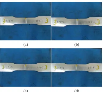
For the case of the specimens of 5-3 and 10-2 which showed the relatively superior tensile characteristics, the each specific dimensions as to thickness (T) and width (W) of tensile specimen are shown, respectively. The individual shapes of specimens after tensile test were shown in Figure 10 and Figure 11 for the purpose of investigating the specific site where the fracture took place.
Figure 9: The SEM image for internal structure of weld specimen; weld metal, heat affected zone, base metal
(a) (b)
(c) (d)
Figure 10: View of various tensile specimens as to the welding conditions: 170A x 18.5V at 1.5m/min (5T); 5-3 (a) 4.05 T x 24.5W, (b) 4.12T x 24.45W,
(c) 4.11T x 24.50W, (d) 4.01T x 24.57W
(a) (b)
(c) (d)
Figure 11: Various tensile specimens as to the welding conditions: 190 A x 20.5 V at 1.0 m/min(10T); 10-2 (a) 8.99T x 24.47W, (b) 8.99T x 24.49W,
(c) 8.81T x 24.46W, (d) 8.93T x 24.45W
As shown in the results of tensile test, most of fractures ex- cept for the case of 10-3 took place in HAZ in the process of tensile test, but the fracture for the case of 10-3 occurred in the weld metal as tensile-tested (refer to the red mark ellipse in Figure 12). As shown in the case of 10-3, the reason why the fracture occurred in the weld metal showing normally the higher tensile value is because the welding condition belonged to the improper welding one. Since the welding speed for the case of 10-3 was too fast, in comparison with current and
(a) (b)
(c) (d)
Figure 12: Various tensile specimens as to the welding conditions: 210 A x 21.5 V at 1.5 m/min(10T); 10-3 (a) 8.94T x 24.47W, (b) 8.83T x 24.46W,
(c) 8.93T x 24.49W, (d) 8.92T x 24.46W
voltage, the welding operation was not performed enough.
Here, in case that welding was conducted under the welding condition of 5-3 and 10-2, the tensile strength almost close to that of the Al 5083 base metal could be obtained and it showed the allowable tensile strength that is actually applied to manufacturing of eco-environmental Al leisure ships.
In brief summary, MIG welding was carried out under the various welding conditions at the inert gas atmosphere by di- viding welding specimens into two types (5T, 10T). And as a result of tensile test at the speed of 5 mm/min, the majority of fractures took place in the HAZ adjacent to the weld metal except for some cases. This means that MIG welding is avail- able in Al 5083 alloy in the given conditions and more than 80% of tensile strength, compared to that of the base material was obtained on the HAZ through the tensile test showing the mechanical properties.
As investigating the results of tensile curves through the tensile test, the typical tensile load-strain curves were obtained on the specimens with thickness of 5T and 10T as shown in Figure 13 (a) and Figure 13 (b). In the case of Figure 13 (a), it is a type of tensile load-strain curve over the specimens with 10T (#1 ~ #15) where yield points were observed and 60 KN of mean tensile load was obtained. Considering the mean sectional area is 220 mm² where the back bead was removed for obtaining the sectional area, the mean tensile strength showed approximately 270 MPa.
For the case of Figure 13 (b), it shows the tensile load-strain curve over the specimens with 5T (#16 ~ #30)
eco-environmental leisure ships
(a)
(b)
Figure 13: Diagram to show the results of tensile tests for Al 5083 as to various welding conditions (a) specimen #1 to #15, (b) specimen #16 to #30
where 30 KN of mean tensile load was obtained as a half of the tensile load in Figure 13 (a). Here, considering the mean sectional area is 110 mm², the mean tensile strength showed 270 MPa almost close to that in Figure 13 (a). Namely, since the width of specimen is almost the same but the thickness is different (5T, 10T), it was taken into consideration that the sectional area (width × thickness) plays a significant role as deciding the tensile strength, as a main parameter. In brief, as obtaining the tensile curve on the basis of tensile load (kN), two types (5T, 10T) of tensile curves showed different shapes of curves. However, as converting to the results on the basis of tensile strength (MPa), both of the curves showed the sim- ilar tensile behavior in the aspect that the mean tensile strength was almost the same.
3.3 Consideration for weld deformation by minimizing thermal deformation
Differently to the above mentioned behaviors of thermal de- formation and tensile characteristics, the prototype of Al boat might be manufactured in the experimental research, not for the specimen for test. This was achieved for the purpose of
examining the weld deformation after welding operation in the process of manufacturing the prototype of boat by using Al alloy material. And several problems appeared as welding by junction of Al alloy. Importantly, as welding for 3 dimen- sional prototype of boat, not the test specimen, several un- expected results on welding beads apparently were obtained and the weld deformation where the shape of Al prototype is slightly twisted at the particular welding part could be ob- served(refer to Figure 14).
In relation to the unstable parts on the welding bead, it be- longed to the case that the current and voltage was out of the regulated value. And in the case that the porosity was for- mulated on the weld parts, it was revealed that the welding speed was not constant. When an autocarriage type of car- bon-dioxide welding machine was used on the specimen for reviewing the behavior of thermal deformation, a quite stable welding method may be applied. However, because a semi-au- tomatic arc welding was conducted for this test operation, some welding defects like undercut and spatter frequently took place. Furthermore, it was estimated that some homogeneous welding speed was hard to acquire for the requirements of suitable welding condition.
Figure 14: Actual prototype image for Al 5083 co-environ- mental boat discussed in this study
In fact, there are overlap, spatter, incomplete penetration and undercut with respect to the extraordinary phenomena as welding. When a current is low and the welding speed is slow, overlap takes place, while incomplete penetration ap- pears in the condition of low voltage and slow welding speed.
On the other hand, when a voltage is high and the welding speed is fast, welding defect such as spatter takes place, while undercut does in the condition of high current and fast weld- ing speed. Therefore, it is considered that the proper welding condition was required to prevent the welding defects on welding bead. Actually, the welding procedure specification
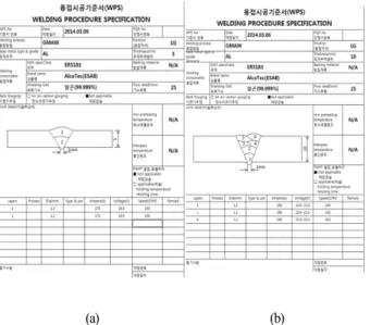
for Al 5083 that is applied to the operation fields is shown in Figure 15 and this WPS belongs to the procedure obtained from welding by varying the welding conditions over the specimens with 5T and 10T.
(a) (b)
Figure 15: Types of WPS applied to the work fields ; (a) 170 A x 18.5 V at 1.5 m/min (5T),
(b) 190 A x 20.5 V at 1.0 m/min (10T)
Furthermore, an additional operation of post-heat treatment such as ‘straightening’ was required to reduce a material de- fect like twist from thermal deformation and prevent a possi- ble dimension imperfection. Usually, a post-heat treatment like
‘straightening’ is omitted in the process owing to the reason of cost saving and process-hour shortening. However, even though it requires a constant time and cost, post-weld heat treatment is quite effective in reducing thermal deformation and has the advantage to repair ‘instantly’ at some local parts.
On the other hand, it has the pre-requirement to require a technical and sophisticated engineer for heat treatment.
4. Conclusions
In relation to the effect of welding conditions on the behav- ior of thermal deformation and the tensile property of Al 5083 alloy applied to eco-environmental Al leisure ships, the major conclusions drawn from the study are as follows:
(1) As a result of investigating a temperature distribution along the variation of time after setting measuring points, as running autocarriage type of CO2 welding, welding temperature distribution showed the tendency to appear with an abrupt temperature rise of peak above
500 ℃ around 10 sec and gradually reduce along the change of time, and finally maintain the constant temp.
of 300 ℃.
(2) In case of performing autocarriage type of CO2 weld- ing, the optimum welding condition to reduce defects by thermal deformation and minimize thermal deforma- tion was revealed to be 150 A and 16 V at the welding speed of 6 mm/sec which belongs to a rather slower speed.
(3) With respect to MIG (metal inert gas) welding under in- ert gas atmosphere varying welding condition, most of fractures took place on HAZ (heat affected zone) ad- jacent to weld metal after performing tensile test at the speed of 5 mm/min by dividing specimens into two types of thickness (5T, 10T). In addition, more than 80% of tensile strength value was shown as an actually allowable tensile one.
(4) As a result of performing tensile test after MIG welding by varying the welding condition (current, voltage and welding speed, etc.), a higher stress-strain curve with 284.62 MPa of tensile strength and 11.41% of elonga- tion was obtained as conducting welding for the speci- men with thickness of 5T on the condition of 170 A, 18.5 V at the welding speed of 1.5 m/min, compared to other welding conditions.
(5) From this study, it was revealed that the optimum weld- ing conditions related to thermal deformation and tensile property might be used in the process of conducting welding for Al 5083. Furthermore, an additional oper- ation of post-heat treatment such as straightening was required to reduce a material defect like twist from thermal deformation and prevent a dimension imperfection.
Acknowledgement
This research was conducted by the assistance of a human resources training project for regional innovation, Korea Research Foundation (No. 2013H1B8A2023237) and a Eco-sys- tem Support Project for Honnam broad area leading industry.
References
[1] Society of the Fusion Welding of Light Metals, Inert Gas Welding of Aluminium Alloys, Japan Light Welding Association, Tokyo, 1971.
[2] T. Gurney, Cumulative Damage of Welded Joints, Woodhead Publishing Limited, Oxford, 2006.
[3] H. J. Kweon and J. H. Lim, General Welding
eco-environmental leisure ships Engineering., Seon Hak Press, Incheon, 2003 (in
Korean).
[4] L. F. Monodolfo, Aluminium Alloy : Structure and Properties, Butterworths, London, 1976.
[5] J. Nutting and R. G. Baker, The Microstructure of Metals, Institute of Metals, London, 1965.
[6] T. R. Gurney, Fatigue of Welded Structures.
Cambridge University Press, Cambridge, 1968.
[7] G. J. Davies, Solidification and Casting, Wiley, New York, 1973.
[8] M. C. Flemings, Solidification Processing, McGraw-Hill, New York, 1974.
[9] S. Kou, Welding Metallurgy, A John Willey & Sons, Inc., New York, 2003.
[10] W. F. Smith, Structure and Properties of Engineering Alloys, McGraw-Hill, New York, 1981.
[11] K. Masubuchi, Analysis of Welded Structures, Pergamon, Elmsford, New York, 1980.