Reader Collision Avoidance Scheme for Mobile RFID-Sensor Integrated Networks
Doo-Hyun Ko* , Song-Min Kim* , Sang-Bin Lee , Sun-Shin An*★
Abstract
In recent years, one of alternatives for constructing RFID networks that provide mobile services is using wireless sensor networks (WSN) to enhance network capacity, utility and scalability. Due to absence of compatible reader anti-collision control and channel capture phenomenon, the medium access control protocols as used in the RFID networks lead to reader collision and starvation problem. In this paper, we develop a MAC protocol which is called Enhanced Collision Avoidance MAC (ECO) to avoid reader to reader collisions in an integrated RFID network. ECO is a CSMA-based MAC protocol, and operates on integrated nodes which consist of a RFID reader and a mote. Performance evaluation shows superior results to pure-CSMA protocols under dense deployment environments, both in number of failures and in throughput.
Key words: MAC, WSN, RFID, Network
This work was supported by the second stage of the Brain Korea 21 Project in 2009.
* Student, Dept. of Electronics Engineering, Korea University
★ Professor, Dept. of Electronics Engineering, Korea University
※ Acknowledgment
Manuscript received Jan. 15, 2009; revised May. 25, 2009
I. Introduction
As electronics and communication technologies advance, wireless communication system has been accomplished incredible growth, and major devices also are became smaller and smarter. This advance will elevate computing systems, and it will be not easy to find the ubiquitous system in daily lives.
One of the key technologies for ubiquitous computing is radio frequency identification (RFID) which is a data-collection technology that uses radio waves to remotely store and to retrieve data to identify various objects. It provides companies with up-to-the-minute supply chins visibility,
including inventory, logistics and freshness dates.
Recently, RFID is increasingly being used in many applications and services such as inventory management, object tracking, commuting check etc.
For example, KLM/Air France implemented RFID-enabled baggage tags inside Amsterdam Airport, and Google India a division of search engine company Google, is using an RFID system to track up to 100,000 of its assets at its offices.
However, as RFID systems and mobile RFID services increases, data management is more important and complicated. Consequently, RFID systems should be managed with networks for efficient data collection and transmission. One of alternatives for constructing RFID networks is using wireless sensor networks (WSN). Although monitoring of the surrounding physical environment is indispensable in the management of environment-sensitive objects, existing RFID networks and services lack this capacity. The environmental information of RFID networks, such as temperature and humidity is also not available.
In this cases, the surrounding conditions can be
learned through wireless sensor networks (WSNs), which are wireless networks consisting of spatially distributed autonomous devices using sensors to cooperatively monitor physical or environmental conditions, such as temperature, sound, vibration, pressure, motion or pollutants, at different locations.
WSNs were originally developed for military applications such as battlefield surveillance.
However, WSNs are now used in many commercial areas, including environment and habitat monitoring, healthcare applications, home automation, and traffic control. Capacities of WSNs are also very powerful as a network, because WSNs not only support data collection but also provide routing, aggregation and analysis of information. Furthermore, WSNs are considerably attractive when constructing RFID networks due to their high compatibility with other networks. To complement defects of RFID networks, they will ultimately need to combine with WSNs. In SARIF [3], it illustrates well a framework for integrating wireless sensor and RFID networks.
They proposed a novel framework, SARIF (sensor and RFID integration framework), that integrates
RFID networks and WSNs for
environment-sensitive object tracking and management, and proved that SARIF can achieve energy efficiency by load balancing. But integrated RFID still remain to solve several problems. One of them is the collision problem that is arisen between tags and readers. Currently, common solutions exist for tag-tag collision, and reader-tag collision has been also studied in the EPC-Grobal Class1 Gen1 and Gen2 standards for UHF readers. However, although there are some algorithm for reader-reader collision such as Colorwave [4], PULSE [5] and IRCD [6] etc, these algorithms are not solutions for sensor and RFID integration framework.
Consequently, we focus on reader-to-reader collision avoidance scheme for integrated RFID-sensor networks.
In this paper, we propose an integrated RFID-sensor networks architecture that enables an application to be designed flexibly while hiding the details of the RFID networks and WSNs. And we discuss a scheme to avoid collisions in multi reader scenarios.
II. System Design for Mobile RFID-sensor Networks
In this section, we propose an architecture of integrated RFID-sensor networks in a mobile environment. Our network structure can provide a remote monitoring service and a mobile terminal service. Currently, it is possible to get information of products from mobile terminals. This service is using cellular networks, in which a reader is embedded in a mobile phone, and if the reader read a tag, the mobile can get information from tag’s data via cellular network. However, it is the restrictive service which is for only a mobile user.
The RFID system should be used various objects and provided with useful information. For example, if one consumer reads attached tags to buy fresh foods, it should be provide not only cost and date of manufacture but also temperature data in the storage. RFID system should also provide sensing information which is requested to control resource management. Consequently, by integrating RFID systems with WSNs, we can build an object tracking system and management system that can provide richer information about the environments of objects.
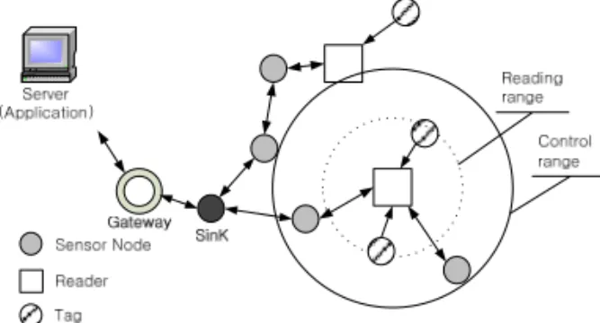
Fig. 1. RFID-sensor network architecture
II-I System Design and Service Model Fig 1 illustrates well a proposed network architecture. In this architecture, tags, sensor nodes and reader are coexisted in sensor network, where reader is integrated module interfaced with the sensor mote, The integrated module can be fixed or moving, and it can communicate with tags and sensor nodes, and it is detailed in next subsection.
If the integrated module read adjacent tags, its data
is transmitted to the sink via sensor networks, where the sink node collects not only sensing data but tags. the collected data is sent to server or application through core network. When clients request information to server, server provides appropriate information. This network structure can provide not only real-time service but also tracking and mobile services.
II-II Hardware Configuration
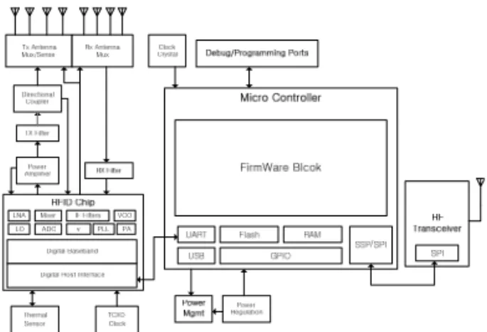
The integrated RFID-sensor module is consisted of three parts which are RFID reader (960MHz), micro-controller and RF transceiver (2.4GHz). We use the SkyeModule M7 (RFID reader module) which is globally compliant UHF module for embedded RFID. The read range of this reader is up to 1 meters with external antenna. It can communicate with a host micro-controller over the UART, SPI and I2C interfaces. The interface between microcontroller and reader parts is UART bus. The reader module is capable of responding to ASCII and binary commands sent by the host micro-controller. It can select, read and write tags. The host controller can also read and write the reader’s memory and system registers to put the reader in low power sleep mode and to wake it up from sleep. The small footprint and low power requirement makes it suitable to integrate RFID and sensor networks. A used RF transceiver is CC2420 which is known well in sensor network area. The CC2420 is a true single-chip 2.4 GHz IEEE 802.15.4 compliant RF transceiver designed for low-power and low-voltage wireless applications. CC2420 includes a digital direct sequence spread spectrum (DSSS) baseband modem providing a spreading gain of 9dB and an effective data rate of 250 kbps. It is also connected to micro-controller with SPI bus. This module is called as Ubicon. Fig 2 and 3 illustrate Ubicon and its block diagram.
Fig. 2. Ubicon version 1.0
Fig. 3. RFID -Sensor network platform
III. Enhanced Reader Collision Avoidance Scheme for Mobile
RFID-sensor Networks
In proposed network, we use the integrated module.
When the number of RFID readers is increased or when the module is moving, the probability of reader collision increases. Consequently, we have designed a medium access control protocol to avoid the reader collision problem. The protocol is discussed in this section. we propose CSMA-based reader control scheme for communication with WSNs, and we call this scheme as enhanced collision avoidance MAC (ECO).
III-I Reader Collision Problem
Simultaneous transmission in RFID systems lead to collisions as the readers and tags typically operate on the same channel. In this section. we will discuss about two interference types that are caused reader collisions before describing ECO.
A. Reader to Reader Interference
Reader-to-reader frequency interference, or simply frequency interference, occurs when a reader transmits a signal that interferes with the operation of another reader,
Fig. 4. Reader to Reader Interference
Fig. 5. Multiple Readers to Tags Interference
thus preventing the second reader from communicating with tags in its interrogation zone. This type of interference occurs when the signal transmitted by a reader is of sufficient strength when received at a second reader that the signal masks or jams communication from tags to the second reader. Interrogation zones need not overlap for reader-to-reader frequency interference to occur. The signal from the tag to the reader is extremely weak since tags communicate with readers by either reflecting or loading the reader’s own transmission. These signals are easily masked by transmissions from other nearby readers. For example, R1 lies in interference region of reader R2 in fig 4. The reflected signals reaching reader R1 from tags, can easily get distorted by signals from R2. Note that such interference is possible even when the read range of the two readers do not overlap.
B. Multiple Readers to Tag Interference Multiple reader-to-tag interference, or simply tag interference, occurs when one tag is simultaneously located in the interrogation zones of two or more readers and more than one reader attempts to communicate with
that tag at the same time. In this type of interference, each reader may believe it is the only reader communicating with the tag while the tag is in fact connected with multiple readers. In simple RFID networks, the protocol is implemented in an undesirable way that may interfere with the communicating readers’ abilities to communicate with that tag and other tags in their respective interrogation zones. In fig 5, the reading range
Fig. 6. Two-way handshake of RTR-PTR
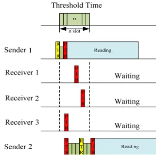
Fig. 7. Timing relationship between senders and different receivers
of the two readers is overlap. Hence the signals from R1
and R2 might interfere at tag T1. In this case, T1 cannot decipher any query and the tag is read neither by R1 nor by R2. In this case, R1 will indicate presence of two tags instead of three.
III-II Enhanced Reader Collision Avoidance MAC (ECO)
We have implemented enhanced collision avoidance MAC using the unslotted CSMA-CA algorithm. ECO is an asynchronous MAC for mobility service. We should also consider controlling both of channels when we design a
Begin ECO countRTR is zero:
1. if backoff == zero then 2. do broadcast RTR
3. wait PTRflag is TRUE or waitTerm
4. do read tags 5. else wait backoff until zero
6. end if
Received RTR:
1. if countRTR > zero then 2. do countRTR += 1 3. do waitTime += reading time 4. while waitTime != 0
5. do wait during reading time 6. end while
7. do countRTR -= 1
9. else
protocol, because our integrated module has two channels.
Refer to fig 6, ECO arbitrates the RFID-sensor networks with two-way handshake of RTR-PTR packets. The RTR packet means that a node (Ubicon) requests to read adjacent tags. The PTR packet is response of adjacent nodes for the RTR packet. The RTR packet includes several information such as reading time, transmitter's ID and etc. If one of Ubicons wants to read tags around, it broadcasts the RTR to other nodes. Nodes which receive the RTR packet send the PTR packet to permit reading, and then they fall in wait phase or sleep mode during reading time to guarantee reading of the RTR packet transmitter without collisions. When each node which has received the RTR broadcasts the PTR, they choose randomly one of n slots within threshold time to avoid collision of the PTR.
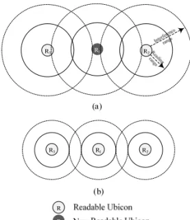
Fig. 8. Readable Ubicons after RTR-PTR packet handshake
Each slot is very short time compare to backoff. The node which sent the RTR, reads immediately tags, when the node receives first the PTR. If the node doesn’t receive PTR during threshold time, the node regards adjacent nodes as nothing; therefore, the node starts reading. It is illustrated in fig 7. The PTR packet is also used to give a reading chance to adjacent nodes. When the PTR is broadcasted, the nodes which received the PTR also choose randomly slot and send RTR message, if those want to read the tags. As this way, ECO increases the reading chance of nodes. Refer to fig 8, R1
that has the shortest backoff broadcasts the RTR packet after backoff time, and then adjacent R2, R3 and R4 that received the RTR packet send the PTR packets and store the ID of the transmitter in the RTR packet. Nodes (R5,7,8,9,10 and 11) which received the PTR packet also store the ID from PTR, and send again RTR packets. If these nodes don’t receive any other packets or receive the PTR
packet, these nodes also have simultaneously a chance which can read tags. R6 should sleep in reading time because it received the RTR from R5.
III-II-I ECO Algorithm Description Fig 10 shows the detailed algorithm for the ECO protocol. This description illustrates that our reader (Ubicon) is how to operate in the integrated network. countRTR is zero, where the countRTR is the number of received RTR, and when the backoff time is elapsed, Ubicon broadcasts the RTR and waits until receiving the PTR or waitTerm (threshold time). And then Ubicon reads tags through the UHF channel. If Ubicon completes reading tags, it goes into sleep mode. In state of Received RTR:, if already countRTR is larger than zero, Ubicon adds one in the countRTR, and waits until reading time is elapsed. Then Ubicon subtracts one from the countRTR. If the countRTR had been zero, backoff counter is stopped immediately, and broadcasts the PTR. At this time, The countRTR is set as one. Then Ubicon waits during reading time.
After that, if the countRTR is zero, Ubicon goes to countRTR is zero: state to get a reading chance.
If not, it goes to Received RTR: state. when the reader receives the PTR, it goes to Received PTR: state. In this state, the reader waits during backoff time, and if the countRTR is zero, goes to countRTR is zero: state to get reading chance, if not, goes to Received RTR: state.
10. do backoff counter stop 11. do broadcast PTR 12. do countRTR = 1 13. do waitTime = reading time 14. do wait during reading time
15. end if
16. if countRTR == zero then 17. goto countRTR is zero:
18. else goto Received RTR:
Received PTR:
1. waiting backoff
2. if countRTR == zero then 3. goto countRTR is zero 4. else goto Received RTR:
5. end if
begin power control
1. if countRTR > threshold then 2. goto DEC:
3. else if transFail == true 4. goto INC:
5. else if pwrCtrlMsg == true then 6. goto Received pwrCtrlMsg:
7. end if DEC:
1. do broadcasting pwrCtrlMsg 2. if Pcur != P1 then do Pcur = Pcur - 1 3. do countRTR = 0 INC:
1. if Pcur != PL then 2. do Pcur = Pcur + 1 Received pwrCtrlMsg:
1. if ctrlType == true then 2. goto DEC:
5. else
4. goto INC:
5. end if Fig. 9. Algorithm for ECO protocol
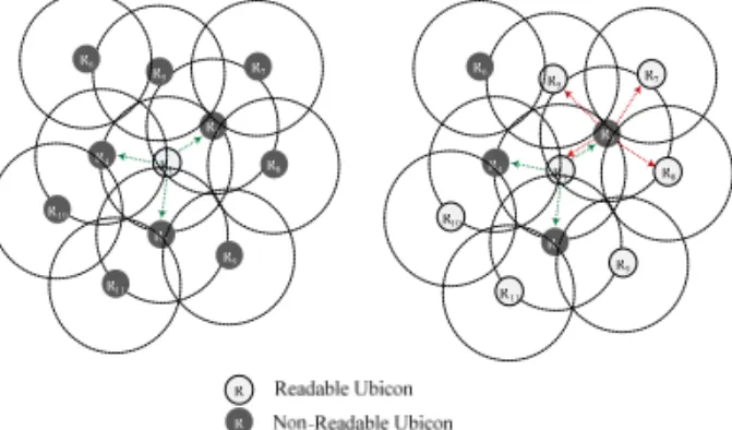
III-II-II ECO+: Power Control in ECO If the density of distribution of readers is high, it can lead to the channel capture because of mutual RTR packets. The channel capture effect happens when one node continues to "win" the link. This phenomenon is a cause of starvation problem. In this case, power control is one of methods which can mitigate effectively the capture problem. Power control can also offer better throughput because of spatial reuse. Consequently, we have designed ECO+ which executes power control in ECO. In fig 10 (a), R1 suffers from adjacent nodes R2, and R3 which have shorter backoff time than R1. At this time, R1
sends power control message to adjacent nodes with the control channel (2.4GHz), and nodes which receive this message turn down transmission power of both of reader and sensor. Fig 10 (b) shows readable nodes after power control.
Fig. 10. Power control in ECO
Fig. 11. Algorithm for power control of ECO+
Sending power control packet is decided by the number of received RTR of R1. In fig 11, our power control algorithm has power-levels from 1 to L, and the power at level i is denoted as Pi, where Pi∈
PA{P1, P2, P3, ⋯, PL} and PL is maximum power.
Whenever the reader receives consecutively the RTR packets more than threshold value, it goes to DEC: state and sends pwrCtrlMsg to adjacent
(1)
(2)
(3)
(4) nodes, then turns down its current power Pcur. Onthe other hand, power control can deteriorate link connectivity due to decreasing transmission power.
To avoid this problem, therefore, the reader should increase transmission power again. When the reader fails to send data because of disconnection with adjacent nodes, transFail is set TRUE. At this time, the reader goes to INC: state and increases its Pcur, and then sends pwrCtrlMsg. ctrlType variable in the received pwrCtrlMsg decides to increase or decrease transmission power. If ctrlType is TRUE., this pwrCtrlMsg is for decreasing power.
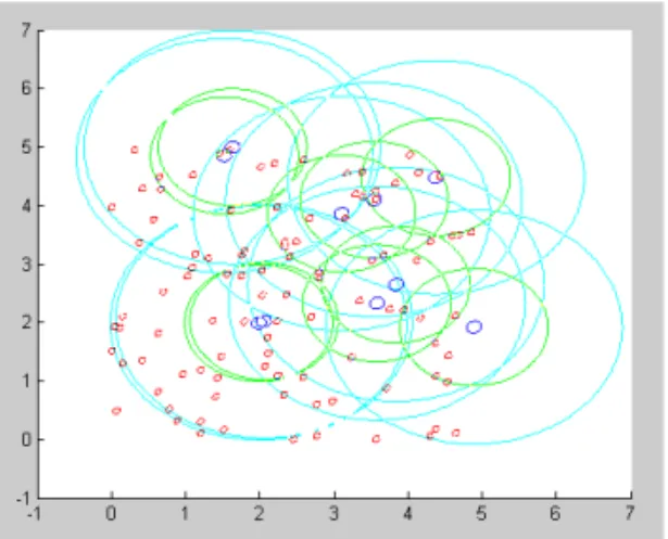
Fig. 12. The distribution of reader and tags in the simulation: blue circles are readers (Ubicon), red circles are tags, the green is reading range, and interference range is cyan.
IV. Performance Evaluation
In this section, we will describe our simulation environment and present performances of ECO and ECO+ through an analysis of simulation results.
IV-I Simulation Environment
Simulation has implemented using Matlab. In a square of 10 by 10 meters, nodes (Ubicon) are randomly uniform-distributed, while their antennae have omni-directional characteristics and transmission range is set to 2 meters. The number of tags is 1000, and the number of readers (Ubicons) is from 25 to 200. In the simulation, we distribute randomly readers and tags according to
uniform-distribution such as fig 12. We double the number of nodes each simulation. We use same topology and repeat 10000 times each simulation for fairness. The probability of traffic follows poisson-distribution. The reading time in ECO is assumed to be
where Rt and Mt are reading time and marginal time respectively. T1 is the time from interrogator transmission to tag response, and T2 is the interrogator response time required if a tag is to demodulate the interrogator signal, measured from the last falling edge of the last bit of the tag response to the first falling edge of the interrogator transmission. RTcal is interrogator to tag calibration symbol. TRcal is tag to interrogator calibration symbol.
Further details are stated in EPC spec [1]. Table 1 shows the characteristics of the node in integrated networks. Simulation is completed when all readers finish reading.
IV-II Simulation Result
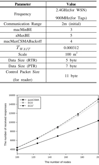
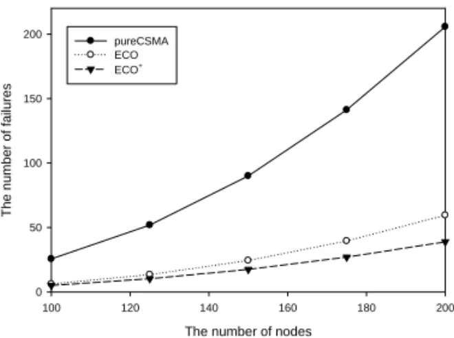
Fig 13 shows the simulation result of the number of received responses as the number of nodes increases. ECO and ECO+ have read more many tags than pure-CSMA. In fig 14, ECO and ECO+ take longer total reading completion time than pure-CSMA protocol, as a tradeoff of enhanced stability. Refer to fig 15, the number of failures of ECO and ECO+ are lower than pure-CSMA, and it proves that almost every node is able to read tags.
The throughput is calculated by
where, Ri is the number of responses which node i receives from tags. Pure-CSMA has more failures than others. However, total reading complete time of pure-CSMA is also shorter than others, these results also
influence in throughput by equation (4). Although ECO and ECO+ have longer total reading completion time than pure-CSMA, these take better throughput than pure-CSMA in fig 16.
Table. 1. Characteristics of Ubicon in the simulation environment
Parameter Value
Frequency
2.4GHz(for WSN) 900MHz(for Tags) Communication Range 2m (initial)
macMinBE 3
aMaxBE 5
macMaxCSMABackoff 4
0.000312
Scale 100 m2
Data Size (RTR) 5 byte
Data Size (PTR) 7 byte
Control Packet Size (for reader)
11 byte
The number of nodes
100 120 140 160 180 200
The number of received responses
4000 6000 8000 10000 12000 14000 16000
pureCSMA ECO ECO+
Fig. 13. The number of nodes Vs. The number of received queries
The nubmer of nodes
100 120 140 160 180 200
Total reading completion time (s)
0.02 0.03 0.04 0.05
pureCSMA ECO ECO+
Fig. 14. The number of nodes Vs. Total reading completion time
In every way, ECO+ performance is better than ECO according to density increases, and it proves necessity of power control in dense networks. Moreover, the lowest failure and the best throughput achieved by ECO+ guarantees improvements in the channel capture and spatial reuse.
V. Conclusion
We proposed an enhanced collision avoidance MAC protocol for the integrated RFID-WSN networks.
The goal of our proposal is to integrate RFID and WSN, and to avoid reader collisions in this networks. For the network integration, we have designed the integrated network architecture and an integrated module (Ubicon). In the proposed network architecture, sensor-nodes, tags and reader coexist, and the Ubicon arbitrates communication of these components. Ubicon is a sensor-node and a reader interfaced unit. It can communicate not only with sensor-nodes and readers but also can read tags.
The number of nodes
100 120 140 160 180 200
The number of failures
0 50 100 150
200 pureCSMA
ECO ECO+
Fig. 15. The number of nodes Vs. The number of failures
The number of nodes
100 120 140 160 180 200
Throughput
0 500 1000 1500 2000 2500
pureCSMA ECO ECO+
Fig. 16. The number of nodes Vs. Throughput
The Ubicon enables the integrated network to perform required functions such as ad-hoc, routing, aggregation and environment sensing. These functions enhance capacities of RFID networks. In addition, we implemented ECO for efficient communication without reader collisions. ECO is CSMA-based MAC protocol using two-way handshake, enables several nodes to simultaneously read tags without collision. We also adopted power control mechanism to mitigate the channel capture phenomenon. As a result, when we compared ECO and ECO+ with pure-CSMA, throughput was increased by 9.8% and 14.6%, respectively, and the best throughput and the lowest failure shows that
ECO+ can efficiently break starvation.
References
[1] EPC Radio-Frequency Identity Protocols Class-1 Generation-2 UHF RFID Protocol for Communication at 860MHz – 960MHz Version 1.1.0., Dec. 2005.
[2] IEEE std. 802. 15. 5-2003: Wireless Medium Access Control (MAC) and Physical Layer (PHY) specification for Low Rate Wireless Personal Area Networks (LR-WPANs)
http://standards.ieee.org/getieee802/download/802.15.4-2 003.pdf
[3] Jaekyu Cho, Yoonbo Shim, Taekyoung Kwon, Yanghee Choi, Sngheon Pack and Sooyeon Kim.
"SARIF: A Novel Framework for Integrating Wireless Sensor and RFID Networks." IEEE Transactions on wireless Communications, 14:50-56, 2007.
[4] J. Waldrop, D. W. Engels, and S. E. Sanna.
"Colorwave: a MAC for RFID reader networks." In IEEE Wireless Communications and Networking Conference (WCNC), New Orleans, Louisiana, USA, 2003, pp. 1701-1704.
[5] Shailesh M. Birari andSridhar Iyer. "PULSE: A MAC Protocol for RFID Networks." 1st International Workshop on RFID and Ubiquitous Sensor Networks (USN), Nagasaki, Japan, Dec 2005.
[6] Shijie Zhou, Zongwei Luo, Edward Wong, C. J.
tan and Jaiqing Luo. "Interconnected RFID Reader Collision Model and its Application in Reader Anti-Collision", In IEEE International Conference on RFID. Grapevine, TX, USA, Mar 2007.
[7] L. Zhang and Z. Wang, "Integration of RFID into Wireless Sensor Networks: Architecture, Opportunities and Challenging Problems", in: Proc.
of Grid and Cooperative Comp. Wksps., Oct 2006.
[8] ETSI EN 302 208-1 v1.1.1, Sep 2004 CTAN:
http://www.etsi.org.
[9] ETSI EN 302 208-2 v1.1.1, Sep 2004 CTAN:
http://www.etsi.org.
[10] Junius K. Ho. "Solving the reader collision problem with a hierarchical q-learning algorithm", Master’s thesis, Massachusetts Institute of Technology, Feb 20037.
[11] T. ElBatt and A. Ephremides. "Joint scheduling and power control for wireless ad hoc networks."
IEEE Transactions on Wireless Communications, 1:74 –85, 2004.
BIOGRAPHY
Doo-Hyun Ko (Student Member)
2007 : BS degree in Electrical Engineering, Kangnam University.
2009 : MS degree in
Telecommunication System Technology, Korea University.
2005~2006:Research Engineer, KETI.
2007~ : Ph.D course, Electronics Engineering, Korea University.
Song-Min Kim (Non Member) 2007 : BS degree in
Electronics Engineering, Korea University.
2007~ : MS Candidate, Electronics Engineering, Korea University.
Sang-Bin Lee (Non Member)
2004 : BS degree in
Electronics Engineering, Korea University.
2006 : BS degree in
Electronics Engineering, Korea University.
2006~ : Ph.D course, Electronics Engineering, Korea University.
Sun-Shin An (Non Member)
1973 : BS degree in, Seoul University.
1975 : MS degree in
Electronics Engineering, KAIST University.
1979 : Ph.D degree in Electric and Information, ENSEEIHT.
1982~ : Professor of Electronics Engineering, Korea University