반도체디스플레이기술학회지 제17권 제1호(2018년 3월) Journal of the Semiconductor & Display Technology, Vol. 17, No. 1. March 2018.
Relaxation of Singular Stress in Adhesively Bonded Joint at High Temperature
Sang Soon Lee
*†*†
Korea University of Technology and Education, School of Mechatronics Engineering
ABSTRACT
This paper deals with the relaxation of singular stresses developed in an epoxy adhesive at high temperature. The interface stresses are analyzed using BEM. The adhesive employed in this study is an epoxy which can be cured at room temperature. The adhesive is assumed to be linearly viscoelastic. First, the distribution of the interface stresses developed in the adhesive layer under the uniform tensile stress has been calculated. The singular stress has been observed near the interface corner. Such singular stresses near the interface corner may cause epoxy layer separated from adherent. Second, the interfacial thermal stress has been investigated. The uniform temperature rise can relieve the stress level developed in the adhesive layer under the external loading, which can be viewed as an advantage of thermal loading. It is also obvious that temperature rise reduces the bonding strength of the adhesive layer.
Experimental evaluation is required to assess a trade-off between the advantageous and deleterious effects of temperature.
Key Words : Epoxy, Adhesively Bonded Joint, Thermal Loading, Relaxation of Stress, BEM
1. Introduction
1
Adhesively bonded joints are extensively used in engineering structures. Polymeric adhesive such as an epoxy are widely used in electronic industry as adhesive layers [1]. The loads acting on the adhesively bonded joints are transferred through the adhesive mainly in tension or shear in certain circumstances. These layers may be damaged through a temperature change and resultant stresses can reach significant levels, possibly leading to interface debonding or delamination. Thus, prediction of the bond strength plays an important role at the design stage.
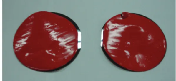
Fig. 1 shows epoxy layers separated from wafer substrates. When the temperature change occurs, adhesion of epoxy layer to substrates such as wafer tends to fall off.
Polymeric films deposited on a substrate can be subjected to thermal stresses due to the differences between the
†
E-mail: [email protected]
thermal expansion coefficients of the components. The deformation of the film is constrained by the substrate, and hence thermal stresses are built up in the film. Such thermal stresses can play a very important role during subsequent loading of the film/substrate system. Such thermal stresses may cause premature failure upon external loading.
Structural adhesives exhibit some sort of viscoelastic behavior at high temperature. The redistribution of stress in an adhesively bonded joint during viscoelastic deformation influences considerably the strength of the joints. It is well known that the interface of bonded quarter planes suffers from a stress system in the vicinity of the free surface under the external loading [2,3]. In such a region two interacting free surface effects occur, and singular interface stresses can be produced.
The time-dependent behavior of adhesive joints has been studied by several investigators. Hayashi [4]
analyzed the creep properties for a double lap joint. Delale
and Erdogan [5] employed the Laplace transform method
Sang Soon Lee 36
and presented the viscoelastic behavior of an adhesively bonded lap joint. Hu et al. [6] analyzed the viscoplastic behavior of a single-lap joint using a finite element method.
Lee [7,8] performed the boundary element analysis of the stress singularity for the viscoelastic adhesive layer.
There are various types of adhesive bonded joint, e.g.
single-lap joints, double-lap joints, single-strap joints, double-strap joints, scarf joints, stepped joints and tapered joints, etc. In this study, the singular stresses developed at the interface corner of adhesively bonded joints are investigated in tension. The adhesive used in this study is a polymeric epoxy which can be cured at room temperature.
The adhesive is assumed to be linearly viscoelastic. The adherent is assumed to be rigid as it is much stiffer than the adhesive. The detailed analysis is performed by using the boundary element method (BEM).
Fig. 1. Epoxy layers separated from wafer substrates.
2. Stress Singularity Induced in Adhesive Layer
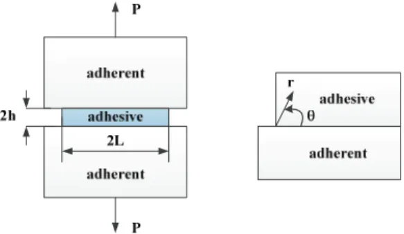
The order of the stress singularity at the interface corner of the adhesively bonded joint can be determined using a method similar to that described in Ref. [7,8]. Fig. 2 shows the region near the interface corner between perfectly bonded viscoelastic and rigid planes. The free surfaces are assumed to be traction-free.
In the following, a condition of plane strain is considered. A solution of
0 )
; ,
4
(
r t (1) is to be found such that the normal stress,
, and shear stress,
r,vanish along
2
, further that the displacements are zero across the common interface line
0
. In Eq. 1, t represents time.
The solution of this problem is facilitated by the Laplace transform, defined as
e dt t r s
r
st
0
*
( , ; ) ( , ; ) (2)
where
*denotes the Laplace transform of and s is the transform parameter. Then Eq. 1 can be rewritten using Eq. 2 as follows:
0 ) : ,
*
(
4
r s (3)
Using a method similar to that described by Lee [7,8], the transformed characteristic equation is obtained as follows:
0 ) cos(
) ( 3 4
) 5 ( 12 )
*( 2 8
* 2 * 2
s s
s s s
s p (4)
where is the stress singularity.
*( s ) is Laplace transform of the viscoelastic Poisson’s ratio ( t ) .
The adhesive considered here is characterized by a tensile relaxation modulus and an elastic bulk modulus as follows:
i i
iE t t E
E ( )
14exp
0 1
(5)
k MPa t
K ( )
o 3 . 0 10
3(6)
where E ( t ) is a tensile relaxation modulus and K ( t ) is a bulk modulus. The values of E
iand
iare listed in Table 1. Introducing Eq. 5 and Eq. 6 into Eq. 4 and inverting the resulting equation, we have
3 4 ( ) cos( ) 0
5 ) ( 12 ) (
2
2 8 M t N t N t (7) where
i t e E E
E k ko E
K o E o t ko
M
i j i ij j i
o
i i o
14 1 14
1 2
2
3 2 2 6
1 6 ) 3 (
i
t
i i i
E e
t
14
21
(8)
Relaxation of Singular Stress in Adhesively Bonded Joint at High Temperature 37
it
i i
o o
o
o
E e
k k
E t k
N
146
11 6
) 3
( (9)
In Eq. 8,
1 1
1
j i
ij i
for i j (10)
1 1
1
i j
i
for i j (11)
The singularity at the interface corner has a form of r
1. Roots of Eq. 7 are of main interest. The calculation of the zeros of Eq. 7 can be carried out numerically for given values of material properties.
Fig. 2. Region near the interface corner.
3. Thermally Induced Stress
The thermal stress induced along the interface between the epoxy adhesive and the rigid adherent due to uniform temperature change is analyzed. The polymeric film is assumed to be a linear viscoelastic material and to be thermo-rheologically simple. The boundary element method is employed to investigate the behavior of interface stresses.
A uniform temperature change TH (t ) in the layer is equivalent to increasing the tractions by ( t ) n
j[9] where
) ( 3 )
( t K TH t
(12)
Here, K is the bulk modulus; n
jare the components of the unit outward normal to the boundary surface; and
is the coefficient of thermal expansion of the viscoelastic layer.
With a uniform thermal change in the layer, it is convenient to write the boundary integral equations with respect to reduced time , instead of real time t . Then, the boundary integral equations without any other body forces are written as follows [9]:
(13)
where u
jand t
jrepresent displacement and traction, and S is the boundary of the given domain. c
ij(y ) is dependent only upon the local geometry of the boundary.
The viscoelastic fundamental solutions, U
ij( y , y ;' ) and )
;' , ( y y
T
ij, can be obtained by applying the elastic- viscoelastic correspondence principle to Kelvin’s fundamental solutions of linear elasticity.
Eq. 13 can be solved in a step by step fashion in time by using the modified Simpson’s rule for the time integrals and employing the standard BEM for the surface integrals [9]. Solving Eq. 13 under boundary conditions leads to determination of all boundary displacements and tractions.
4. Numerical Results
A viscoelastic layer bonded to a rigid substrate is shown in Fig. 3. The polymeric layer has thickness h 2 and length 2 L . Due to symmetry, only one quarter of the layer needs to be modeled. Fig. 3 represents the two- dimensional plane strain model for analysis of the interface stresses between the layer and the substrate.
Calculations are performed for L / h 10 .
In order to examine the viscoelastic behavior along the interface line of the layer, two examples are tested. First, the layer is assumed to be stress-free at a room temperature, and the uniform tensile stress
oalong AB provides the only loading. The boundary element discretization is employed. The refined mesh is used near the interface corner.
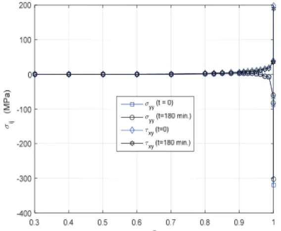
Fig. 4 shows the distribution of normal stress
yyand shear stress
xyon the interface at times t 0 and
) ' ( ' '
) '
;' , ) ( ' ( ) 0
;' , ( ) (
) ' ( ' '
) '
;' , ) ( ' ,' ( ) 0
;' , ( ) ,' (
) ' ( ' '
) '
;' , ) ( ' ,' ( ) 0
;' , ( ) ,' (
) , ( ) (
0 0 0
y y y y
y
y y y y
y y y
y y y y
y y y
y y
d dS n U
U n
d dS t U
U t
d dS u T
T u
u c
S
ij j m
ij j S
ij j
ij j S
ij j
ij j
j ij
Sang Soon Lee 38
180
t min. The numerical results exhibit the interface stresses and large gradients are observed in the vicinity of the free surface. Such stress singularity dominates a very small region relative to layer thickness. Since exceedingly large stresses at the interface corner, however, cannot be borne by the adhesive layer, delamination or interfacial edge cracks can occur in the vicinity of a free surface.
Table 1. The constants of eq. 5
Fig. 3. Boundary element analysis model.
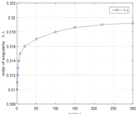
Fig. 5 shows the variation of the order of the singularity with the time for the material properties given by Eq. 5 and 6. Since the value of Poisson’s ratio of the layer
becomes greater with time, the order of the singularity increases with time.
Fig. 4. Distribution of interface normal stresses and shear stresses under the uniform tensile stress at time t=0 and t=180 min.
Fig. 5. Variation of the order of the singularity.
Second, the layer on the rigid adherent is assumed to be stress free, and is heated suddenly to high temperature.
The numerical values used in this example are as follows:
C T 100
o , 5 10
5/
oC (14) Fig. 6 shows the distribution of normal stress
yyand shear stress
xyon the interface at times t=0 and t = 180 min. The numerical results exhibit that the sign of the stresses is opposite, compared to Fig. 4. It can be seen that
i(min) E
i(MPa) 0.5 x 10
140.10817 E+03 0.5 x 10
130.5 x 10
120.5 x 10
110.5 x 10
100.5 x 10
90.5 x 10
80.5 x 10
70.5 x 10
60.5 x 10
50.5 x 10
40.5 x 10
30.5 x 10
20.5 x 10
0.12935 E+03
0.18168 E+03
0.23739 E+03
0.28994 E+03
0.32514 E+03
0.33116E+03
0.30568 E+03
0.25760 E+03
0.20145 E+03
0.14720 E+03
0.10934 E+03
0.48615 E+02
0.15854 E+03
E
o= 0.16876 E+03
Relaxation of Singular Stress in Adhesively Bonded Joint at High Temperature 39