A Comparison for Shear Resistant Behavior of Joints with Rock Bolt and Spiral Bolt Installed
– A Numerical Approach
M. K. Song and S. Y. Choo (Danwoo E&C Co., Ltd., Korea) S. S. Kang (Chosun National University, Gwangju, Korea) Y. D. Cho (Moojinneotech Co., Ltd., Korea)
1. INTRODUCTION
Spiral bolt, which is recently developed by Hirata et al.(2005), is rock bolt type support and has spiral shape of twisted the flat bar. Recent studies shows that support capacity of spiral bolt is superior to rock bolt owing to gearing effect of spiral shape, though the former has less cross sectional area(Song et al, 2007).
It is widely known that main function of rock bolt is to bind together stratified or broken rocks such as sedimentary rocks containing bedding planes, rocks consisting of natural joints and fractures, or rocks with fractures (Peng, 1984). By rock bolt, discontinuities can keep normal stress on surface, which results in maintaining its strength. However, in case the discontinuities tied with rock bolt have shear movement, then bolt also experiences the shear movement.
The failure of rock masses around excavation often occurred when the shear stress of joints and discontinuity are reached to its yield strength (Ludvig, 1983; McHugh and Signer, 1984). It is more common for hard and blocky rock with joints. Moreover, studies of many researchers indicate that shear loading contributes significantly to failure of bolts used for rock reinforcement in coal mine roofs in high in-situ stress condition (McHugh & Signer, 1999), which implies that shearing behavior of rock bolt type support ought to be investigated.
As the issue of shearing behavior of discontinuities and spiral bolt and rock bolt is raised, investigation became required for the effect of spiral shape, cross section area and also comparison on the overall capacity of support for spiral bolt and rock bolt.
In this study, we made two different numerical models with single joint interface for various rock types : (1) cylindrical shape mortal with centered deformed bar rock bolt, (2) cylindrical shape mortal with centered spiral bolt(twisted flat bar). First model is to represent to rock bolt, second one is to represent spiral bolt. With these models, effects of axial force on the shear strength and shear behavior of interface with and without bolt are investigated.
한국암반공학회 국제학술회의
2008 / 2008.10.21 - 10.23
2. Background and Literature Review
McHugh and Signer (1984) stated that shear loading can contribute significantly to the failure of bolts used for rock reinforcement in coal mine. However, the research on shear movement of rock bolt is not as frequent as that of axial movement, because that the nature of loading mechanisms and the uncertainties of determining just where loading is taking place makes it impossible to estimate shear loads (Signer et al., 1997). What needs to be done is to investigate the shear reaction behaviors bolts and compare performances for various loading conditions.
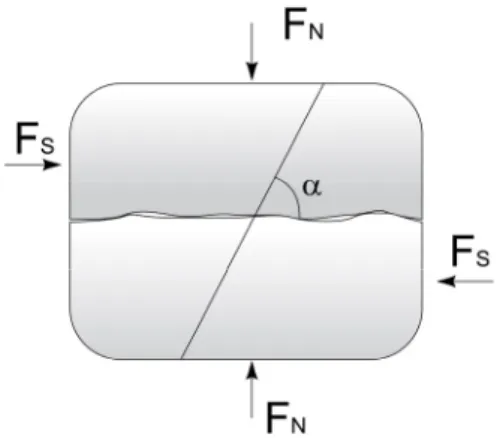
Fig. 1. Direct shear test of a bolted joint in a rock
Ludvig(1983) propose the equation for bolted joints overall shear resistance as the equation (1), and Gaziev and Lapin(1983) also suggest similar empirical equation based on regression analysis of the experimental results. Shear behavior of bolted joint surface are governed by several factors: cohesion, friction and dilation angle of joint surface, cross section area and material properties of bolt, and angle between rock bolt and joint surface.
(
φ α α)
τ
φ tan sin cos
tan + + +
+
= j n p b b b p
s cA F A T
F ( 1 )
Where Fs is shear force, Fn is normal force acting on surface, c is cohesion of joint, φp is friction angle of joint, Aj is the area of the joint, Ab is the area of the bolt, τb is the bolt shear failure stress, Tb is tensile force of rock bolt and α is inclination angle of the bolt.
First two terms of equation (1) are Coulomb-slip equation for the joint and last two terms are shear force of bolt and additional friction force due to tensile force of rock bolt. Therefore, rock bolt has the more area and tensile force; joint has the more overall shear strength. Besides, the equation (1) is also governed by inclination angle. By differentiation of equation (1) with respect to inclination α, optimum inclination angle can be found as the friction angle of joint surface. It means that bolts inclined at an angle less than 90 degree to the direction of shear movement have better reinforcing
properties that bolts installed more than 90 degree. It is because that if the bolts are inclined to the direction of shearing, compressive and shear stresses are generated in the bolt during the shearing, the reinforcing effect of the bolts becomes very small(Ludvig, 1983). Common practice of rock bolt installation is to put the rock bolt perpendicular to the joint because it is hard to predict the direction of shear movement in site, but if it is known then rock bolt is better to be installed inclined to the direction of shear movement.
For the effect of tensile force of rock bolt, McHugh (1999) suggests that axial loading has little effect on a joints resistance to shear loading from the test results. However, it is contrary to the other researchers who suggest that significant role of axial loading on the shear behavior (White, 2002).
3. Conditions of Numerical analysis 3.1 Modeling
The model for the shear test is regenerated, as the previous model of cylindrical shape model is not appropriate in applying the shear force on the curved surface. Also, previous model is generated by rotating single surface to make the flat bar into spiral, which result in not so good aspect ratio of elements.
Modeling of rock bolt and grout as a cylinder is easily done, but that of spiral bolt without rotating needs special care. To keep the model in good aspect ratio, no rotation for the grid points is used, but the edge is rotated with adjusting the nearest grid into edge and rest of the grid points are tranfinitely mapped. Rock bolt and spiral bolt is installed perpendicular to the joint for the simulation.
(a) Grid with joint interface (b) Spiral and Rock bolt Fig. 2. Representation of numerical test model
To model the joint, interface element of flac3D is placed in the middle of two separate upper and lower blocks. While test run for the interface, it is found that stress flows through interface is very
dependant to the ratio of normal stiffness of surface and elastic modulus of rock mass. If inappropriate parameters are chosen, the results could be unrealistic, so enough tests run should be performed before the main simulation.
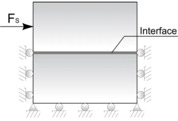
Bottom of Lower block is fixed in z-direction, left and right side is fixed in y-direction, and front and back side of Lower block is fixed in x-direction, where force is applied. Upper block is free to move for top, front and back side, except left and right as in figure 3.
Fig. 3. Boundary condition of shear simulation
The force is applied by applying constant velocity on boundary nodes for some steps to make a unit movement of upper block, then set the velocity zero and solve until internal unbalanced force is fully diffused to be in equilibrium by iteration. This process repeated for 30 times while measuring reaction force at the fixed boundary grid points. Graphs of force versus displacement can be obtained as the displacement was set and reaction force was measure at the moment.
Reaction force is actually unbalanced force at outer surface, boundary, so it can be measured by accumulating x-directional unbalanced force of wherever x-directionally fixed. But this does not work;
it is needed to accumulate x-directional unbalanced force of every nodes of lower block.
3.2 Properties
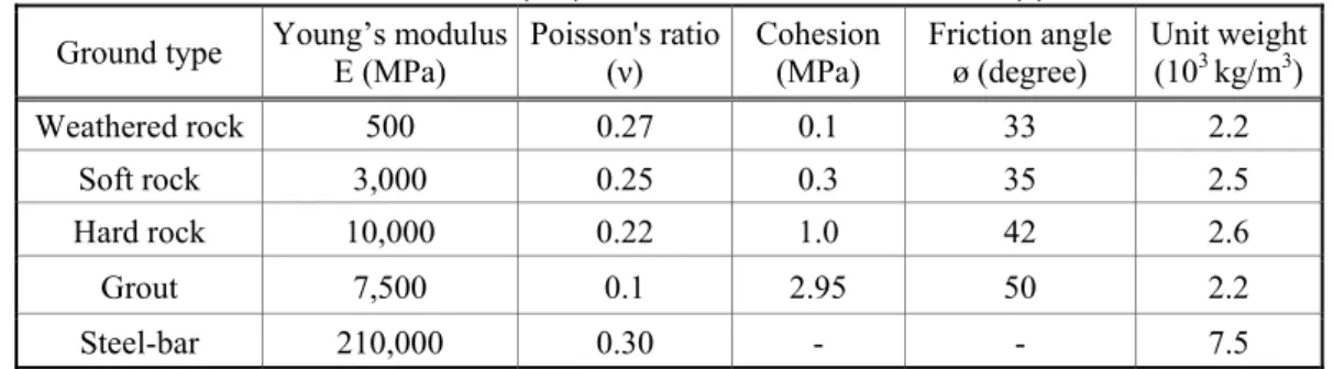
As the area of deformed bar for the rock bolt is larger that that of flat bar, so it is suspicious that support capacity of spiral bolt is lower than that of rock bolt. To investigate the effect of area difference on the equivalent stiffness of bolt embedded rock mass, simple shear simulation were done for bolt types: rock bolt and spiral bolt with 3 rock mass types. Table 1 shows the properties of various rock masses and supports and table 2 shows the properties of interface, which is sampled from geologic investigation report.
Table 1. Material properties of rock mass and support Ground type Young’s modulus
E (MPa) Poisson's ratio
(ν) Cohesion
(MPa) Friction angle
ø (degree) Unit weight (103 kg/m3)
Weathered rock 500 0.27 0.1 33 2.2
Soft rock 3,000 0.25 0.3 35 2.5
Hard rock 10,000 0.22 1.0 42 2.6
Grout 7,500 0.1 2.95 50 2.2
Steel-bar 210,000 0.30 - - 7.5
Table 2. Material properties of bolt embedded composite material type Normal stiffness
(MPa/m) Shear stiffness
(MPa/m) Cohesion
(MPa) Friction
(degree) Dilation
(degree) Slip
Interface 100,000.0 1.0 0.0 35.0 6.0 on
3.3 Cases of Simulation
Shear behavior of bolted joint is governed by rock mass and joint properties, bolt specification, tensile stress of bolt and inclination angle. From those factors, rock mass properties, tensile stress and bolt specification were chosen as parameters for the simulation.
For the different weathered condition, the capacity to grab the bolt can significantly influence the overall shear resistant behavior, as weathered rock will be yield before high tensile stress of rock bolt.
To investigate the effect of rock mass, simulations were done for 3 cases: hard rock, soft rock and weathered rock. One type of properties of joint is used for 3 cases of rock mass. It is obvious that joint properties are varied for different rock mass type. However, if different joint properties were used, then it is not clear to identify the effect of the other parameters.
If bolt has no pretension, then the major factor will be area and shape of bolt. While tunnel is constructed face by face, surrounding rock mass moves mostly toward inside of tunnel. It naturally causes tensile stress of installed rock bolt by resisting against the movement of rock. So, it is obvious to take into account the effect of axial load of rock bolt. What has to be figured out is that which effect is more dominant between sectional area and axial load in natural environment.
Two cases for axial loading were chosen; without axial load and with axial load. The method of axial load is done by simulating natural process happen in underground. First step is to pre-stress the rock mass, second step is to make a bore hole and install rock bolt and grout, third step is to release the stress of rock mass. First step represents residual rock load when the construction face is near, second step is obvious and third step represents tunnel face advanced far away, which result in tensile stress of rock bolt. Residual stress assumed to be 2MPa and the depth would be approximately 130m.
Two cases of bolt type were chosen; rock bolt and spiral bolt. Total 15 cases were analyzed for comprehensive comparison for the shear resistant behavior.
4. Results of Numerical Simulation 4.1 Shear behavior of Interface
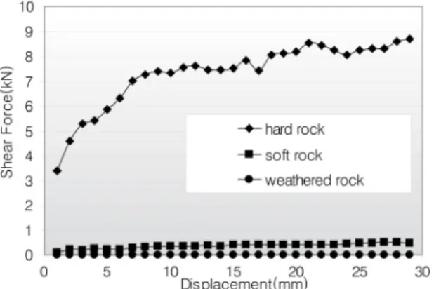
Shear resistant behavior for unbolted joints is shown in figure 4. As the properties of joint is the same for every case, significant difference of shear force between rock mass type shows that shear behavior is highly governed by underlying rock mass. Shear failure due to shear movement in joint surface cause dilation, and this in turn generate normal stress on surface. If underlying rock mass can bear the normal stress, then surface will maintain its shear resistant. Shear resistant for weathered rock mass is very low and almost negligible.
Fig. 4. Shear force versus shear displacement for rock mass type
4.2 Simulation of Shear on Bolted Interface
Figure 5 (a) shows the result for weathered rock mass that shear force for both rock bolt and spiral bolt with pretension is far greater than that without pretension. The shear force difference between with and without pretension for both rock bolt and spiral bolt is shown in figure 5 (b). The shear force differences remain within 20% range of its initial value. It means that initial axial loading is dominant factor for shear resistant for weathered rock mass. The performance of rock bolt is slightly better than that of spiral bolt for both with and without pretension.
The shear forces of spiral bolt for both with and without pretension show fluctuation from 10mm movement. Though the reason is not clearly identified, it is presumed because of numerical instability due to distorted shape of spiral bolt and low material properties of rock mass.
(a) Shear force verses shear displacement (b) Shear force difference between with and without pretention
Fig. 5. Results for weathered rock
Figure 6 (a) shows that the result for soft rock mass that shear force for both rock bolt and spiral bolt with pretension is still greater than that without pretension. However, the difference is less comparing to the figure 5 (a). The shear force difference between with and without pretension for both rock bolt and spiral bolt is shown in figure 6 (b). Unlike the figure 5 (b), the shear force difference of spiral bolt and rock bolt declined while that of spiral bolt remain higher than that of rock bolt. It means that initial axial loading effect of spiral bolt is more effective than that of rock bolt. The performance of rock bolt is slightly better than that of spiral bolt for without pretension. However, the performances of spiral bolt and rock bolt with pretension become equivalent. No fluctuations were found for shear forces of spiral bolt for both with and without pretension.
(a) Shear force verses shear displacement (b) Shear force difference between with and without pretention
Fig. 6. Results for soft rock
Figure 7 (a) shows that the result for hard rock mass that shear force for both rock bolt and spiral bolt with pretension is greater than that without pretension. However, the difference is less comparing to the figure 5 (a) and figure 6 (a). The shear force difference between with and without pretension for both rock bolt and spiral bolt is shown in figure 7 (b). The shear force difference of spiral bolt and rock
bolt declined while that of spiral bolt remain higher and stable than that of rock bolt. It means that initial axial loading effect of spiral bolt is more effective than that of rock bolt. The performance of rock bolt is slightly better than that of spiral bolt for without pretension. However, for the case of hard rock and with pretension, the performance is reversed: performance of spiral bolt is better than that of rock bolt with pretension.
(a) Shear force verses shear displacement (b) Shear force difference between with and without pretention
Fig. 7. Results forhard rock
5. Conclusion
Results from numerical shear simulation of different types of rock mass, different types of bolt and cases of axial loading can be summarized as follows.
(1) Shear resistant behavior of joint is significantly governed by rock mass properties, though the same properties of interface are applied.
(2) Initial axial loading is dominant factor for shear resistant for weathered rock mass. The performance of rock bolt is slightly better than that of spiral bolt for both with and without pretension.
(3) Initial axial loading effect of spiral bolt is more effective than that of rock bolt for soft rock mass.
The performance of rock bolt is slightly better than that of spiral bolt for without pretension. But, the performances of spiral bolt and rock bolt with pretension become equivalent.
(4) The performance of rock bolt is slightly better than that of spiral bolt for without pretension.
However, for the case of hard rock and with pretension, the performance is reversed: performance of spiral bolt is better than that of rock bolt with pretension.
(5) Comprehensive simulations for the comparison of shear performance between rock bolt and spiral bolt were performed. Shear resistant performance of spiral bolt for hard rock joint is slightly superior to the rock bolt, but shear resistant performance of rock bolt for soft rock and weathered joint is equivalent or slightly superior spiral bolt.
REFERENCE
1. Gaziev, E. G. and L. V. Lapin, 1983, Passive anchor reaction to shearing stress in a rock joint, In Proceedings of International Symposium on Rock Bolting, Abisko, pp. 101~108.
2. Hirata, A., S. Kokaji, S.S. Kang and G. Goto, 2005, Study on the estimation of the axial resistance of spiral bar based on interaction with ground, Journal of the Mining and Materials Processing Institute of Japan, MMIJ, Vol. 121, pp. 370-377.
3. Kang, S. S., A. Hirata and Y. Obara, 2005, A method for estimating of axial resistance of spiral bar developed as a new earth support system, Journal of Korean Society of Civil Engineers, Vol. 25, no. 6c, pp. 387~394.
4. Ludvig, B., 1983, Shear tests on rock bolts, In Proceedings of International Symposium on Rock Bolting, Abisko, pp. 113~123.
5. Li, C. and B. Stillborg, 1999, Analytical models for rock bolts, International Journal of Rock Mechanics and Mining Sciences, Vol. 36, pp. 1013~1029.
6. McHugh, E. and S. Signer, 1999, Roof Bolt Response to Shear Stress: Laboratory Analysis. In Proceedings of 18-th International Conference on Ground Control in Mining, Morgantown, WV, pp.
232-238.
7. Peng, S., Coal Mine Ground Control, John Wiley & Sons.
8. Signer, S., D. Cox and J. Johnston, 1997, A method for the selection of rock support based on bolt loading measurements, In Proceedings of 16-th International Conference on Ground Control in Mining, Morgantown, WV, pp. 183-190.
9. Song, M. K., S. Y. Choo, Kang. S. S. and Y. D. Cho, 2007, A Numerical Analysis for the Comparison of Support Behavior between Conventional Rock Bolt and Spiral Bolt, 89th Conference of Korean Society for Geosystem Engineering, Jeju, pp. 423-428.
10. White, B.G., 2002, Shear mechanism for mining induced fractures applied to rock mechanics of coal mines. In Proceedings of the 21st International Conference on Ground Control in Mining, Morgantown, WV, pp. 328-334.