초 록
EDISON CFD .
. ,
.
goe 417 (5 , 10 ) ,
(Wind-lens)
, . .
Key Words : (CFD), (Shrouded rotor), (Wind-lens), (Circulation),
(Pressure down), (Mass flow rate), (Wind turbine), (Vortex)
. P=ρAV3/2 A V
.
.
. (Shroud)
.
,
. Aniket C. Aranake [1], Sheila Wi
dnall [2], C J Lawn [3] .
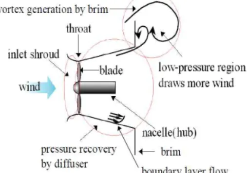
(Diffuser) (Brim)
.
Fig. 1 Airfoil circulation theory Fig. 2 Wind-lens theory
.
[4]
Wind-lens .
Shrouded rotor Wind-lens
EDISON CFD
. Wind-lens
(Diffuser) (Wind-lens)
. EDISON CFD
2 .
EDISON CFD
Wind-lens
.
.
goe 417 [5]
5 10
. 2
EDISON CFD “
2 SW (2D_I
ncomp_P)” . RANS
(Reynolds Averaged Navier-Stokes)
LU-SGS, Osher’s
upwind scheme . Menter’s k–ω
SST Viscous Adiabatic Wall,
Symmetry BC, Block Commun
ication, Far-Field BC .
Table 1 .
.
(1)
∞
(2)
⋅ ∞ (3) (mass flow rate) ,
(non-dimensional mass flow
amplification factor), (circulation) .
.
Fig. 5 .
.
. 1
1 . [5]
.
∼
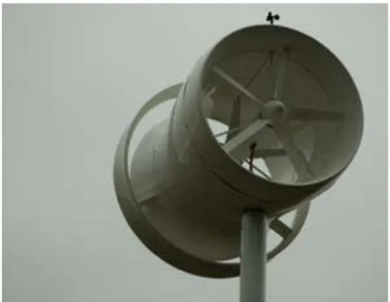
. [6] ∼
× Fig. 3 5kW Wind-lens turbines in a seashore
park in Fukuoka city, Japan
∞(m/s) Reynolds
Number (Re) Density (kg/m3) CFL Time-marching Convergence
Criteria
12 800,000 1.225 1.0 LU-SGS 10-4
Table 1 Flow condition
Fig. 4 Airfoil shrouded wind turbine
. 5
10 .
20 .
Wind-lens Fig. 8 .
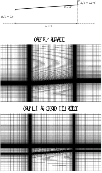
Long type L/D=1.25 . W
ind-lens h/L=0.075
. [7] 2.3.1
∼ . 4
10 Wind-le
ns 8 12
.
.
.
5 -6.3257 10 -9.0455
.
.
u, p streamline Fi
g. 13 . u
.
separation
Fig. 6 Grid system at .
Fig. 7 Grid system at Fig. 8 Wind-lens
Fig. 9 Grid system of Diffuser
Fig. 10 Grid system of Wind-lens
-3.2996
. 5
4
. goe 417
.
10% y
u Fig. 14 Fig. 15
.
sepa ration
. Table 2
Md Γ . Γ Md
.
. separation
(-) .
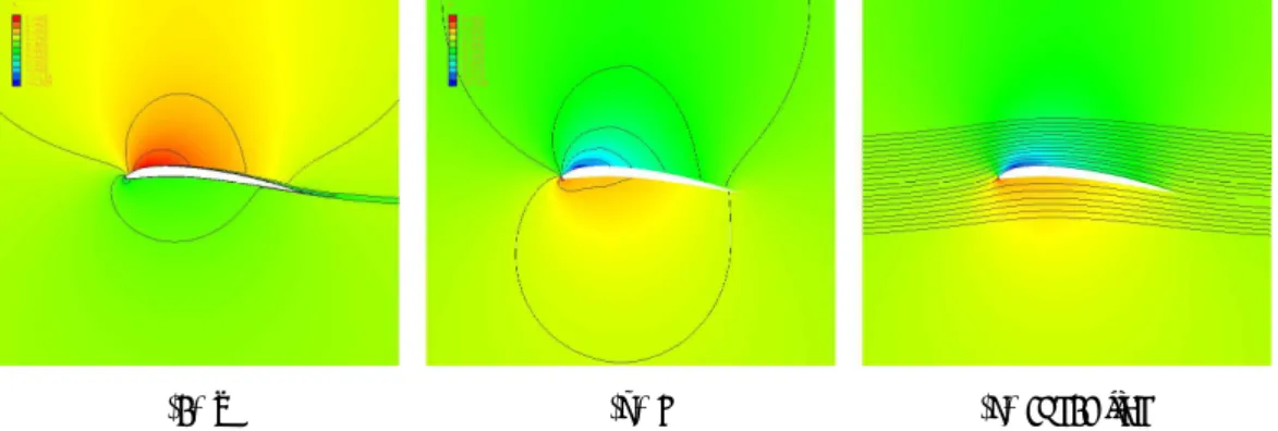
Wind-lens u, p, k streamline
Fig. 16 . u
. Wind-lens
separation Fig. 16 (a)
.
. Wind-lens inlet
. streamline
. Wind-lens (a) u (b) p (c) streamline
Fig. 11 Flow distribution around shroud at
(a) u (b) p (c) streamline Fig. 13 Flow distribution around diffuser
(a) u (b) p (c) streamline Fig. 12 Flow distribution around shroud at
0.0603 .
Wind-l ens
.
3.
, , Wind-lens
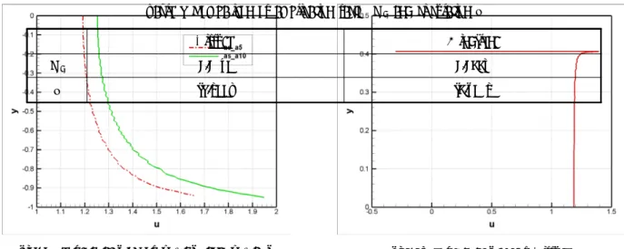
EDISON CFD . Fig. 14 y vs u at 0.1c of and
Shroud airfoil at Shroud airfoil at Diffuser
Md 1.2718 1.3730 1.1479
Γ -6.3257 -9.0455 -3.2996
Table 2 Comparison of amplication factor Md and circulation Γ
Fig. 15 y vs u at 0.1c of Diffuser
(a) u (b) p
(c) k (d) streamline
Fig. 16 Flow distribution around Wind-lens
Fig. 17 y vs u at 0.1c of Diffuser and Wind-lens
1. Γ
=-6.3257, Γ=-9.0455 7.76%
2.
3. .
.
4. 4 5
0.511
.
5. Wind-lens
2.51
3.54% .
separation .
0.0603 .
.
2015 ( )
(No. NRF-2011-0020557).
[1] Aniket C. Aranake, 2013, “Computational Analysis of Shrouded Wind Turbine Configurations”, 51st AIAA Aerospace Sciences Meeting including the New Horizons Forum and Aerospace Exposition, Vol.17, No.10, pp.1-4.
[2] Sheila Widnall, 2009, “Potential Flow Calculations of Axisymmetric Ducted Wind Turbines,”
[3] C J Lawn, 2002, “Optimization of the power output from ducted turbines,”
[4] Yuji OHYA, “The mechanism of acceleration of wind using a wind lens,”
[5] Aniket C. Aranake, 2013, “Computational Analysis of Shrouded Wind Turbine Configurations”, 51st AIAA Aerospace Sciences Meeting including the New Horizons Forum and Aerospace Exposition, Vol.17, No.10, pp.1-4.
[6] Salim M. SALIM, 2009, “Wall y+ approach for dealing with turbulent flow over a surface mounted cube: part 1-low reynolds number,” Seventh International Conference on CFD in the Minerals and Process Industries, Vol.7, No.2, pp.2-7 [7] S.A.H jafari, 2013, “Flow analysis of shrouded small wind
turbine with a simple frustum diffuser with computational fluid dynamics simulations,” Journal of Wind Engineering and Industrial Aerodynamics, Vol.102, No.15, pp.103-104