A Study on the Actuator for Robot Control Using Wireless ZigBee Sensor Networks
*Dae Seob Shin, *Hyeongcheol Lee
Abstract
The Interest in robotics has been steadily increasing in recent times both in Korea as well as abroad. Research on robots for new and diverse fields is ongoing . This study discusses the current research and development on robot actuator, which are used to control the joints of robots, and focuses on developing more efficient technology for joint control, as compared with the current technologies. It also aims to find means to apply the abovementioned technology to diverse industrial fields. We found that easy and effective control of actuators could be achieved by using ZigBee sensor networks, which were widely being used on wireless communications.
Throughout the experiments it is proved that the developed wireless actuator could be used for easy control of various robot joints. This technology can be effectively applied to develop two-legged robots that will be able to walk like human, or even quadruped and hexapod robots. It can also be applied to motors used in industry.
In this study, we develop an extremely minimized ZigBee sensor network module that can be used to control various servo motors with low power consumption even if it is long distances. We realized effective wireless control by optimizing the ZigBee antenna, and were able to quickly check the status of relevant Tree node through mutual communication between the servo motors composing the ZigBee sensor network and the main server control modules. The developed Servo Motor with ZigBee sensor network modules can be applied in both robotics as well as for home or factory automation.
Key words: Actuator, ZigBee Sensor Networks, Hexapod Robot, Two-legged Robot
*Department of Electrical Engineering , Hanyang University
Manuscript received May. 11, 2011 ; Revised Aug. 22, 2011 Accepted Sep. 01 2011
I. Introduction
Robots are expected to be widely used in various industrial fields in the future. One of the requisites for this to occur is the development of robots having multiple joints, and correspondingly diverse shapes. These multiple joints are controlled using DC servo motors, which in turn are controlled by signals sent from a central processing unit. For example, servo motors used to perform a walking operation of multiple joint robots are controlled using parallel ports or by I2C, SPI, or RS232, IP Network communications[3][4][5][6].
However, it is difficult to remotely control joints using the abovementioned method because of the large distance between the CPU and the servo motors. Further, the noise generated by the
movement of the joints disturbs the communications between the CPU and the actuators. Another disadvantage of this approach is that the control unit is located far away from the operating part , and thus, it becomes impractical to check the status of actuators from the control unit. To resolve these problems, in this study, we tried to find ways to develop a ZigBee sensor network to enable efficient and effective communications between the CPU and the actuators. We constructed ZigBee stacks to perform instantaneous fault tolerance by checking for faults generated in each actuator and communicating this information to the main system.
Position control of the motors (robot position control) was achieved through the design of a reducer and by installing rotary sensors on the output axis , using a proportional–integral–
derivative controller for servo motor control, and by developing a motor to connect the developed ZigBee sensor network module to the control unit of the servo motors. Our design is such that the temperature and status of the servo motors can be transmitted to the main control system. Each motor has its own ID and can connect to the ZigBee
sensor network using the power applied to the actuators ; it can transmit information independent of other motors or receive information on status of the main system and the position control.
Fig. 1. Structure of DC motor
This paper does not analyze the description about the operation of robots and the motors. Instead, it will describe the inside structure and control methods of a ZigBee wireless digital actuator, antenna matching, and a strong point of wireless that were studied to develop the ZigBee sensor network wireless board used for wireless control.
This paper will also discuss how the servo motor control system is interfaced with external devices.
II. Design and Developmnet
We developed a ZigBee sensor network module, and then, used it to develop an actuator ; this paper explains the development of both. We performed experiments using hexapod robots to test the utility of the developed actuator.
2.1 ZigBee Sensor Network Module Development The ZigBee Sensor Network Modules was designed and constructed to perform wireless control of the digital actuator that will be used for the robot joints. The module included an MG2400, ZigBee wireless chip, equipped with 8051 core, which was minimized as much as possible to be installed inside a small-sized digital servo motor.
Further, this system is equipped with a chip antenna that can be remote controlled from up to 50m, and it is designed so as to change the IDs to control 255 servo motors in a given area. It can also change the ZigBee wireless channels to control a total of 16 channels as a group in a given area.
The system is equipped with an IC for USB
functionality, and therefore, a user can set the functions of the ZigBee sensor network module via the USB port of a PC. We designed the wireless part of the MG2400 in advance to perform wireless control and antenna matching using the ALA921C5, chip antenna.
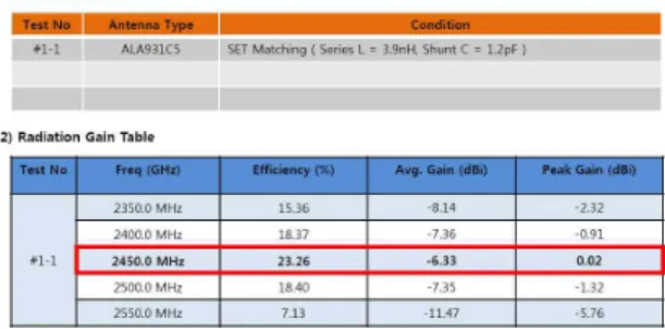
ZigBee Antenna Design - ALA931C5
- L, C values set for antenna matching
- The following experiments were performed to measure radiation gain
Table 1. Efficiency at 2450Mhz
The highest efficiency of 23.26% was realized for 2450 Mhz, -6.33 avg. gain, and 0.02 peak gain.
Figure 2 shows an image of the ZigBee sensor network and the constructed L and C values used to perform the antenna matching for measuring the S-parameters and radiation gain.
Fig.3 shows the measured S-paramters which means the ratio between input voltage and output voltage in a given circuit system. S11 is the only output value because there are normally input ports in Antenna except for multi-ports.
According to the graph, S11 illustrates the downward slop that means input voltage doesn't reflect and is emitted to the outer space the most.
It means that the reflection characteristic is good when S11 and SWR decrease together. On this graph, the center frequency for matching is 2.45GH and the experiment result of it is 2.427GH.
We got the load impedance by ploting S11, the reflection coefficient, on the Smith Chart(under part of Fig.3) and L, C values are determined through it. The Smith Chart shows that points 1~4 tend to be inner circle because S11 is very low(it also means little reflection). The left and right part of
points 1~4 are spreading to the outer circle because S11 is very high.(it also means a lot of reflection) 1) Antenna Layout and Measurement of S-parameters
[Fig.2] Antenna layout and matching values
[Fig.3 ] Measured S-parameters
2) Radiation Gain
Radiation gain values were measured to check the antenna matching efficiency using the method of 3 dimensions, X, Y, and Z.
[Fig.4] Radiation gain in X,Y, and Z directions
[Fig.5] The axis of coordinates for Radiation gain in X,Y, and Z direction
Antenna usually has its own beam pattern characteristic which means the directivity of antenna for a specific direction and location. You can see the beam pattern figure through Fig.4, Fig.5, and Fig6.
The physical meaning of these beam patterns is to show the electric field strength of the radiated electromagnetic in all directions. Antenna gain is a relative gain derived from the directivity that tells us the ratio of some energy concentrated on a one direction. The dimension is dBi, as for the isotropic antenna.
[Fig.6] Measured radiation gain at all angles.
The larger the antenna gain is, the sharper the output signal concentrates on a one direction.
In this antenna, I took the low gain but wide beam width to get the antenna matching for all direction properly and Fig.6 illustrates them.
Once antenna matching is achieved by measuring the radiation gain, it is easy to construct and control the wireless network from a long distance using the main system.
2.2 Development of ZigBee Wireless Digital Actuator The actuator was developed by using the ZigBee sensor network wireless module previously developed. The revolving direction and position of the actuator were controlled by installing a DC motor, metal speed reducer, and rotary sensor inside the actuator. Further, the system was designed to be controlled remotely and wirelessly by connecting the ZigBee wireless module to the control unit inside the actuator. Moreover, the system could be controlled by constructing ZigBee Stack and the networks between the actuator and main control system to perform the sensor network in the ZigBee wireless module.
2.3 Structure of the Applied ZigBee Stack
The ZigBee stack is constructed to port the ZigBee stack software of the sensor network to the developed ZigBee sensor network module, so as to control it using the network. Fig.7 shows the basic structure of the ZigBee stack.
[Fig.7] Structure of ZigBee stack
[Fig.8] ZigBee stack software diagram
[Fig.9] Appearance of ZigBee sensor network module
[Fig.10] Developed ZigBee sensor network board Fig.8 shows the structure of the software used in the experiment. This was adopted from the basic structure provided by the ZigBee Alliance. It consists of an interface part for communications with APP to control the IEEE of the PHY layer, a MAC layer, a data -link layer, and a network layer.
The structure also includes APSDE and APSME at the APS and APP parts , and controls the PID of the application part to control the servo motor.
2.4 Structure of Digital Servo Motor
We developed the digital servo motor by using the developed ZigBee sensor network module. Figure 11 shows the appearance, internal structure, and block diagram of the developed servo motor. The digital servo motor is composed of a motor drive, rotary sensor for position control, and metal gear that act as a reducer.
[Fig.11] Digital servo motor
Fig.12 shows the inside block diagram of the developed wireless servo motor.
It has the RS232 communication between Zigbee wireless module and ATmega48V CPU. It is also designed to enable motors to do the PID location control by using the Rotory Sensor in it and have the specific motor driver IC(IRF7389) for operating DC motors.
Besides, it includes the voltage and current detection to make a stable control. Fig.13 shows the structure of designed control board installed in the digital servo motor.
It allows us to change the channel options and ID
of the wireless module in PC if USB port is embedded in it. We are able to interface it through USB driver IC(CP2102).
[Fig.12] Block diagram of the working of a wireless digital servo motor
[Fig.13] Internal configuration of the digital servo motor
III. Experiment
The digital sensor network module installed in the developed wireless actuator consists of the MG2400 with an 8051 core; it was constructed to install EEPROM externally. It is developed based on the C language with a Keil C compiler. Further, to minimize its size, the PCB was designed in multi-layer (6 layers). We constructed a hexapod multi-joint robot system to evaluate the efficiency of the digital servo motor with the wireless module,
and to verify whether the developed digital servo motor was more effective than existing servo motors, for this walking tests were performed. We constructed each servo motor to be set by a packet [Table. 2] ; it was necessary to set the channel and ID for each motor individually. The channel and ID of each actuator could be set by connecting the actuator to USB ; then, the Windows terminal program and other communication programs were used.
[Table 2] Setting Packet Format
S1234 FFFF FF 0B 0015510000 01 00 02
Fan_ID Short
Addr REV RF Ch Set Value RX/TX Sub_ID ID
[Fig.14 ] Multi-joint hexapod robot
We constructed a multi-joint hexapod robot and installed the developed actuator in it. The figure shows the developed multi-joint hexapod robot equipped with 18 actuators. Three actuators were applied to each leg, and the robot had six legs.
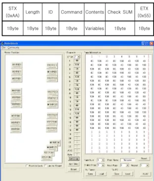
Figure 16 shows the remote control teaching program developed to control the robot. We set the values for controlling the robot, and these values were transmitted to the control board of robot by wireless control. Table 3 shows the structure of the data packet used for controlling each wireless actuator. It consists of a total of 7 byte frames, and is transmitted to each ID and servo motor control value wirelessly. The status values of the actuator were successfully read, and the control performance was good.
[Table 3] Serial Data Packet Format
STX
(0xAA) Length ID Command Contents Check SUM ETX (0x55) 1Byte 1Byte 1Byte 1Byte Variables 1Byte 1Byte
[Fig.15]Robot Control Software
IV. Conclusions and Future Research In this study, we designed and constructed wireless actuators by applying ZigBee sensor network technology. These actuators were installed
in a multi-joint robot, and their efficiency for control was evaluated. Further, we connected the motors to the network using the method of Star network of the ZigBee sensor network, and performed antenna matching to increase the wireless sensitivity of the network. We examined the connections between the digital actuators and the network by using the structure of stack of the ZigBee sensor network to the developed ZigBee wireless module, and tries to find the best method for controlling the actuator (node). We were able to easily and remotely control the robot using the control unit, and we developed a remote control teaching program to enable the robot to walk effectively ; this was achieved by using the values of the teaching program to simulate robot motion on the PC . In this system, we have managed to remove the inconvenience caused by the noise of signal and expansion of line that currently plague existing controls for multi-joint robots. We performed experiments the to develop a method to control the robot joints by applying the power to the joints and transmitting/receiving control values wirelessly. We believe that the achievements of this study will lead to the development of easy and efficient control for robot joint.
References [1] Http://www.zigbee.org.
[2] IEEE Standard 802, part 15.4 : Wireless Medium Access Control(MAC) and Physical Layer (PHY) Specifications for Low Rate Wireless Personal Area Networks (LR-WPANs), 2003.
[3] Ki-Won Song, Gi-Sang Choi, Gi-Heung Choi. "
Tracking Position Control of DC Servo Motor in LonWorks/IP Network" Int Journal of Control, Automation, and System, vol. 6, no. 2, pp.186-193, April 2008.
[4] Guomin Li and Kai Ming Tsang. "concurrent Relay-PID Control for Motor Position Servo Systems"
Int Journal for control, Automation, and Systems, vol.
5, no. 3, pp.234-242, June 2007.
[5] CARBONE G and YATSUN A. " Design and Simulation of Cassino Hexapod Robot" Proceedings of the 13th WSEAS International Conference on
SYSTEMS July 22-24, 2009
[6]Rebula, J.R., Neuhaus, P.D., Bonnlander, B.V., Johnson, M. J., Pratt, J.E. (2007) A controller for the littledog quadruped walking on rough terrain. In Proc. IEEE Int. Conf. on Robotics and Automation, pages 1467-1473, Roma, Italy.
[7]Walas, K., Belter, D., Kasinski, A.(2008) Control and environment sensing system for a six-legged robot. Journal of Automation, Mobile Robotics and Intelligent Systems, 2(3):26-31.
BIOGRAPHY
SHIN DAE SEOB (Student Member)
1996: BS degree in Electronics Engineering ,Howon University.
1998: MS degree in Electronics Engineering , Inha University.
Present: Ph. D. Course in Electrical Engineering, Hanyang University
<Research Interests > Image processing, neural network, Adaptive control , Signal Processing, Embedded Control, Rehabilitation robots
Hyeongcheol Lee (Non Member)
1988: BS degree in Seoul National University.
1990: MS degree in Seoul National University.
Present: a Professor in Division of Electrical and Biomedical Engineering, Hanyang University
<Research interests> Adaptive and nonlinear control, embedded systems, and applications to robotics and vehicle controls