Spray Characteristics of the Rocket Oxidizer-rich Preburner Injection System
Joon-Ho Yang*, Seong-Man Choi*, Young-Min Han**
Department of Aerospace Engineering, Chonbuk National University, Jeonju, 561-756, Korea
[email protected]**Korea Aerospace Research Institute, Korea
Keywords: Oxidizer-rich preburner, Liquid-liquid coaxial swirl injector, Spray characteristics, Spray angle, High ambient pressure, PDPA, SMD
Abstract
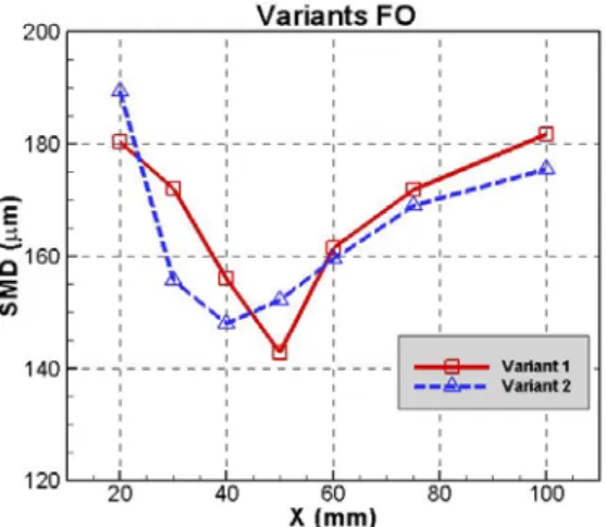
This paper presents the spray characteristics of the oxidizer rich preburner injector which can be used in the high-thrust rocket system. We designed the basic shape of the liquid-liquid coaxial swirl injector for the rocket oxidizer rich preburner injection system. To understand the spray angle variation with the high pressure environment, the spray visualization in the high pressure chamber was preformed. Also we measured the droplet velocity, the Sauter Mean Diameter (SMD), the volume flux and the number density with the PDPA system by using water in atmospheric pressure. The results show that the spray angle is reduced by increasing ambient pressure and maximum droplet velocity is shown from a nozzle tip and then the droplet velocity decreases as a spray moves to the downstream. The SMD decreases on the axial distance from 20 mm to 50 mm but it increases over 50 mm. That is due to the increasing number of collision with each droplet and interaction with ambient air on going downstream direction.
NOMENCLATURE
PDPA : Phase Doppler Particle Analyzer ORPB : Oxidizer-rich Preburner
o
D F : Fuel Orifice Diameter [mm]
o
D O : Oxidizer Orifice Diameter [mm]
n
D F : Fuel Nozzle Diameter [mm]
n
D O : Oxidizer Nozzle Diameter [mm]
Δ P : Pressure Drop [kgf/cm2]
F25O10 : Fuel 25 kgf/cm2, Oxidizer 10 kgf/cm2 SMD : Sauter Mean Diameter [μm]
1. INTRODUCTION
Korea succeeded in launching the liquid propellant rocket KSR-III in 2002 and has a plan to launch the 100kg-level small-sized satellite launch vehicle KSLV-I and the 1,500kg-level practical satellite launch vehicle KSLV-II by 2017. Furthermore, the launch vehicle that will be launched in the future requires a high-performance and a high-thrust.
Therefore, it is necessary to develop the closed cycle engine using the oxidizer rich preburner which has higher efficiency than the open cycle engine [1].
However, it is known that the process pursuing a high- efficiency in the liquid rocket engine system incurs a combustion instability phenomenon. Therefore, it is essential to develop a stable high-efficiency propellant injection system [2].
In order to understand oxidizer rich preburner injection system, we designed the basic shape of the liquid-liquid coaxial swirl injector for the oxidizer rich preburner injection system and measured the droplet velocity, the SMD, the volume flux and the number density with the PDPA system by using water in ambient environment. To understand the spray angle variation with the high pressure environment, the spray visualization in the high pressure chamber was preformed.
2. OXIDIZER RICH PREBURNER INJECTOR The RD-170 made by Russia is the most typical launch vehicle using the oxidizer rich preburner [3].
The RD-170 has the highest thrust 7904 kN in vacuum in the world and has two preburners [4].
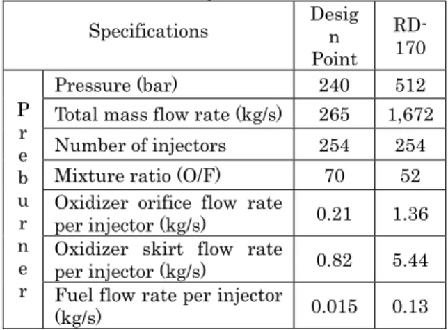
Approximately 10% thrust level of RD-170 is used as design point of this study. From the basis of the RD- 170 operating conditions and design specifications, we determined the mixture ratio of oxidizer & fuel, the pressure drop of our system. From this design point, we determined fuel & oxidizer orifice diameters, nozzle diameters and other injector specifications which are shown in Table 1.
Table 1. Design specifications of the ORPB injector
Specifications Desig n Point
RD- 170
P r e b u r n e r
Pressure (bar) 240 512
Total mass flow rate (kg/s) 265 1,672
Number of injectors 254 254
Mixture ratio (O/F) 70 52 Oxidizer orifice flow rate
per injector (kg/s) 0.21 1.36 Oxidizer skirt flow rate
per injector (kg/s) 0.82 5.44 Fuel flow rate per injector
(kg/s) 0.015 0.13
3. EXPERIMENTAL APPARATUS
3.1 Injector
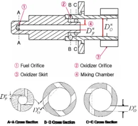
In order to observe spray characteristics, the liquid- liquid coaxial swirl injector is designed and manufactured which is shown in Fig. 1 [5]. Two injectors are produced. The key factors of injector specifications are shown in Table 2. Fuel is provided by four fuel orifices(➀), 20% of oxidizer is provided by eight oxidizer orifices(➁) and 80% of oxidizer is provided by eight oxidizer skirts(➂). In the mixing chamber(➃), 100% fuel and 20% oxidizer are mixed and occur the combustion. The 80% oxidizer for skirt flow cools the combustion gas from the mixing chamber. The swirl direction of the fuel & oxidizer is clockwise.
3.2 High pressure chamber system
The high pressure chamber system was introduced to understand effect of ambient air pressure to the spray characteristics. The high pressure chamber system composed of the main chamber, fuel supply tank, gas supply tank and controller. The diameter of main chamber is 500 mm and volume is 200 L. The maximum chamber pressure is 120 kgf/cm
2. For the safety of the experiment, we used below 20 kgf/cm
2. The cover of main chamber can be rotated for moving spray injector during test. We used water as test fluid.
Water is supplied of pressure difference between providing pressure and ambient pressure. This is controlled by the controller. After injection to the chamber, chamber pressure is increased by the water.
This increasing pressure should be ejected to the outside. This process is conducted automatically by sensing the chamber pressure. In addition, water supply tank pressure is decreased due to the increasing gas volume. This is also controlled automatically by exhaust valve operation. Gas curtain system is used for the clean access of the CCD camera.
Fig. 2. Experimental apparatus of PDPA
3.3 PDPA system
In order to measure the droplet velocity, the SMD, the volume flux and the number density with the PDPA system, experimental apparatuses are shown in Fig. 2. They are composed of the water pump, the PDPA system, the traversing system and the data processor.
The pressures of the fuel & oxidizer are measured with the pressure sensor(Sensys) and the computer software(LabVIEW). The PDPA system consists of an optical system, a signal processing system and a three- dimensional traversing system. The water-cooled Ar- ion laser is used for light source and the optical system is composed of the transmitting and receiving optics.
The transmitting optics makes a laser beam cross at the measuring point. The receiving optics detects the scattered light, which is produced when droplets pass through the measuring volume, and then transmit it to the signal processor. The signal processor (DANTEC, 58N10) is a burst detector type, so that the velocity and size are measured by the frequency and relative phase difference of the Doppler signal, respectively.
4. EXPERIMENTAL CONDITIONS
4.1 High pressure chamber system
Variant 1 was conducted to study spray visualizations with changing ambient air pressure as illustrated in Table 3. CCD camera(KODAK ES1.0 1008×1008) was set up to taken spray photography with exposure time 1/10s, F number 11 and ISO 200.
Frequency of stroboscope was maintained at 10 Hz and stroboscope was shed through semitransparent paper. The instantaneous images were taken by
Fig. 1. Schematic of the injector Table 2. Design parameters of ORPB injectors
Variant 1 2
o
DF
(mm) 0.6 0.7
o
DO
(mm) 1.2 1.2
n
DF
(mm) 1.67
n
DO
(mm) 5.5
No. of Fuel Orifice 4
No. of Oxidizer Orifice 8
shedding the light just one time for exposure time without synchronizing with CCD camera. Spray angle was determined by averaging 60 instantaneous images.
Table 3. High pressure chamber test conditions
unit : kgf/cm2 Ambient air pressure Injection pressureFuel Oxidizer Combine 0, 5, 10, 20, 30 25 10 Fuel 25
Oxidizer 10
4.2 PDPA system
We measured under the 10,000 sampling data at each measuring point and maximum measuring time is 20 seconds. The focus length of the receiving optics was set at 400 mm and the focus length of the transmitting optics was set at 500 mm. The scattering angle of the transmitting optics was set at 40° and the angle adjustment was set at 0.2 mm. The bandwidth of the Doppler frequency, which determined the measurement range of velocities, was set at 12.00 MHz. Also, the laser power was set at 600 mW and the high voltage was set at 1000V on U1, 1100V on U2 and 1200V on U3.
5. EXPERIMENTAL RESULTS
5. 1 Spray visualizations
Fig. 3 shows photographs of fuel spray and Fig.4 shows spray angle with ambient air pressure. The spray angles are reduced with ambient pressure except F5 case. The case of fuel supplying pressure of 5 kgf/cm
2(F5), spray is not fully developed at atmospheric condition which is shown at Fig. 3. In the F15 and F25 case, spray angle contraction is proceeded up to 5 kgf/cm
2. But over than 5 kgf/cm
2, spray angle contraction is virtually ceased.
Fig. 5 shows photographs of oxidizer spray with increasing ambient air pressure. Fig. 6 shows oxidizer spray angle with ambient air pressure. The oxidizer spray angle was reduced by increasing ambient air pressure from 82° to 65° and sheet disintegration starts to occur close to the nozzle discharge orifice.
Increasing ambient air pressure caused the spray to become more mono disperse.
Fig. 7 shows photographs of combined spray with increasing ambient air pressure. Fig. 8 shows combined spray angle with ambient air pressure. The combined spray angle was reduced from 77° to 53° by increasing ambient air pressure. In that case, the spray angle was reduced more than oxidizer only. It seems that oxidizer swirl velocity was decreased by collision of fuel and oxidizer droplets. From the visualization, increasing ambient air pressure makes spray angle narrow.
unit: kgf/cm2
Fig. 3. Photographs of fuel spray with increasing ambient air pressure
Fig. 4. Fuel spray angles with ambient air pressure
unit: kgf/cm2Fig. 5. Photographs of oxidizer spray with increasing ambient air pressure
60 65 70 75 80 85
0 5 10 15 20 25
Ambient air pressure(kgf/cm2)
Spray angle(°) O5
O7.5
O10
Fig. 6. Oxidizer spray angles with ambient air pressure
0 5 10 15 20 25 30
0 5 10 15 20 25
Ambient air pressure(kgf/cm2)
Spray angle(°) F5
F15
F25
5. 2 Spray characteristics of PDPA
Combined spray characteristic result of Variant 1 is shown in Fig. 9. When performing PDPA experiment, we measured 20, 30, 40, 50, 60, 75 and 100 mm in the axial direction(X axis) from a nozzle tip and measured radial direction(Y axis) from each X axis.
Fig. 9(a) is the result of the SMD measurement. The SMD decreases on the axial distance from 20 mm to 50 mm but it increases over 50 mm. It was found that the droplet breakup occurs at the position around 50 mm from a nozzle tip. This is explained by the number density of Fig. 9(b). The definition of the number density is a droplet number atomized in measuring unit volume. When many large-sized droplets are distributed in measuring unit volume, the number density gets low value. When many small-sized droplets are distributed in measuring unit volume, the number density gets high value. The case of the axial distance 50 mm, the number density is highest value and peak SMD is smallest among the axial distance cases. So we could understand the relationship between SMD and number density.
Fig. 9(c) is the U velocity of axial direction(X axis).
As shown in graph, the velocity is highest as 26 m/s in 20 mm from a nozzle tip and the velocity decreases as a spray moves to the downstream. It is explained that as a spray moves to the downstream, the sprayed area
unit: kgf/cm2Fig. 7. Photographs of Combined spray with increasing ambient air pressure
Fig. 8. Combined spray angle with ambient air pressure
(a) SMD (b) Number Density
(c) U Velocity (d) Volume Flux
Fig. 9. Spray characteristics of Variant 1 at F25O10
50 55 60 65 70 75 80
0 5 10 15 20 25
Ambient air pressure(kgf/cm2)
Spray angle(°)
F15 O10
F20 O10
F25 O10