• 검색 결과가 없습니다.

Combining an Edge-Based Method and a Direct Method for Robust 3D Object Tracking

N/A
N/A
Protected

Academic year: 2021

Share "Combining an Edge-Based Method and a Direct Method for Robust 3D Object Tracking"

Copied!
11
0
0

로드 중.... (전체 텍스트 보기)

전체 글

(1)

1. INTRODUCTION

Augmented reality (AR) has shown promising applications for education, industrial training, and even recreational purposes. For AR, the 3D camera (or object) pose has to be estimated using visual information from the camera images. In the liter- ature, there are two main approaches for camera pose estimation: marker-based[1,2] and markerless [3,4]. Marker-based methods use fiducial markers that usually have primitive shapes and discrim- inative colors, thus are easy-to-implement and robust. However, placing markers in the user space is visually disturbing, which makes users unpleasant. Also, marker-based methods are in- herently vulnerable to occlusion. Therefore, they

have become less attractive with time. Therefore, markerless methods use image features (such as corners or blobs) and their geometry instead of markers, to overcome the problems of marker- based methods. However, they require the target scene (or object) be rigid and of rich texture, and they are less reliable than marker-based methods.

Model-based methods[5,6,7] also do not require markers, so they can be considered as a kind of markerless methods. However, as model-based methods use 3D knowledge of the target scene (or object), i.e., 3D scene/object model, they are highly reliable and computationally efficient.

Model-based methods estimate the camera pose from 3D-2D correspondences between the 3D model data and its corresponding 2D observations

Combining an Edge-Based Method and a Direct Method for Robust 3D Object Tracking

Jean-Pierre Lomaliza

, Hanhoon Park

††

ABSTRACT

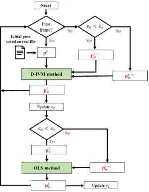
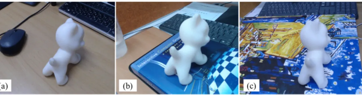
In the field of augmented reality, edge-based methods have been popularly used in tracking textureless 3D objects. However, edge-based methods are inherently vulnerable to cluttered backgrounds. Another way to track textureless or poorly-textured 3D objects is to directly align image intensity of 3D object between consecutive frames. Although the direct methods enable more reliable and stable tracking compared to using local features such as edges, they are more sensitive to occlusion and less accurate than the edge-based methods. Therefore, we propose a method that combines an edge-based method and a direct method to leverage the advantages from each approach. Experimental results show that the proposed method is much robust to both fast camera (or object) movements and occlusion while still working in real time at a frame rate of 18 Hz. The tracking success rate and tracking accuracy were improved by up to 84% and 1.4 pixels, respectively, compared to using the edge-based method or the direct method solely.

Key words: 3D Object Tracking, Camera Pose Estimation, Edge-Based Method, Direct Method, Textureless Object, Augmented Reality

※ Corresponding Author : Hanhoon Park, Address: (608- 737) Yongso-ro 45, Nam-gu, Busan, Korea, TEL : +82- 51-629-6225, FAX : +82-51-629-6210, E-mail : hanhoon.

[email protected]

Receipt date : Jan. 4, 2021, Revision date : Jan. 8, 2021 Approval date : Jan. 12, 2021

††

Dept. of Electronic Engineering, Pukyong National University (E-mail : [email protected])

††

Dept. of Electronic Engineering, Pukyong National University

※ This work was supported by the Pukyong National

University Research Fund in 2019

(2)

in the camera image. As each correspondence in- dependently contributes to the camera pose esti- mation, model-based methods with robust estima- tors can be robust to occlusion. The workflow of a model-based method is shown in Fig. 1. Printed models that have dense textures are advantageous since the 3D-2D correspondences are directly es- tablished by either feature point matching[8,9] or template matching[10,11]. On the other hand, when the target 3D object is textureless or poorly-tex- tured, edges are the only information to rely on.

In such edge-based methods, the 3D object’s mesh data is projected on the camera image and matched with its corresponding 2D image edges detected via local search in the normal direction of projected object boundary. Then, the 3D camera (or object) pose between consecutive frames are recovered from 2D displacements between the corre- spondences. Since the initial edge-based method, RAPID tracker[5], was proposed, a number of var- iants with different computational frameworks have been reported and their performance has been con- siderably improved[6,7]. However, edge-based

methods have suffered from matching errors com- monly caused by clutters on either the object’s sur- face or background. Therefore, the optimal local searching (OLS) method[12] introduced a robust way to find the correspondences in heavily clut- tered backgrounds.

As another attractive approach for tracking tex- tureless or poorly-textured 3D objects, direct me- thods[13,14,15] are inherently less influenced by the object or background clutters because they ex- ploit rich information in an image to estimate the camera pose instead of relying on local features such as edges. In direct methods, brightness (in- tensity) constancy between consecutive frames is commonly assumed. However, the assumption is violated due to intensity variations, which are usu- ally caused by illumination changes. To tackle this problem, a direct method[16], called D-IVM (Direct method with an Intensity Variation Model) here- after, introduced an approach that models intensity variations using the surface normal of the object under the Lambertian assumption.

Each of the OLS and the D-IVM methods tack- les limitations on its respective tracking approac- hes. However, we observed that the local search nature of the OLS method exposed the weakness to fast camera (or object) movements that make a large distance between the correspondences and weaken edge strength, especially with cluttered backgrounds; the nature of using the information on the entire object region of the D-IVM method exposed the weakness to occlusion and the in- accuracy in object boundary matching. Therefore, based on the fact that the weakness of one method can be compensated by the other, we introduce an approach that smartly combines the OLS and D-IVM methods to create a system that is con- sistent and accurate in tracking and robust to occlusion. The main contribution of this paper is the design of a method that combines the two dif- ferent types of tracking approaches to exploit their respective strengths and tackle their respective Fig. 1. Overall working flow of model-based 3D object

tracking. (a) Camera image containing the tar- get 3D object. (b) Mesh model of the 3D object.

(c) Contour (in green) of the 3D mesh model

projected on the image using the initial (or pre-

vious) camera pose. (d) Drawn 3D mesh model

(in red) after refining the camera pose from the

displacement between the contour and its cor-

responding image edges.

(3)

weaknesses.

2. TWO BASE METHODS

In this section, we describe two types of model- based 3D object tracking methods that we used to combine in the proposed method. The first method is the OLS method[12] which is an edge-based method, and the second method is the D-IVM method[16] which is a direct method.

2.1 OLS Method

Given a 3D mesh model of the target object M, an initial camera pose E

0

, and camera images ob- tained using a calibrated RGB camera, edge-based 3D object tracking methods estimate the current camera pose E

t

at time t by updating the camera pose of the previous frame E

t-1

with infinitesimal camera motions between consecutive frames Δ, so that E

t

= E

t-1

Δ . The infinitesimal camera motions are computed by iteratively minimizing the dis- tances (dist

i

) between the projections of boundary points (M

i

) sampled on the 3D mesh model with E

t-1

and their corresponding 2D image edges m

i

as follows:

(1)

Here, φ(·) is a robust estimator to penalize outliers, K is the camera intrinsic matrix, and N is the num- ber of boundary points. With this formulation, the OLS method proposed a robust way to finding cor- responding image edges in cluttered backgrounds.

The OLS method defined regions of the image

as Φ

{+,0,-}

representing three levels with Φ

+

being

the interior region, Φ

0

being the contour, and Φ

-

being the exterior region, based on the projected contour of 3D object mesh model. The projected contour is sampled into s

i

. From each sample s

i

, corresponding edge candidates c

i

are searched on the image toward normal directions along 1D searching line noted as l

i{+,0,-}

within a certain range

|η|. Based on three levels of regions, matching can-

didates c

i{+,0,-}

are pixels with local maximum gra- dient responses (computed using a filter mask [-1 0 1]) above a certain threshold ε. Then, the true correspondences c

i*

will exist among the candi- dates c

i{+,0,-}

. However, the OLS method searches for matching candidates in only confident direc- tions. Specifically, the method prioritizes searching for potential matches towards interior regions through 1D line l

i{+,0}

. Only when there is no match in the interior region, the method searches for matches towards exterior regions.

Besides the prioritized searching scheme, the OLS method modeled the local appearance of object surface region and background region using a his- togram-based representation in the hue-satu- ration-value (HSV) color space to keep it less sen- sitive to illumination. The appearance model is then used to suppress the false edges caused by object or background clutters.

2.2 D-IVM Method

Given a 3D mesh model of the target object M, an initial camera pose E

0

, and camera images ob- tained using a calibrated RGB camera, direct 3D object tracking methods estimate infinitesimal camera motions between consecutive frames as in edge-based methods. Under the brightness con- stancy assumption, image points at time t are map- ped to their corresponding image points at time t + 1 as follows:

(2) where I

t

(m) is the image intensity of m at time t. From this assumption, direct methods estimate the infinitesimal camera motions Δ by iteratively minimizing the intensity differences (diff

i

) as fol- lows:

(3)

Unlike conventional direct methods, the D-IVM

method sought to address the problem that the

brightness constancy is often violated due to illu-

(4)

mination changes.

To model the intensity variations induced by il- lumination changes, the D-IVM method assumed that the 3D target object is rigid and has Lamber- tian surface. Then, the observed image intensity at a 2D point m on the image plane is expressed by:

(4) where σ is the surface albedo, n is the unit surface normal, and l is the unknown light vector. Since the surface albedo is constant over time and the object is rigid (n

t+1

= n

t

), the intensity variations between consecutive frames can be expressed by:

(5) Therefore, Eq. (3) is modified to handle the in- tensity variations as follows:

(6)

For more details for how to minimize Eq. (6) and how to compute the compensation parameter κ, re- fer to [16].

3. PROPOSED COMBINATION METHOD

In this paper, we carefully combine the OLS method[12] and D-IVM method[16] to create a system that is more accurate, stable and robust to occlusion. First, using both the OLS and D-IVM methods, the camera poses are estimated for each frame using Eqs. (1) and (6). The camera poses estimated by the OLS and D-IVM methods in the frame at time t are defined as p

ot

and p

dt

, respec- tively. Although the proposed method is designed to rely mostly on the D-IVM method as it is more stable and reliable, the starting poses (required for running both methods) are chosen depending on the estimation errors of both methods. The flow- chart of the proposed method is shown in Fig. 2.

For each frame, a camera pose is obtained using the D-IVM method and the pose is refined using

the OLS method.

When the system starts, at frame 0, an initial camera pose p

0

loaded from a file is used as start- ing point to estimate the camera pose p

d0

using the D-IVM method. With p

d0

, the estimation error of the D-IVM method e

d

is computed as follows:

  

    



(7)

Here, dvar

i

is the intensity difference in Eq. (6).

After that, the OLS method uses p

d0

as starting point to estimate the camera pose p

o0

. With p

o0

, the estimation error of the OLS method e

o

is computed as follows:

  

    



. (8)

Here, dist

i

is the geometric distance in Eq. (1) and α is a weight used to match the scale to e

d

. At this point, p

o0

is used as the final camera pose to draw virtual contents for AR. At frame t, before running the D-IVM method, we compare e

o

and e

d

. If e

d

> e

o

, we use p

ot-1

as the initial pose for

Fig. 2. Flowchart of the proposed method.

(5)

the D-IVM method. Otherwise, we use p

dt-1

as the initial pose for the D-IVM method. After that, p

dt

is obtained and e

d

is updated using Eq. (7). Before running the OLS method, e

o

and e

d

are compared again so that the better pose (between p

dt-1

and p

ot-1

) is used as the initial pose. At the end, p

ot

is obtained as the final camera pose of the proposed method. By cooperatively combining the two dif- ferent types of 3D object tracking methods in this way, we can take advantage of both methods: con- sistency and stability of the D-IVM method and strength to occlusion of the OLS method.

4. EXPERIMENTAL RESULTS AND DISCUSSION

In this section, we compare the proposed combi- nation method with each of the base methods (OLS and D-IVM), to show that the combination can overcome the limitations of each base method. The comparison is first made in terms of three different points: 1) tracking consistency, 2) tracking accu- racy, and 3) robustness to occlusion. The tracking consistency shows that the proposed method can track the object, with challenging backgrounds, more consistently or stably than both base methods.

The tracking accuracy shows that the proposed method has lower error rates than both base meth- ods. Finally, the robustness to occlusion shows that the proposed method can keep tracking against occlusions better than both base methods. We also

conducted analysis for the computation time to show that the proposed method, despite combining two methods, still can run in real time for aug- mented reality.

4.1 Tracking Consistency and Accuracy A printed cat object with a uniform, white color is tracked using a webcam (Logitech C922) in a resolution of 640 × 480. To analyze the tracking consistency and accuracy, we considered three types of backgrounds. The first type of back- ground, shown in Fig. 3-(a), has a fairly homoge- neous color. This type of background is less chal- lenging to both base tracking methods (OLS and D-IVM) since the difference between the back- ground color and the object color is distinguishable and the object contours can be clearly detected on the image. The second type of background, shown in Fig. 3-(b), is a background with a few colors, a slight texture, and some strong edges. Finally, the last type of background, shown in Fig. 3-(c), has a high texture, various colors, and a dense, strong edges. To compute estimation errors, we use the average distance between projected sample points of the 3D mesh model using the estimated camera pose and their corresponding edges de- tected on the camera images. Fig. 4 shows the tracking errors of each method. For all background cases, the OLS method lost tracking at some point while the D-IVM method showed good con-

Fig. 3. Camera images for three backgrounds cases of different difficulty levels. (a) A background with a fairly

homogeneous color that is clearly different from the object color, (b) a background with a slight texture,

and (c) a background with a high texture and various colors.

(6)

sistency for all the cases. However, the D-IVM method was less accurate, i.e., the object boundary was loosely matched (Fig. 5). Combining both methods as proposed in this paper improved the consistency of the OLS method and the overall ac- curacy of both methods, as detailed in Table 1.

4.2 Robustness to Occlusion

To show that the proposed method has a better robustness to occlusion than each OLS and D-IVM method, we recorded experimental videos with dif- ferent types and levels of occlusion. As the first type of occlusion, we used frames where the tracked object is partially visible from the frame (a) For the background of Fig. 3-(a)

(b) For the background of Fig. 3-(b)

(c) For the background of Fig. 3-(c)

Fig. 4. Estimation errors of the D-IVM, OLS, and proposed methods for backgrounds with different tracking difficulties.

(7)

without being occluded by another object, as shown in Fig. 6. Both of the D-IVM and OLS methods had good robustness to this type of occlu- sion. This will be due to the fact that the occlusion does not affect local luminosity of the tracked ob- ject, thus local edges and color characteristics stay the same. Therefore, even when only a fraction of the object was visible, both methods succeeded to keep tracking. The improvement by the proposed method was not noticeable.

However, with a different type of occlusion where another object (a human hand in our experi- ments) partially occludes the tracked object, local luminosity changes introduced by shadows of the occluding object were usually observed. In such cases, color characteristics of the tracked object may change between adjacent frames with respect to the movements of the occluding object. To this end, the D-IVM method was vulnerable to this type of occlusion. However, the OLS method appeared to be much more robust than the D-IVM method.

Therefore, the proposed method benefited from such robustness of the OLS method to make the overall tracking more robust, as shown in Fig. 7.

4.3 Computation Time

The proposed method aims to implement a com- bination of the OLS and D-IVM methods in such a way that it runs in real time. To do so, we first crafted the algorithm in an optimized way such that both methods can run faster than the original ver- sions. As the OLS method runs on top of the D- IVM method in our implementation, we reduced the number of iterations to 3. To further improve over- all the computation time of the proposed method, we parallelized certain parts of the code. Detailed information of the computation time is shown in Table 2. We analyzed the computation time in two computers of different specs. The first computer is a MacBook Pro 15-inch with a i7 Intel processor of 2.2 GHz and 16 GB RAM. The second computer is a high-end PC with an Intel i7 of 3.7 GHz and

(a) Using OLS (b) Using D-IVM

Fig. 5. Tracking accuracy of the D-IVM and OLS methods.

Table 1. Tracking consistency and accuracy of different tracking methods.

For the background

of Fig. 3-(a) For the background

of Fig. 3-(b) For the background

of Fig. 3-(c) Total average

errors

# of frames successfully

tracked

Average tracking errors

# of frames successfully

tracked

Average tracking errors

# of frames successfully tracked

Average tracking errors

OLS solely 283 / 316 3.7509 116 / 316 3.939 49 / 316 4.428 4.039

OLS in

Proposed 316 / 316 3.4651 316 / 316 3.127 316 / 316 3.3228 3.304

D-IVM solely 316 / 316 6.665 316 / 316 4.093 316 / 316 3.434 4.730

D-IVM in

Proposed 316 / 316 6.705 316 / 316 4.0705 316 / 316 3.273 4.470

(8)

32 GB RAM. For the average computer, as shown in Table 2, the total processing time for tracking was 75 ms. That corresponds to 13 frames per sec-

ond (FPS). For the high-end computer, the total processing time was 55 ms. That corresponds to 18 FPS. As a result, although it is slower than both base methods, the proposed method could run in real time for both computer setups.

5. CONCLUSION

In this paper, we proposed a method of combin- ing two different types of model-based 3D object tracking methods to make a new system that is (a) OLS solely

(b) D-IVM solely

(c) OLS in Proposed (Using p

ot

in Fig. 2)

(d) D-IVM in Proposed (Using p

dt

in Fig. 2)

Fig. 6. Tracking results of the D-IVM, OLS, and proposed methods when the object is partially visible. The results of (c) represent the final results of the proposed method.

Table 2. Computation time of different tracking methods.

OLS

method D-IVM

method Proposed method Average

computer 45 ms 30 ms 75 ms

High-end

computer 35 ms 20 ms 55 ms

(9)

more consistent, accurate, and robust to occlusion.

The proposed method ran mainly on the direct method, called D-IVM, by taking advantage on its consistency and stability of tracking over time.

The edge-based method, called OLS, was used to

refine the camera pose and also provide a poten- tially better initial camera pose for the next frame.

We designed a working flow that takes advantage of both methods. The OLS method brought to our system a better response to occlusion. Experimen- (a) OLS solely

(b) D-IVM solely

(c) OLS in Proposed (Using p

ot

in Fig. 2)

(d) D-IVM in Proposed (Using p

dt

in Fig. 2)

Fig. 7. Tracking results of the D-IVM, OLS, and proposed methods when the object is partially occluded by a hand.

The results of (c) represent the final results of the proposed method.

(10)

tal results showed that the proposed method had a better tracking accuracy, tracking consistency, and robustness to occlusion than both base meth- ods. Although the computation time was slower than the base methods, the proposed method still could run in real time on both average laptops and high-end computers.

REFERENCE

[ 1 ] J. Moon, D. Park, H. Jung, Y. Kim, and S.

Hwang, “An Image-Based Augmented Reality System for Multiple Users Using Multiple Markers,” Journal of Korea Multimedia Soci- ety, Vol. 21, No. 10, pp. 1162-1170, 2018.

[ 2 ] H. Kato and M. Billinghurst, “Marker Tracking and HMD Calibration for a Video-Based Augmented Reality Conferencing System,”

Proceeding of 2nd IEEE and ACM Interna- tional Workshop on Augmented Reality, pp.

85-94, 1999.

[ 3 ] K.W. Chia, A.D. Cheok, and S.J.D. Prince,

“Online 6 DOF Augmented Reality Registra- tion from Natural Features,” P roceeding of International Symposium on Mixed and Aug- mented Reality, pp. 305-313, 2002.

[ 4 ] A.I. Comport, E. Marchand, and F. Chaumette,

“A Real-Time Tracker for Markerless Aug- mented Reality,” P roceeding of International Symposium on Mixed and Augmented Reality, pp. 36-45, 2003.

[ 5 ] C. Harris and C. Stennett, “RAPID: A Video- Rate Object Tracker,” P roceeding of British Machine Vision Conference, pp. 73-77, 1990.

[ 6 ] T. Drummond and R. Cipolla, “Real-Time Visual Tracking of Complex Structures,” IEEE Transactions on Pattern Analysis and Machine Intelligence, Vol. 24, No. 7, pp. 932-946, 2002.

[ 7 ] H. Wuest, F. Vial, and D. Stricker, “Adaptive Line Tracking with Multiple Hypotheses for Augmented Reality,” Proceeding of IEEE/

ACM International Symposium on Mixed and Augmented Reality, pp. 62-69, 2005.

[ 8 ] I. Skrypnyk and D.G. Lowe, “Scene Modeling, Recognition, and Tracking with Invariant Image Features,” Proceeding of IEEE/ACM International Symposium on Mixed and Aug- mented Reality, pp. 110-119, 2004.

[ 9 ] S. Hinterstoisser, S. Benhimane, and N. Navab,

“N3M: Natural 3D Markers for Real-Time Object Detection and Pose Estimation,” Pro- ceeding of IEEE International Conference on Computer Vision, pp. 1-7, 2007.

[10] E. Ladikos, S. Benhimane, and N. Navab, “A Realtime Tracking System Combining Template- Based and Feature-Based Approaches,” Pro- ceeding of International Conference on Com- puter Vision Theory and Applications, pp.

325-332, 2007.

[11] Y. Park, V. Lepetit, and W. Woo, “Handling Motion-Blur in 3D Tracking and Rendering for Augmented Reality,” IEEE Transactions on Visualization and Computer Graphics, Vol.

18, No. 9, pp. 1449-1459, 2012.

[12] B.-K. Seo, H. Park, J.-I. Park, S. Hinter- stoisser, and S. Ilic, “Optimal Local Searching for Fast and Robust Textureless 3D Object Tracking in Highly Cluttered Backgrounds,”

IEEE Transactions on Visualization and Com- puter Graphics, Vol. 20, No. 1, pp. 99-110, 2013.

[13] S. Baker and I. Matthews, “Lucas-Kanade 20 Years On: a Unifying Framework,” Interna- tional Journal of Computer Vision, Vol. 56, No. 3, pp. 221-255, 2004.

[14] G. Caron, A. Dame, and E. Marchand, “Direct Model Based Visual Tracking and Pose Estimation Using Mutual Information,” Image and Vision Computing, Vol. 32, No. 1, pp. 54- 63, 2014.

[15] J. Engel, T. Schops, and D. Cremers, “LSD- SLAM: Large-Scale Direct Monocular SLAM,”

Proceeding of European Conference on Com- puter Vision, pp. 834-849, 2014.

[16] B.-K. Seo and H. Wuest, “A Direct Method

(11)

for Robust Model-Based 3D Object Tracking from a Monocular RGB Image,” Lecture Notes on Computer Science, Vol. 9915, pp. 551-562, 2016.

Jean-Pierre Lomaliza He received the M.S. degree in electronic engineering from Pu- kyong National University, Busan, Korea, in 2016. He is currently a Ph.D. student at Pukyong National University. His research interests include augmented re- ality and computer vision.

Hanhoon Park

He received the B.S., M.S., and

Ph.D. degrees in electrical and

computer engineering from Han-

yang University, Seoul, Korea,

in 2000, 2002, and 2007, respec-

tively. From 2008 to 2011, he

was a post-doctoral researcher

with NHK Science and Technology Research Labor-

atories, Tokyo, Japan. In 2012, he joined the Department

of Electronic Engineering, Pukyong National University,

Busan, Korea, where he is currently a Professor. His

current research interests include augmented reality,

human-computer interaction, and affective computing.

수치

Fig. 2. Flowchart of the proposed method.
Fig. 3. Camera images for three backgrounds cases of different difficulty levels. (a) A background with a fairly  homogeneous color that is clearly different from the object color, (b) a background with a slight texture,  and (c) a background with a high t
Fig. 4. Estimation errors of the D-IVM, OLS, and proposed methods for backgrounds with different tracking difficulties.
Table 1. Tracking consistency and accuracy of different tracking methods.
+3

참조

관련 문서

(Attached to a noun) This is used to indicate an object has the characteristics and qualities of both a preceding and succeeding

For camera 1, comparison of actual vision data and the estimated vision system model’s values in robot movement stage, based on the EKF method(unit: pixel) ···.. The estimated

XML - basic foundation, provides a language for defining data & method of processing them SOAP(Simple Object Access Protocol) - a collection of XML based rules

In the proposed method, the motion of focused object and the background is identified and then the motion vector information is extracted by using the 9

In this paper, it is implemented the image retrieval method based on interest point of the object by using the histogram of feature vectors to be rearranged.. Following steps

 Analytical photogrammetry is a term used to describe the rigorous mathematical calculation of coordinates of points in object space based upon camera parameters,

research work work work work determinate determinate determinate determinate the the the the structure structure structure structure motion motion motion motion

Photochemical Technique: Fluorescence lifetime – streak camera. The Streak Camera