명 현 국,*1 김 광 용2
N UMERICAL S IMULATION OF F LOW AND H EAT T RANSFER IN A C OOLING C HANNEL WITH S TAGGERED V - S HAPED R IBS
H.K. Myong
*1and K.Y. Kim
2The present study numerically simulates the flow and heat transfer characteristics of rib-induced secondary flow in a square cooling channel with staggered V-shaped ribs, extruded on both walls. The rib pitch-to-height ratio ( ) varies from 2.8 to 10 with the rib-height-to-hydraulic diameter ration (
) of 0.07 and the Reynolds number of 50,000. Shear stress transport (SST) turbulence model is used as a turbulence model. Computational results show that complex secondary flow patterns are generated in the channel due to the snaking flow in the streamwise direction for all tested cases. In the range of =5 to 10 the staggered V-shaped rib gives about 3 times higher heat transfer augmentation than the reference smooth pipe with high heat transfer on both front side and the area around the leading edge of the ribs, while the former cases give about 18 times higher streamwise pressure drop than the latter ones. However, for the thermal performances, based on the equal pumping power condition, the case of =2.8 gives the best result among three cases, mainly due to relatively low streamwise pressure drop, although it gives relatively low heat transfer augmentation.
Key Words : V- (Staggered V-Shaped Rib), (Flow and Heat Transfer), (Numerical Simulation), (Cooling Channel)
* Corresponding author, E-mail: [email protected]
1.
(cooling channel) (rib), (pin fin), (dimple)
(turbulence promoter) .
, (vortex)
. ,
[1-5] . Han et
al.[1], Taslim et al.[2] Talsim and Wadsworth[4]
V-
. V-
RANS(Reynolds Averaged
Navier-Stokes equations) [6-8]
,
.
[1-9]
0.05
0.25 ,
5 20
. Horiuchi et al.[10] LES
Fig. 1 V-
(staggered V-shape rib) V- (continuous
V-shaped rib)
Fig. 1 Schematic of the cooling duct with staggered V-shaped rib and the top view with location of specified sections
.
,
. ,
,
. Gee and Webb[11]
(pumping power)
(thermal
performance) .
Fig. 1
V- RANS
, V-
.
0.07, 50,000 , -
2.8, 5.0 10
. V-
.
2.
2.1
(unstructured grid system)
Fluent[12] .
,
(Fig. 1 ).
.
(1)
(2)
(3)
.
(4)
(5)
,
,
(6)
(6)
.
SST(Shear Stress Transport) [13] .
SST
, ,
. SST
(flow separation)
[14] ,
.
2.2
V-
Fig. 1
( ) ,
,
50,000 . , Horiuchi
et al.[10]
,
α=70° ,
(a)
2.8 (b)
5 (c)
10 Fig. 2 Velocity vectors at z=0 plane
(a)
2.8 (b)
5 (c)
10 Fig. 3 Velocity vectors at z=
plane
2.8, 5.0 10 .
1 ,
(Fig. 1 ).
1
.
2.8, 5.0 10 8.6×10
5, 6.4×10
51.0×10
6.
, ,
,
(a)
2.8 (Section B-1) (b) 5 (Section B-1) (c)
10 (Section B-1)
(d)
2.8 (Section B-4) (e)
5 (Section B-4) (f)
10 (Section B-4) Fig. 4 Velocity vectors at Sections B-1 and B-4
.
3.
Fig. 2 Fig. 3 (z = 0 )
(z = )
.
.
10 (Fig. 2(c))
, 2 .
.
,
5 (Fig. 2(b))
1.5 ,
.
=2.8 (Fig. 2(a))
V- ,
.
. , Fig. 3
.
,
, V-
. 10
(Fig. 3(c)) .
,
.
(a)
2.8 (b)
5 (c)
10 Fig. 6 Local Nusselt number distributions
(a)
2.8 (b)
5 (c)
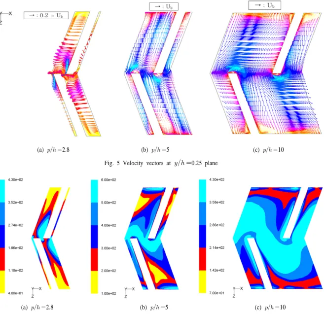
10 Fig. 5 Velocity vectors at 0.25 plane
Fig. 4 B Section(Fig. 1 )
,
.
(snaking flow) .
,
.
.
=2.8 , Fig. 4(a) B-1 Section
, .
B-1 Section ,
=2.8
1.82 1.78 1.50
=5