ISSN 2671-7972(print) ISSN 2671-7980(online) http://dx.doi.org/10.7839/ksfc.2020.17.1.044
Control of Humanoid Robots Using Time-Delay-Estimation and Fuzzy Logic Systems
Doo Sung Ahn
*Received: 14 Oct. 2019, Revised: 12 Nov. 2019, Accepted: 07 Dec. 2019
Key Words:Time-Delay-Estimation, Time-Delay-Control, Fuzzy Logic Compensator, Humanoid Robot, Simscape, Argentina Tango Walking
Abstract: For the requirement of accurate tracking control and the safety of physical human-robot interaction, torque control is basically desirable for humanoid robots. Because of the complexity of humanoid robot dynamics, the TDC (time-delay control) is practical because it does not require a dynamic model. However, there occurs a considerable error due to discontinuous non-linearities. To solve this problem, the TDC-FLC (fuzzy logic compensator) is applied to humanoid robots. The applied controller contains three factors: a TDE (time-delay estimation) factor, a desired error dynamic factor, and FLC to suppress the TDE error. The TDC-FLC is easy to execute because it does not require complicated humanoid dynamic calculations and the heuristic fuzzy control rules are intuitive. TDC-FLC is implemented on the whole body of a humanoid, not on biped legs even though it is performed by a virtual humanoid robot. The simulation results show the validity of the TDC-FLC for humanoid robots.
* Corresponding author: [email protected]
1 Department of Mechanical Design Engineering, Pukyong National University, Busan, 48513 Korea
Copyright Ⓒ 2020, KSFC
This is an Open-Access article distributed under the terms of the Creative Commons Attribution Non-Commercial License(http://
creativecommons.org/licenses/by-nc/3.0) which permits unrestricted non-commercial use, distribution, and reproduction in any medium, provided the original work is properly cited.
Nomenclature
qqq : position, velocity, and acceleration of joints M q : generalized inertia matrix
C qq : Coriolis/centripetal matrix G q : gravitational vector
F qq : friction forces
: disturbance torques
: joint torques
qd : reference input trajectory
KPKD : proportional and derivative gain
: TDE error
1. Introduction
The tracking control of trajectories for humanoid robot walking has been one of the most interesting problems. Dynamic model of a humanoid robot should be accurate to realize high accuracy-tracking control based on model-based controllers1). The nonlinear models of humanoid robots are complicated to calculate correctly, and even impossible if dynamics of humanoid robots is unknown in some cases. Therefore, it is not easy to control with traditional model-based techniques.
Also, by the virtue of stiff joints with high-ratio speed reducers of conventional humanoid robots, accurate trajectory tracking can be fulfilled with these robots;
however, excessive stiffness makes it difficult to share workspaces with humans. For the coexistence of the humanoid robots in the unstructured human living environment as an assistant, the robots should be basically safe for human-robot physical interaction.
Therefore torque control is fundamentally required for the safe interaction of human–robot.
To realize model-free torque control, TDC (time-delay control) based on TDE (time-delay estimation) technique was proposed for the control of robot manipulators in the late 1980s2). The key idea of the TDC is removing unknown nonlinear robot dynamics and implanting the desired error dynamics. It has been recently applied to humanoid robots3-4).
TDE is efficient, simple and excellent when it comes to estimating the continuous nonlinearity of robot mechanics (e.g. Coriolis and centrifugal force, gravity, viscous friction), but there occur significant errors when estimating discontinuous nonlinearities such as stiction and coulomb friction5-6). And these errors degrade TDC performance.
To reduce the TDE errors resulting from the inaccurate estimate of discontinuous nonlinearities, a third element has been added, which contains IVF (ideal velocity feedback)7) and TSM (terminal sliding mode)8). But these methods have some flaws such as calculation time and chattering. To overcome these problems, TDC with fuzzy logic compensator (TDC-FLC) was initially proposed, by researchers including me, to highly accurate tracking control of a robot manipulator9). The TDC-FLC contains three factors: a TDE factor, a desired error dynamic factor, and FLC to suppress the TDE error.
In this paper, TDC-FLC is applied to a humanoid robot for the first time although it is implemented in virtual humanoid robot. The remainder of this paper comprises as follows. In Section 2, a highly accurate tracking control of humanoid robots is designed based on TDC and FLC. In Section 3, after the optimal trajectory of a humanoid robot for Argentina tango walking is produced based PSO (particle swarm optimization), the proposed controller is verified, through 3D (three dimension) simulations in virtual environment made by Simscape under disturbance.
Finally, conclusions are drawn.
2. Proposed Control Law for Humanoid Robots
2.1 TDC for humanoid robots
The general form of the dynamic equations of a humanoid robot is as follows:
(1) where is the position, velocity, and acceleration of the joints, respectively, and
stands for the generalized inertia matrix,
the Coriolis/centripetal matrix, the gravitational vector, the friction forces,
the disturbance torques, and the joint torques.
Introducing a positive diagonal matrix, M, one can represent another expression of (1) as follows:
(2) where
(3)
The control objective is to let a robot position follow the reference input trajectory, . To this end,
let us define and .
The desired error dynamics is designed by
(4)
where , and are constant
diagonal gain matrices. , are a derivative gain and a proportional gain, respectively.
The control input can be selected as
(5) where
(6)
Here can be estimated by the TDE, as
(7)
where denotes the estimate of ,
*t-L is time-delayed value of *, and L is the estimation time delay, which is generally the sampling period in digital implementation.
From (2), one can obtain
(8) Therefore, with the equations of (5)-(8), the TDC law for a humanoid robot is drawn by
(9)
Inserting the control input (8) and (9) into humanoid robot dynamics (2), the closed-loop dynamics becomes, as
(10) If identity of is met, the closed loop equation approaches the desired error dynamics (4). The well-known stability condition for the TDC was proved by Youcef-Toumi10) and Hsia11) independently, given by
(11)
When the closed loop system is stable using the stability condition (11), the is bounded because is sum of bounded discontinuous terms and continuous terms. The bounded TDE error is defined as
(12)
Then the closed loop dynamics with the TDC (9) becomes
(13)
The TDE error is approaches to 0 in operating time of humanoid robot unless a pulse-type error which results from discontinuity of Coulomb friction at velocity reversal3) happens.
2.2 Proposed control using the fuzzy logic
To reduce the TDE error, we adopted the ISS (integral sliding surface), as
(14)
Achieving (4) is equivalent to obtain the ISS, = 0.
The control input can be designed as:
(15) and
(16) Then, combining (7), (8), (15) and (16), the proposed control law for a humanoid robot can be expressed by
(17)
In the proposed control, (17), stands for the TDE part, injects the desired error dynamics, and corrects the TDE error with ISS (14). Substituting the control input (17) and (14) into (2) yields the closed loop dynamics
(18) or
(19)
If the fuzzy s-dynamics (19) is asymptotically stable, and is bounded, the close loop dynamics is also bounded7).
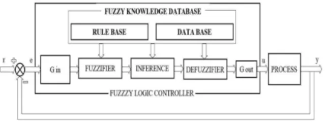
(20) Generally, whether a fuzzy control design, shown in Fig. 1, will be stable is a somewhat open question.
Fig. 1 Fuzzy logic controller
A fuzzy controller is constructed by the components such as fuzzy sets, fuzzy logic operators, fuzzy rules, the fuzzy inference method, and the defuzzifier. The organization of a fuzzy controller will depend on types of the components. There are various ways to construct
an asymptotically stable fuzzy controller12-13). In this paper, Mamdani-type FIS(fuzzy inference system) is employed to construct an asymptotically stable fuzzy s-dynamics (20). Fuzzy rules that mimic a conventional PD controller are adopted as follows14):
R1 : if erris NB AND Δ err is N then output is HIGH R2 : if erris NB AND Δ err is ZE then output is VH R3 : if erris NB AND Δ err is P then output is VH R4 : if erris NM AND Δ err is N then output is HIGH R5 : if erris NM AND Δ err is ZE then output is VH R6 : if erris NM AND Δ err is P then output is VH R7 : if erris NS AND Δ err is N then output is HIGH R8 : if erris NS AND Δ err is ZE then output is HIGH R9 : if erris NS AND Δ err is P then output is MED R10 : if erris Z AND Δ err is N then output is MED R11 : if erris Z AND Δ err is ZE then output is MED R12 : if erris Z AND Δ err is P then output is MED R13 : if erris PS AND Δ err is N then output is MED R14 : if erris PS AND Δ err is ZE then output is LOW R15 : if erris PS AND Δ err is P then output is LOW R16 : if erris PM AND Δ err is N then output is HIGH R17 : if erris PM AND Δ err is ZE then output is VH R18 : if erris PM AND Δ err is P then output is VH R19 : if erris PB AND Δ err is N then output is LOW R20 : if erris PB AND Δ err is ZE then output is VL
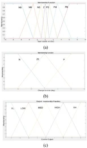
The err, Δerr and output functions are transformed into fuzzy numbers based on membership functions as shown in Fig. 2. The err and Δ error represent the deviation of measured value from reference value and the change in error between two successive time steps, respectively. In Fig. 2, the width of the Z set membership function is relatively narrow compared with other membership functions, to increase control accuracy in the surrounding of the zero. Triangle-shaped function and trapezoidal-shaped function are adopted for err and Δ err membership functions for the FIS, given by
(a)
(b)
(c)
Fig. 2 Fuzzy values for (a) err , (b) Δ err and (c) output fuzzy variables
To obtain the fuzzy control surface, Mandani min implication operator and center of area defuzzification are used. The control hypersurface of the FIS is depicted in Fig. 3, when there are with all 21 rules.
Fig. 3 The control hypersurface when there are with all 21 rules.
3. Simulation
3.1 Optimal trajectory of humanoid robot for Argentina tango walking15).
For producing of the stable and natural walking in
Argentine tango, PSO( is used under the following Walking and Cost Conditions which represent the characteristics of Argentina tango walking.
Walking Condition 1: For the correct embracement upper-body must be leaned forward to some degree in the sagittal plane and keeps vertical in the coronal plane.
Walking Condition 2: For the natural tango walking, the free-swing leg maintains to be parallel to supporting leg.
Walking Condition 3: The free-swing foot during walking should be parallel and above to ground to avoid danger that the heel or toe of the free-swing foot crash into ground.
Walking Condition 4: All joints in the sagittal and coronal plane of upper-body should maintain the initial angles during dance of Argentine tango.
Cost Condition 1: Angles of both knees should keep positive value in order to avoid disgusting motion of legs and damage of joints.
Cost Condition 2: For the stable step, free-swing foot should follow the reference optimal trajectory in the sagittal and coronal plane.
Cost Condition 3: Reference trajectory of ZMP(zero moment point) should be located in the stability region of biped humanoid robot.
3.2 Physical modeling using Simscape
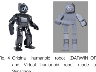
For the simulations of humanoid robot walking, a virtual humanoid robot is used. This is first designed by Solidworks16), as shown in Fig. 4, which is basically DARWIN-OP robot made by Robotis Ltd17). Then it is converted into a virtual humanoid robot made in the Simscape18) environment. The humanoid robot is 45 cm tall, weighs 2.8kg, and has 20 DOF. It has originally 3 DOF in the transverse plane, 11 DOF in the sagittal plane, and 6 DOF in the coronal plane. For the dance of Argentina Tango, 20 DOF is deficient. Additional 4 DOF in upper-body (2 DOF for each wrist and 2 DOF for each shoulder) are reinforced for the necessity of embracing a partner. The center of mass is located in the center of its pelvis. The location is optimal for correct balancing and adequate allocation of moment inertia during gait.
Fig. 4 Original humanoid robot (DARWIN-OP) and Virtual humanoid robot made by Simscape
Fig. 5 shows schematic block diagram of the proposed TDC-FLC controller in environments with disturbance. The proposed TDC-FLC controller is implemented in left ankle joint of sagittal plane under Simscape environment.
Fig. 5 Block diagram of the proposed TDC-FLC controller in environments with disturbance
3.3 Simulation
In this section, the performance of the proposed TDC-FLC is verified, through 3D simulations in Simscape virtual environment under disturbance. The step length is 5 cm and upper-body maintains vertical during walking. Optimal walking trajectory starts from left foot-supported position and finishes at right foot-supported position. The coefficient of spring stiffness and damping of left ankle joint in sagittal plane are given 10 N*m/rad and 0.1 N*m/(rad/s), respectively. The proportional and derivative gain, KP
and KD, are set to 100 and 20, respectively. The estimation time delay is L=1 ms, fuzzy gain K=2, and
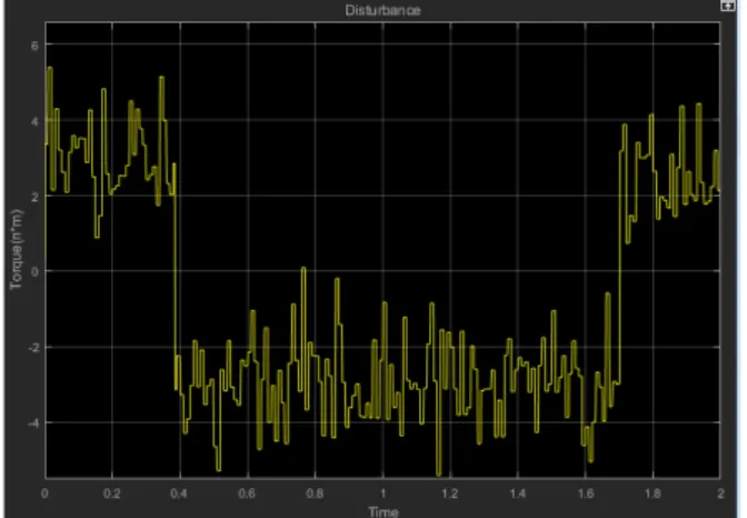
M=1 are chosen. Disturbance consisted of Coulomb
friction with a frictional force of 3 N, viscous friction with a friction coefficient of 0.05 and band-limited white noise with a noise power of 0.01. Fig. 6 shows disturbances occurring during one step. Fig. 7 and 8 show the reference trajectory obtained from PSO and actual response of the left ankle in sagittal plane under TDC without/with FLC, respectively. Root mean square of position error of left ankle joint in sagittal plane is reduced from 1.4036 to 0.4531. Fig. 9 represents input torque of left ankle joint in sagittal plane. The splashing of the control input is considered to be a problem in numerical analysis rather than the proposed controller.
Fig. 10 shows the successive 3D view of humanoid robot in Argentina tango walking when the left foot is supported.
Fig. 6 Disturbance composed of Coulomb friction and white noise
Fig. 7 Reference trajectory obtained by PSO and actual response of the left ankle in sagittal plane under TDC without FLC
Fig. 8 Reference trajectory and actual response of the left ankle in sagittal plane under TDC with FLC
Fig. 9 Input torque of left ankle joint in sagittal plane
Fig. 10 Successive 3D view of humanoid robot in Argentina tango walking
4. Conclusion
For the requirement of both the safety of physical human-robot interaction and accurate tracking control, torque control is fundamentally desirable for humanoid robots. Considering nonlinearity and complexity of
humanoid robot dynamics, TDC was a kind of good solution. In this paper, fuzzy logic combined with the TDC technique is applied to a virtual humanoid robot in order to suppress the TDE. The proposed controller includes three factors: the TDE factor to estimate and cancel continuous nonlinearities of robot dynamics, the injection factor to endow desired dynamics, and the correcting factor using integral sliding mode and Mamdani-type FIS. The Mamdani-type FIS is established based on common sense rules. The proposed controller with well-established FIS functions is highly intuitive, accurate, and efficient. By virtue of the TDE part, the proposed controller exhibits the simplicity and efficiency of TDC. The simulation results shows that the proposed TDC-FLC could be a good solution to achieve good tracking performance for humanoid robots.
Acknowledgement
This work was supported by a Research Grant of Pukyong National University (2019 year).
References
1) M. Uebel, I. Minis and K. Cleary, “Improved computed torque control for industrial robots”, Proceedings of 1992 IEEE International Conference on Robotics and Automation, Vol.1, pp.528-553, 1992.
2) T. C. S. Hsia, “A new technique for robust control of servo systems,” IEEE Transactions on Industrial Electronics, Vol.36, No.1, pp.1-7, 1989.
3) M. Jin, J. Lee and N. G. Tsagarakis, “Model-Free Robust Adaptive Control of Humanoid Robots With Flexible Joints”, IEEE Transactions on Industrial Electronics, Vol.64, No.2, pp.1706-1715, 2017.
4) D. S. Ahn, “Time-Delay Control for the Implementation of the Optimal Walking Trajectory of Humanoid Robot”, Journal of Drive and Control, Vol.15, No.3, pp.1-7, 2018.
5) M. Jin et al., “Practical Nonsingular Terminal Sliding-Mode Control of Robot Manipulators for High-Accuracy Tracking Control”, IEEE Transactions on Industrial Electronics, Vol.56, No. 9, pp.3593-3601, 2009.
6) J. H. Heo, B. Y. You and J. W. Kim, "Tension Control of a Winding Machine using Time-delay Estimation", Journal of Drive and Control, Vol.15, No.3, pp.21-28, 2018.
7) J. Lee, P. H. Chang and R. S. Jamisola, “Relative Impedance Control for Dual-Arm Robots Performing Asymmetric Bimanual Tasks”, IEEE Transactions on Industrial Electronics, Vol.61, No.7, pp.3786-3796, 2014.
8) M. Jin et al., “High-Accuracy Tracking Control of Robot Manipulators Using Time Delay Estimation and Terminal Sliding Mode”, International Journal of Advanced Robotic Systems, Vol.8, No.4, pp.65-78, 2011.
9) H.-J. Bae et al., “Control of Robot Manipulators Using Time-Delay Estimation and Fuzzy Logic Systems,” Journal of Electrical Engineering and Technology, Vol.12, No. 3, pp.1271-1279, 2017.
10) K. Youcef-Toumi and O. Ito, “A Time Delay Controller for Systems With Unknown Dynamics”, Journal of Dynamic Systems, Measurement, and Control, Vol.112, No.1, pp.133-142, 1990.
11) T. C. Hsia, and L. S. Gao, “Robot manipulator control using decentralized linear time-invariant time-delayed joint controllers,” Proceedings of IEEE International Conference on Robotics and Automation, pp.2070-2075, 1990.
12) H. Ying, “Structure and stability analysis of general mamdani fuzzy dynamic models,” International Journal of Intelligent Systems, Vol.20, No.1, pp.103-125, 2005.
13) M. Margaliot and G. Langholz, “Fuzzy Lyapunov- based approach to the design of fuzzy controllers”, Fuzzy Sets and Systems, Vol.106, No.1, pp.49-59, 1999.
14) L. H. Tsoukalas and R. E. Uhrig, Fuzzy and Neural Approaches in Engineering, John Wiley &
Sons, New York, pp.151-176, 1997.
15) D. S. Ahn, "Biped Walking of a Humanoid Robot for Argentina Tango", Journal of Drive and Control, Vol.13, No.4, pp.52-58, 2016.
16) http://www.solidworks.co.kr 17) http://www.robotis.com 18) http://www.mathworks.co.kr