원형 미소 채널 내 계면장력이 Plug flow 압력강하에 미치는 영향에 관한 선행 연구
이치영† · 이상용*
Effect of Interfacial Tensions on Pressure Drop of Two-Phase Plug Flow in Round Mini-channels
- A Preliminary Investigation -
Chi Young Lee and Sang Yong Lee
Key Words : Plug flow(Plug flow), Mini-channel(미소채널), Interfacial tension(계면장력), Wettability(젖음성), Pressure drop(압력강하)
Abstract
In the present experimental study, the effect of interfacial tensions on pressure drop of air-water two-phase flow in round mini-channels was investigated. A glass (highly wettable) tube and a Teflon (poorly wettable) tube, both in 350 mm length but 1.8 mm and 1.59 mm in inner diameters each, were used for the tests. All the experiments were performed only in the plug flow regime, confirmed by visualization. In the glass tube, the gas plugs were surrounded by the liquid film along the inner periphery. On the other hand, the inner wall remained dry at the gas portion in the Teflon tube. The pressure drop of the plug flow in the Teflon tube (without the liquid film) appeared much larger than in the glass tube (with the liquid film) due to dissipation of energy by movement of the wetting lines. In this paper, various correlations on the two-phase pressure drop of plug flows were compared and a modified correlation was proposed, taking account of the surface wettability.
기호설명 D : 관 내경(m)
ED : 에너지 소산 무차원 변수 Fr : 프라우드수
f : 마찰계수
G : 질량유속(kg/m2s) g : 중력가속도(= 9.8 m/s2) L : 관 길이(m)
ΔP : 압력강하(Pa) Re : 레이놀즈수 U : 겉보기 속도(m/s) We : 웨버수
X : 마티넬리수 x : 건도 Greek symbol
Φ : Two-phase multiplier
ε : 단위 질량당 에너지 소산(W/kg) θ : 접촉각(°)
μ : 점성계수(Ns/m2) ρ : 밀도(kg/m3) σ : 표면장력(mN/m) υ : 동점성계수(m2/s) Subscript
L : 2 상 유체중 액체만 고려
† 한국과학기술원 기계공학과 E-mail : [email protected]
TEL : (042)869-5026 FAX : (042)869-8207 * 한국과학기술원 기계공학과
LO : 2 상 유체 전체를 액체라 가정 TP : 2 상 유체
V : 2 상 유체중 기체만 고려 VO : 2 상 유체 전체를 기체라 가정
1. 서 론
큰 채널에서의 2 상 유동에서, Capillary force 는 Inertia force 와 Viscous force 에 비해 무시할 만하였다. 하지만 Device 가 작아짐에 따라 Capillary force 가 2 상 유동 현상에 중요한 역할을 하게 되었다. 이 경우, 표면장력(액체와 기체의 Interaction)뿐 아니라 관의 재질이 2 상 유동 양식에 영향을 미치는 중요한 Factor 가 된다.
채널의 재질이 2 상 유동 양식에 미치는 영향에 관한 연구는 Barajas and Panton(1), Iguchi and Terauchi(2-4), Nakamura et al.(5), Lee and Lee(6-7) 등에 의해 이루어져 왔다.
Barajas and Panton(1)은 접촉각이 다른 4 개의 수평관(Pyrex, Polyethylene, Polyurethane, FEP)과 물- 공기를 이용하였다. 관의 접촉각은 각각 34°, 61°, 74°, 106° 이고, 관의 내경은 모두 1.6 mm였다. Pyrex tube의 Wavy flow영역은 접촉각이 큰 경우 Rivulet flow로 변화하였고, FEP와 같이 젖음성이 좋지 않은 경우에 2 상 유동 양식의 Transition line이 다른 재질의 관들과는 큰 차이를 보였다. 하지만 Plug flow에서 Slug flow로의 Transition line은 접촉각에 크게 영향받지 않았다.
Iguchi and Terauchi(2-4)은 Normal gravity와 Microgravity환경하에서 접촉각이 다른 3 개의 수직관과 물-공기를 이용하였다. 사용한 관의 내경은 5 mm, 10 mm, 15 mm이고, 접촉각은 36°, 77°, 104°였다. 그들이 관심을 가진 2 상 유동 양식 영역은 Bubbly flow와 Slug flow 영역이었다. 그들은 Bubbly flow와 Slug flow의 유동 양식을 가시화하고, Liquid slug와 Bubble의 평균 상승 속도(Mean rising velocity) 와 길이에 젖음성이 어떠한 영향을 미치는지 보고하였다. Microgravity 환경하에서 Liquid slug와 Bubble의 평균 상승 속도 및 길이에
젖음성의 영향이 작었음을 보고하였고
실험데이터를 바탕으로 예측식을 제안하였다.
Nakamura et al.(5)은 접촉각이 7°, 45°, 146°이고, 내경이 20 mm의 수직관을 이용하였다. 친수성일 때 (θ=7°, 45°) Churn flow와 Annular flow가 관찰된 영역은, 소수성일 때 (θ=146°) Inverted churn flow와 Droplet flow가 관찰되었다. 그들은 Force balance analysis를 바탕으로 Slug flow와 Inverted churn flow, Inverted churn flow와 Droplet flow간 Transition criteria를 제안하였다.
Lee and Lee(6)는 물-공기뿐 아니라 메탄올-공기를 원형 수평 유리관과 Teflon관에 흘려서, 기체- 액체-고체의 조합이 2 상 유동 양식의 세부
형태에 미치는 영향을 보고하였다. 물-공기-유리관 조합의 경우 Plug flow, Slug flow영역에서 기체가 존재하는 부분의 주위에 액막이 존재하는 형태를 보였으나, 물-공기-Teflon의 조합에서는 액막이 존재하지 않았고, 기체의 유속이 증가함에 따라 Rivulet flow로 발달하였다. 반면에 메탄올-공기-
테플론 조합에서는 물-공기-유리관의 조합과
유사하게 기체의 부분에 액막이 존재하는 Plug flow와 Slug flow가 관찰되었다.
Lee and Lee(7)는 미소 채널에서 자주 관찰되는 Plug flow영역에 관심을 가지고 물-공기의 2 상 유체를 이용하여 유리관 및 Teflon관내에서 2 상 유동 양식의 세부 형태가 다르게 나타나는 이유를 Interfacial energy관점에서 설명하였으며, 2 상 유동의 세부 형태 차이가 압력강하에 미치는 영향을 실험을 통해 보고하였다. 또한 같은 2 상 유체 조건에서 Teflon관(소수성)내의 압력 강하가 유리관(친수성)내의 압력강하보다 크게 나타났고, 이는 Moving wetting line에 의한 에너지 소산(8-10)이 존재하기 때문이라 언급하였다.
본 연구는 Lee and Lee(7)의 연구와 연장선에 있는 내용으로, 미소채널 내 Plug flow의 압력강하에 관한 실험데이터를 기존 상관식과 비교하여 보고, Moving wetting line에 의한 에너지 소산을 고려한 상관식을 제안하고자 한다.
2. 실험장치 및 실험조건
2.1 실험장치
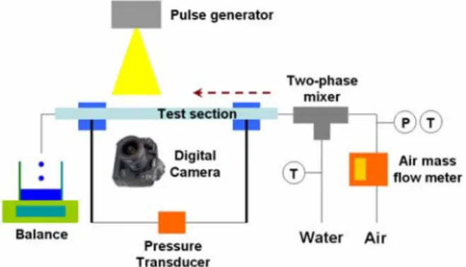
실험장치의 개략도를 Fig. 1 에 나타내었다. 물- 공기를 사용하였고, 실험시 사용한 원형관은 내경 1.8 mm 의 유리관(친수성)과 내경 1.59 mm 인 Teflon 관(소수성)이었으며 길이는 350 mm 로 동일 하였다. 관 입출구의 차압을 측정하기 위해 차압 계를 설치하였으며, 측정 가능한 영역은 0-3.5 kPa 이었다. 공기의 유량은 질량 유량계(0-1 liter/min)를
Fig. 1 Schematic diagram of experimental setup
이용하였고, 물의 유량은 일정시간(5 분)동안 흘려 준 물의 무게를 측정하여 환산하였다. 실험시 2 상 유동 양식을 확인하기 위하여 Digital camera 와 Pulse generator 를 이용하여 가시화하였다.
2.2 실험조건
실험을 수행한 공기와 물의 겉보기 속도 조건은 각각 0.15-0.6 m/s와 0.03-0.25 m/s 이었다. 모든 실 험은 Plug flow 영역에서 수행하였다. Lee and
Lee(6,7)의 실험결과를 바탕으로 실험조건을 예측하
였으며, 실험시 Digital camera 와 Pulse generator를 이용하여 가시화함으로써 유동양식이 Plug flow인 지 확인하였다.
본 실험조건에서 관찰된 Plug flow 의 형태는 유 리관의 경우 기체 Plug 주위에 액막이 존재하는 형태를 보인 반면, Teflon 의 경우 기체 Plug 주위 에 액막이 존재하지 않았다. 가시화 사진 및 Illustration 을 Fig. 2 에 나타내었다.
3. 실험결과 및 고찰
3.1 실험데이터와 기존 상관식의 비교
Moving wetting line에 의한 에너지 소산이
존재하지 않는 유리관에 의한 압력강하
실험데이터와 그러한 영향을 고려하지 않은 기존 상관식을 비교하여 보았다. 비교한 기존 상관식은 균질 모델(11), Chisholm 상관식(12), Friedel 상관식(13)으로써, 균질 모델(11)과는 달리 Chisholm 상관식(12)과 Friedel 상관식(13)은 Separated flow
(a) Plug flow with liquid film (UV=0.58 m/s, UL=0.044 m/s)
(b) Plug flow without liquid film (UV=0.42 m/s, UL=0.090 m/s)
Fig. 2 Visualization and illustration of the plug flow of the air-water mixture in the glass tube (a) and the Teflon tube (b) (Lee and Lee(6,7)).
Fig. 3 Comparison between the experimental data of air-water mixture with the glass tube and the homogeneous flow model(11).
model이다. Chisholm 상관식(12)은 2 상 유동의 압력강하를 예측하는 대표적인 상관식으로 널리 인용되고 있고, Friedel 상관식(13)은 액체의 표면장력을 고려하였다는 점에서 특징이 있다.
균질 모델(11)의 기본 형태는 다음과 같다.
2
2 TP TP
TP
U D f L
P = ρ
Δ (1) Figure 3 에 유리관의 압력강하 데이터와 균질 모델(11)에 의한 예측치를 비교하였다. 균질 모델(11) 은 본 실험영역에서 유리관의 압력강하 데이터를 비교적 정확하게 예측하였다. 이는 유리관에서 관 찰된 Plug flow의 경우 액체와 기체의 속도가 유사 하고, 유동의 단면 형상이 안쪽에 기체가 흐르고 기체 Plug를 액막이 둘러싸인 모양으로 속도 구배 가 방향에 상관없이 일정하기 때문으로 판단된다.
Ungar and Cornwell(14), Triplett et al.(15), Chen et al.(16), Pehlivam et al.(17) 등의 기존 연구에서도 균질 모델
(11)은 미소 채널에서의 2 상 유동 압력강하를 비교 적 정확하게 예측하고 있다고 보고하고 있다.
Chisholm 상관식(12)의 Two-phase multiplier는 다 음과 같다.
2
2 C 1
L 1 ⎟
⎠
⎜ ⎞
⎝ +⎛
⎟⎠
⎜ ⎞
⎝ +⎛
= X X
Φ (2)
Chisholm 상관식(12)에 의한 예측치와 실험데이터 를 Fig. 4 에 비교하였다. Chisholm 상관식(12)은 본 실험조건에서 실험데이터를 Under-prediction하고 있음을 알 수 있다. 이러한 경향은 Chen et al.(16)이 나 Pehlivam et al.(17) 등이 보고한 것과 유사하다.
Fig. 4 Comparison between the experimental data of air-water mixture with the glass tube and the Chisholm correlation(12).
Friedel 상관식(13)의 Two-phase multiplier는 다음과 같다.
0.035 0.045
3 1 2
2
LO Fr We
A A 24 . A + 3
=
Φ (3)
( )
LO V
VO 2 L 2
1 1
f x f x
A ρ
+ ρ
−
= (4)
224 . 0 78 . 0
2 (1 )
A =x −x (5)
7 . 0
L V 19 . 0
L V 91 . 0
V L
2 1
A ⎟⎟⎠
⎜⎜ ⎞
⎝
⎛ −
⎟⎟⎠
⎜⎜ ⎞
⎝
⎟⎟ ⎛
⎠
⎜⎜ ⎞
⎝
=⎛
μ μ μ
μ ρ
ρ (6)
2 TP 2
Fr gDρ
= G ,
σ ρTP
2
We G D
= (7)
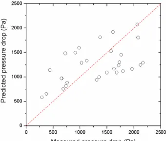
Fig. 5 Comparison between the experimental data of air-water mixture with the glass tube and the Friedel correlation(13).
Table 1 Comparison between the experimental data and correlations
Correlations Deviation (%) Homogeneous flow model(11) + 13.2
Chisholm correlation(12) - 42.5 Friedel correlation(13) + 45.9
Δ 100 Δ (%) Δ
Deviation
Measured Measured
Predicted− ×
= P
P P
Friedel 상관식(13)은 본 실험데이터를 Over- prediction하였다 (Fig. 5). Triplett et al.(15), Chen et al.(16), Pehlivam et al.(17), Wang et al. (18) 등의 결과 역 시 물-공기의 2 상 유동 압력강하를 예측함에 있 어서 Friedel 상관식(13)은 Over-prediction하고 있다 고 보고하고 있다. 반면에 Chen et al.(16) ,Yang et al.(19) 등은 표면장력이 물보다 작은 냉매의 경우 에는 Friedel 상관식(13)이 2 상 유동 압력강하를 비 교적 잘 예측한다고 이야기하고 있다.
앞서 언급한 3 가지 종류의 기존 상관식과 유리 관내 물-공기를 이용한 2 상 유동의 압력강하 실 험데이터를 비교한 결과를 Table 1 에 정리하였다.
본 연구의 실험데이터를 가장 정확하게 예측한 2 상 유동 압력강하 상관식은 균질 모델(11)이었으며, 오차는 + 13.2 %로 나타났다.
3.2 새로운 2 상 유동 압력강하 Model
액막이 존재하지 않는 Plug flow 에 존재하는 Moving wetting line 에 의한 에너지 소산을 고려한 2 상 유동 압력강하 상관식을 제안하고자 한다.
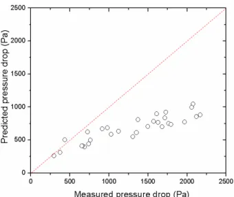
먼저 Moving wetting line이 존재하지 않는 유리 관내 물-공기의 2 상 유동 압력강하를 가장 잘 예 측하였던 균질 모델(11)과 Teflon의 2 상 유동 압력 강하 실험데이터를 비교하여 보았다 (Fig. 6). 균질 모델은 Teflon내 2 상 유동 압력강하 데이터를 Under-predition하는 경향을 보였고 이는 Moving wetting line에 의한 에너지 소산의 영향을 균질 모 델이 반영하지 못하고 있기 때문이다.
Moving wetting line 이 존재하는 경우의 Plug flow 의 새로운 2 상 유동 압력강하 상관식의 기본 형 태는 다음과 같다.
line wetting Moving flow
phase -
Two P
P
P=Δ +Δ
Δ (8)
우변의 첫번째 항은 물-공기의 2 상 유동에 의 한 압력강하의 영향을 나타내고, 두번째 항은 Moving wetting line이 존재하여 나타나는 에너지 소산에 의한 압력강하 영향을 나타낸다. 2 상 유동 에 의한 압력강하의 영향은 유리관의 실험데이터 와 기존 상관식의 비교 결과를 토대로 볼 때, 균 질 모델(11)을 사용하는 것이 좋다고 판단된다.
Fig. 6 Comparison between the experimental data of air-water mixture with the Teflon tube and the homogeneous flow model(11).
Moving wetting line 에 의한 에너지 소산이 압력 강하에 미치는 영향은 Teflon 관에 대한 실험데이 터와 균질 모델에 의한 예측치간 차이로 예측된다.
유체의 단위 질량당 에너지 소산과 압력강하간 의 관계는 식(9)와 같이 표현가능하다(20-22).
L P U
ε = ρΔ (9) Darcy equation 은 식 (10)과 같이 표현되고,
Δ 2
U2
D f L
P= ρ (10) 식 (9)와 (10), Re 를 이용하면 식 (11)과 같은 무 차원 변수를 정의할 수 있다.
ED 2Re
3 3
4 = f =
D ν
ε (11)
식 (11)의 무차원변수 ED 는 “Energy dissipation parameter”라 정의되고, Re 의 함수로 표현된다. 액 체 Plug 이동시 Moving wetting line 에 의한 에너 지 소산은 접촉각과 관련있고, 식 (11)의 Fiction factor, f 는 식 (12)과 같이 표현될 수 있다.
) cos 1 ( Re
a bL + θ
=
f (12) Teflon 관의 실험데이터를 이용하여 식(12)의 상 수 a, b 를 Data fitting 을 통하여 결정하면, 최종적 으로 식 (13)과 같은 식이 도출된다.
( )
[
ρ 227Re ρ 1 cosθ2
2 L L 1 - L 2
TP
TP + +
=
Δ f U U
D P L
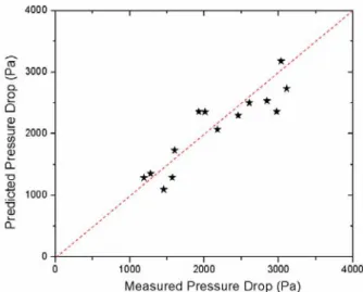
Fig. 7 Comparison between the experimental data of air-water mixture with the Teflon tube and the modified correlation.
Figure 7 에 본 연구의 Teflon 관 내 압력강하 실 험데이터와 식 (13)에 의한 예측치의 비교 결과를 나타내었다. 오차는 -2.6 %로 Teflon 관 내 압력강 하 실험데이터와 잘 맞았다. 식 (13)은 액막이 존 재하지 않는 Plug flow 의 압력강하를 표현하는 식 으로써, Moving wetting line 에 의한 에너지 소산을 고려했다는 점에서 의미가 있다 하겠다.
]
(13)4. 결론
본 연구에서는 계면장력이 Plug flow regime 에서 압력강하에 미치는 영향을 알아보기 위해, 물-공 기의 2 상 유체와 원형 유리관 및 Teflon 관을 이 용한 실험을 실시하였다.
친수성 재질(유리관)에서 Plug flow의 기체 plug 주위에는 액막이 존재하였고, 본 실험 조건에서 압력강하 실험데이터를 가장 잘 예측한 상관식은 균질모델(11)이었다. Chisholm 상관식(12), Friedel 상관 식(13)과 비교 결과는 기존 다른 연구자들의 결과 와 유사한 경향을 나타내었다.
소수성 재질(Teflon 관)의 Plug flow 의 경우 기체 Plug 주위에는 액막이 존재하지 않았다. 소수성 재질에서의 압력강하는 Moving wetting line 에 의한 에너지 소산때문에 친수성 재질의 압력강하보다 크게 측정되었다.
원형 유리관과 Teflon 관내 압력강하 실험데이터 를 통해, 소수성 재질의 Plug flow 에서 Moving wetting line 이 존재할 때 그로 인한 에너지 소산을 고려한 2 상 유동 압력강하 상관식을 식 (13)과 같 이 제안하였다.
6
후 기
본 연구는 과학재단의 특정기초연구사업(2 상유 동 양식 분석을 통한 PEMFC 채널 내 water blocking 문제에 관한 연구, R01-2006-000-11298-0), KAIST 기본연구, BK-21 의 일부 지원을 받아 수행 되었으며 이에 감사드립니다.
참고문헌
(1) Barajas, A. M. and Panton, R. L., 1993, “The effects of contact angle on two-phase flow in capillary tubes,”
Int. J. Multiphase Flow, Vol. 19, pp. 337-346.
(2) Iguchi, M. and Terauchi Y., 2000, “Rising behavior of air-water two-phase flows in vertical pipe of poor wettability,” ISIJ international, Vol. 40, pp. 567-571.
(3) Iguchi, M. and Terauchi Y., 2001a, “Boundaries among bubbly and slug flow regimes in air-water two- phase flows in vertical pipe of poor wettability,” Int. J.
Multiphase Flow, Vol. 27, pp. 729-735.
(4) Iguchi, M. and Terauchi Y., 2001b, “Microgravity effects on the rising velocity of bubbles and slugs in vertical pipes of good and poor wettability,” Int. J.
Multiphase Flow, Vol. 27, pp. 2189-2198.
(5) Nakamura, D., Tamura, N., Hazuku, T., Takamasa, T.
and Hibiki, T., 2005, “Effect of surface wettability on flow patterns in a vertical gas-liquid two-phase flow,”
13th International Conference on Nuclear Engineering, ICONE13-50508.
(6) Lee, C. Y. and Lee, S. Y., 2006, “Effect of Interfacial Tensions on Transition of Two-phase Flow Pattern in Mini-channels,” The 3rd ICFD (International Conference on Flow Dynamics), OS5-44.
(7) Lee, C. Y. and Lee, S. Y, 2007, “Effect of Interfacial Tensions on the Behavior of Two-Phase Plug Flow in Round Mini-channels,” The Eighteenth International Symposium on Transport Phenomena (Submitted).
(8) Son, S. Y. and Allen, J. S., 2005, “Visualization and predictive modeling of two-phase flow regime transition with application towards water management in the gas- flow channels of PEM fuel cells,” Proceedings of IMECE2005, IMECE2005-82422.
(9) Blake, T. D., 2006, “The physics of moving wetting lines,” Journal of Colloid and Interface Science, Vol.
299, pp. 1-13.
(10) de Gennes, P.G., 1985, “Wetting: statics and dynamics,” Reviews of Modern Physics, Vol. 57, pp. 827
-863.
(11) Collier, J. G. and Thome, J. R, 1994, Convective boiling and condensation (3rd edition), Oxford.
(12) Chisholm, D., 1967, “A theoretical basis for the Lockhart-Martinelli correlation for two-phase flow,” Int.
J. Heat Mass Transfer, Vol. 10, pp. 1767-1778.
(13) Friedel, L, 1979, “Improved friction pressure drop correlations for horizontal and vertical two-phase pipe flow,” Presented at the European Two-phase Flw Group Meeting, Ispra, Italy, Paper E2, June.
(14) Ungar, E. K. and Cornwell, J. D., 1992, “Two- pasepressure drop of ammonia in small diameter horizontal tube,” AIAA paper 92-3891.
(15) Triplett, K. A., Ghiaasiaan, S. M, Abdel-Khlik, S. I., KeMouel, A. and McCord, B. N., 1999, “Gas-liquid two- phase flow in microchannels Part II: void fraction and pressure drop,” Int. J. Multiphase Flow, Vol. 25, No. 3, pp. 395-410.
(16) Chen, I. Y., Yang, K. S. and Wang, C. C., 2002,
“An empirical correlation for two-phase frictional performance in small diameter tubes,” Int. J. Heat Mass Transfer, Vol 45, pp. 3667-3671.
(17) Pehlivan, K., Hassan, I. and Vaillancourt, M., 2006,
“Experimental study on two-phase flow and pressure in millimeter-size channels,” Applied Thermal Engineering, Vol. 26, pp. 1506-1514.
(18) Wang, C. C., Yang, K. S., Chang, Y. J. and Lu, D.
C., 2000, “Characteristics of air-water two-phase flow in a 3-mm smooth tube,” Can. J. Chem. Eng., Vol. 78, pp.
1011-1016.
(19) Yang, K. Y., Chen, I. Y., Hu, R., Wang, C. C., 2002,
“Some Observations of the Two-Phase Flow Characteristics of R-125 and R-407C within a 3-mm Diameter Tube,” ASHRAE Trans., Vol. 108. pp. 529-536.
(20) Sano, Y. and Usui, H., 1982, “Evaluation of heat transfer promoters by the fluid dissipation energy,” Heat transfer Jpn Res, Vol. 11, pp. 91-96.
(21) Tandiroglu, A. and Ayhan, T., 2006, “Energy dissipation analysis of transient heat transfer for turbulent flow in a circular tube with baffle inserts,”
Applied thermal engineering, Vol. 26, pp. 178-185.
(22) Yilmaz, M., Yapici, S., Comakli, O. and Sara, O. N., 2002, “Energy correlation of heat transfer and enhancement efficiency in decaying swirl flow,” Int. J.
Heat Mass Transfer, Vol. 38, pp. 351-358.