14. p.787 Axial Vibration Damper Modelling Method on the Two Stroke Low Speed Diesel Engine
7
0
0
전체 글
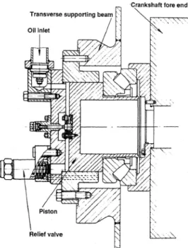
(2) Myeongho Song et al. ; Axial Vibration Damper Modelling Method on the Two Stroke Low Speed Diesel Engine. AVD를 적용하기 시작하였다. 그 당시에는 AVD는 크랭크축 선단에 별도 구조로 설치되었다. 현재는 실 린더 수에 관계없이 선박용 2행정 저속 디젤엔진에. 서 연장되어 있다. 그리고 좀 더 상세한 우측 그림에 서 피스톤에 홀이 있는데 양 실린더 사이에 오일의 통 로로 오리피스 역할을 한다. AVD 구조와 역할은 최. 표준으로 모두 콤팩트 구조를 적용하고 있으며 감쇠 와 함께 크랭크축의 종진동 자체는 큰 문제가 없다. 그러나 종진동에 의해서 발생하는 추력변동력 때문에. 근 개발된 제품과 비교하여 손색이 없다. Fig. 3은(2) Fig. 2에서 오리피스의 홀 크기에 따른 종진폭을 측정 한 결과로 비틀림진동에 의한 종진폭을 감소시킬 수 있다. 특히 엔진회전수가 120 r/min ~ 130 r/min에서 홀이 없을 경우 종진동이 오히려 증가함을 보이며 오 리피스 홀을 조정하여 최적화가 요구된다. 그 당시에. 선체진동이 문제가 되어 특정한 영역에서 추력을 줄 이기 위해 AVD의 감쇠 조정에 관한 연구를 한 사례 도 있다(3). 이 논문은 11G90ME엔진을 주 기관으로 한 추진 축계의 종진동을 연구 모델로 선정하여 AVD의 모델 링 방법에 따른 이론적 해석과 측정 자료를 통해서 종진동 특성을 검토하고자 한다.. 2. 종진동 댐퍼 구조와 모델링 방법 Fig. 1은(1) 디튜너의 구조를 보이며 순수한 종진동 을 줄일 목적으로 사용되기 때문에 중간에 미첼 (Michell)형 추력 베어링 대신 롤러 베어링이 들어있 어 크랭크축 선단과 기계적으로 접촉되며 종 방향으 로 강성을 유지한다. 이후 1960년대 초기 이탈리아 GMT사에서 개발한 종진동을 위한 제동장치를 Fig. 2 에 보인다(2). 이 그림에서 AVD의 실린더는 엔진 프레 임 구조와 연결되어 있고 피스톤은 크랭크축 끝단에. 도 종진동에 의해서 크랭크축의 굽힘응력이 증가하고 비틀림진동 응력과 합성되어 크랭크축은 강도상 문제 가 될 수 있었다. 그 후 MAN ES사가 연료절약형 장 행정인 MC엔진을 개발하여 소개하면서 크랭크축의 종진동뿐만 아니라 종진동에 의해서 발생하는 추력변 동력이 선체상부에 전달되어 종종 문제가 되어 왔다. 경쟁사인 WinGD사도 장행정인 RTA엔진이 개발하여 Fig. 4와 같이 AVD를 크랭크축 선단에 별도로 설치하 였다(1). 그 후 MAN ES사는 Fig. 5와 같이 콤팩트형 의 댐퍼를 개발하여 지금까지 동일한 구조로 전 엔진 에 표준으로 설치하고 있다. 여기서 라멜라 플레이트 는 오리피스 역할을 하며 AVD에서 양 실린더 사이 한 개로 중앙이 개방된 플레이트는 서로 오일 통로가 된다. 그리고 두 개의 홀로 중간에 폐쇄된 플레이트는. Fig. 2 AVD structure of GMT company. Fig. 1 Early design of de-tuner for axial vibration 788. Trans. Korean Soc. Noise Vib. Eng., 29(6) : 787~793, 2019. ┃. Fig. 3 Axial amplitude in active and inactive condition of AVD.
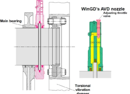
(3) Myeongho Song et al. ; Axial Vibration Damper Modelling Method on the Two Stroke Low Speed Diesel Engine. 양 실린더 간에 오일이 통과하지 못하도록 하여 종진 동 감쇠를 조종할 수 있는 구조로 되어 있다. 이 플레 이트들을 적합하게 겹쳐서 조립하면 AVD의 감쇠를 조정할 수 있다. WinGD사의 AVD 구조는 Fig. 6과 같으며 우측 그림에서 노즐을 이용하여 두 실린더 사 이의 오일 흐름을 조정할 수 있으며 특이한 점은 우측 그림에서 실린더 사이에 사용된 링은 황동으로 제작 되어 수리보수가 불필요한 반영구적이며 시운전시 종 진폭을 체크하여 그 기능을 확인하고 별도로 모니터 링 장치를 설치하지 않는다. Fig. 7은 종진동에 의해서 발생하는 추력변동력을 조정하기 위하여 실린더 간에 오일이 통과할 수 있는 라멜라 플레이트의 두께를 조. 보기도 어려울 수 있다. 유사하게 비틀림진동 댐퍼로 사용되고 있는 실리콘유가 충전된 점성댐퍼의 경우도 제작사에서 점성과 강성을 동시에 고려한 값을 제시 하고 있다. 식 (1)은 이러한 두 영역의 경계를 검토하 여 감쇠와 강성이 복합된 수식이다. 그리고 AVD의 모델링 방법을 점성 비틀림진동댐퍼와 주 저자의 지 금까지 경험을 고려하여 Fig. 8에 보인바와 같이 5가 지로 구분하여 표시하였다. A 경우는 AVD가 작동되 지 않을 경우이며 식 (1)에서 , 는 모두 영인 상태. 정하여 선체진동을 감소시킨 사례이다(3). 이 실험결과 에서 AVD를 순수한 감쇠력만으로 작용하는데 큰 무 리가 있다. 또한 순수한 강성으로 작용하는 디튜터로. Fig. 6 AVD of WinGD Company. Fig. 4 Early design of damper for axial vibration Fig. 7 Hull structure vibration by AVD damping adjustment. Fig. 5 AVD of MAN ES Company.. Fig. 8 AVD modelling methods Trans. Korean Soc. Noise Vib. Eng., 29(6) : 787~793, 2019. 789. ┃.
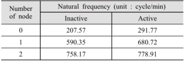
(4) Myeongho Song et al. ; Axial Vibration Damper Modelling Method on the Two Stroke Low Speed Diesel Engine. 이다. B는 가 1인 순수한 감쇠만을 고려한 댐퍼 모 델이고 C는 가 1인 순수한 강성만 고려한 디튜너 모 델이다. 종진동 및 선체진동의 계측자료 그리고 점성. 사에서 제공받았다. C 모델을 기준으로 계산된 고유진동수를 Table 2. 댐퍼의 모델링 기법을 참조하여 AVD도 감쇠와 강성 이 동시에 작용하는 복합된 모델로 모델링할 수 있으 며 D의 경우는( = 0.866, = 0.5) 감쇠에 E의 경우. 동하지 않을 경우 크랭크축의 선단진폭을 보이며 이 실험은 축의 안전과 베어링들의 손상을 고려하여 수 행하기가 곤란하며, AVD의 성능을 항상 모니터링하. 는( = 0.5, = 0.866) 강성에 가까운 모델이다. 여기 서 × 는 감쇠 항이고 × 는 강성 항이며 위상 은 90° 간격이다.. 기 위한 장치가 본선에 설치되어 있다. Fig. 11은 추. . (1). 3. 종진동 댐퍼의 이론 모델에 따른 종진동해석 연구 대상 선박의 추진을 위한 엔진 및 프로펠러의 제원은 Table 1과 같다. 종진동 해석은 자체적으로 개 발된 프로그램을 이용하였고(4), MAN ES에서 추천하 는 모델을 이용 실린더 당 2개의 집중질량계로 분할 하였다. 종 및 비틀림 진동 하모닉 계수는 엔진제작. 에 보인다. Fig. 10은 Fig. 8의 A 모델에서 AVD가 작. Table 1 Specification of the 11G90ME propulsion engine Axial damper Thrust bearing. Torsional damper. Main engine. Fig. 9 Mass spring system for axial vibration. Propeller. Stiffness of thrust (MN/m). 590. Rel. damping (MN/s). 6.0. Weight (kg). 7300. Stiffness of thrust (MN/m). 3153. Tuned type. D360/2/V/M. Diameter (mm). 3600. Outer/Inner inertia (kg․m2). 56 500/4506. Stiffness (MN․m/rad). 210. Relative damping (kN-m/s). 1250. Weight (kg). 31 565. Type. 11G90ME. Cylinder bore×stroke (mm). 900×3260. Power at MCR (kW×r/min). 46 360×75.7. Pmi at full load (bar). 17.11. Nominal torque (kN·m). 5848. Reciprocating mass (kg/cyl.). 15 767. Firing order. 1-5-11-6-2-7-9-4 -3-6-10(uneven). Dia. of crank shaft (mm). 1130. Conn. ratio (r/l). 0.488. No. of cylinder. 11. Weight (ton). 1786. Type. Fixed pitch. Diameter (m). 10.0. No. of blade (ea). 5. Moment of inertia (ton․m2(in water)). 512.2. Weight (ton). 88.46. Table 2 Natural frequencies of axial vibration Number of node. Fig. 10 Axial displacement amplitude at crank shaft free end of modelling method A 790. Trans. Korean Soc. Noise Vib. Eng., 29(6) : 787~793, 2019. ┃. Natural frequency (unit : cycle/min) Inactive. Active. 0. 207.57. 291.77. 1. 590.35. 680.72. 2. 758.17. 778.91.
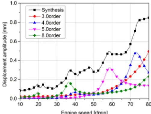
(5) Myeongho Song et al. ; Axial Vibration Damper Modelling Method on the Two Stroke Low Speed Diesel Engine. 력베어링(Fig. 9의 Mass No. 28)의 추력 변동력을 보 이며 60 r/min 이하에서 발생하는 힘은 비틀림진동에. 가 쉽지 않고 중요성도 떨어진 곳이다. 모델 A, B, C 의 해석결과로부터 AVD는 순수한 감쇠 또는 강성. 의해서 기인된 것이며(5,6) 60 r/min 이상에서는 순수. 기능만으로 작용하는 것으로 보기는 어렵다. 이를 보. 한 종진동으로 0절 3차의 공진점이 엔진상용회전수 안에 존재한다. Fig. 12는 Fig. 8의 B 모델인 AVD의 순수한 감쇠. 완하기 위한 모델이 D, E의 모델이며 D 모델은 댐퍼 의 특성이 강하고 E 모델은 디튜너 특성에 가까운 모 델이다. 그리고 Fig. 16, Fig. 17은 Fig. 8의 모델 D, E 에 대한 추력 베어링의 종진폭의 해석결과이며 E 모. 로 가정하여 해석한 진폭으로 4차 성분은 7차 성분보 다 적어 그림 상에 표시가 되지 않았다. Fig. 13에서 도 동일하게 추력변동력을 보이며 4차 성분은 비틀림 진동에 의한 성분만 현저하게 크고 선체진동이 일어 나기 쉬운 60 r/min이상에서는 크지 않다. Fig. 14는 Fig. 8의 C 모델에서 강성만 존재하는 순수한 디튜너 모델로 4, 5차의 피크 점을 보이며 Fig. 15에서 추력 변동력은 4차가 또 다른 피크 점을 70 r/min이상에서 보인다. Fig. 7과 같이 선체진동이 일어날 경우 AVD 의 이러한 감쇠조정과 같은 효과를 확인할 수 있다. 이 실험 대상 선박은 14 000 TEU의 대형 컨테이너선 으로 연돌과 거주구가 분리되어 있는 구조로 엔진이 있는 위치는 바로 연돌에 해당되어 선체진동의 체크. Fig. 13 Thrust variation force at thrust bearing of modelling method B. Fig. 11 Thrust variation force at thrust bearing of modelling method A. Fig. 14 Axial displacement amplitude at crank shaft free end of modelling method C. Fig. 12 Axial displacement amplitude at crank shaft free end of modelling method B. Fig. 15 Thrust variation force at thrust bearing of modelling method C Trans. Korean Soc. Noise Vib. Eng., 29(6) : 787~793, 2019. 791. ┃.
(6) Myeongho Song et al. ; Axial Vibration Damper Modelling Method on the Two Stroke Low Speed Diesel Engine. 델은 종진동 3차 공진영역에서 종진폭이 증가함을 확 인할 수 있다. 또한 이 값에 추력베어링의 강성 값을 곱하면 추력변동력이 된다.. 4. 종진동 실험결과와 비교 크랭크축 선단진폭은 종진동 모니터링 시스템을 이용하였고 크랭크축과 연결된 중간축의 플랜지에서 종진폭을 측정하기 위하여 LVDT를 설치하였으며 전. 로 판단된다. 3차와 4차 성분의 진폭은 해석결과보다 적지만 오히려 디튜너 모델에 가깝고 비틀림진동의 공 진점인 40 r/min에서는 종진폭이 크지 않아 감쇠값이 적게 평가되는 것으로 판단된다. Fig. 20은 중간축에서 측정한 종진폭 결과로 이론 해석상 0절의 진동모드는 추력베어링과 진폭과 같다. 여기서 1차와 2차는 크랭 크축 선단과 유사하게 중간축의 런아웃으로 판단된다 해석상으로 3차와 5차는 크지 않지만 측정결과는 약 간 큰 편이다. 4차는 AVD의 강성 성분이 강한 E 모. 체적인 장비는 Fig. 18과 같이 배치하였다. 그리고 여 기서 얻은 신호는 NI A/D 변환기를 이용하였고 분석 S/W는 자체 개발한 EVAMOS를(7) 이용하였다. 또한 추력변동의 주원인인 비틀림진동을 측정하기 위하여 중간축에 스트레인게이지를 이용한 full bridge를 구 성하여 부착하고 원격 시스템을 이용 비틀림진동을 동시에 측정하였다. Fig. 19는 크랭크축 선단에서 측정 한 종진폭이며 1차와 2차는 주 베어링의 상부 갭에 의 해서 크랭크축이 회전하면서 생기는 런아웃(run-out)으. Fig. 18 Schematic diagram for torsional and axial vibration measurement. Fig. 16 Axial displacement amplitude at thrust bearing of modelling method D. Fig. 19 Axial displacement amplitude measurement at crank shaft free end. Fig. 17 Axial displacement amplitude at thrust bearing of modelling method E. Fig. 20 Axial displacement amplitude measurement at intermediate shaft. 792. Trans. Korean Soc. Noise Vib. Eng., 29(6) : 787~793, 2019. ┃.
(7) Myeongho Song et al. ; Axial Vibration Damper Modelling Method on the Two Stroke Low Speed Diesel Engine. 델의 해석결과인 Fig. 17과 비교하여 비틀림진동의 공진점인 40 r/min에서는 약간 낮지만 60 r/min 이상 에서는 해석결과와 유사하다.. Copenhagen, No. A14, pp. 623~692. (3) Lee, D. C., Choi, J. S. and Kim, U. K., 1994, Dynamic Characteristic of Axial Vibration Damper and. 5. 결 론. its Application for Propulsion Shafting System with Marine Diesel Engine, Proceedings of the ICVE’94, pp. 471~476.. 선박용 주기관으로 사용하는 2행정 저속 디젤엔진 은 크랭크축을 보호하기 AVD를 부착하고 있다. 이 논문은 AVD의 모델링 방법을 연구하였으며 이를 정 리 요약하면 다음과 같다. (1) 종진동의 공진영역에서는 AVD의 감쇠를 강성 으로 전환하여 해석한 디튜너 모델이 적합하였다. 특 히 선체 상부 전후진동의 기진원이 되는 종진동에 의 한 추력베어링의 변동 추력을 추정하기 위해서는 이 모델이 실험결과와 유사하였다. (2) 종진동의 비공진영역에서는 계측된 크랭크축의 선 단 진폭을 검토할 때 AVD의 감쇠 모델이 적합하였다. (3) 비틀림진동에 의한 추력 변동력은 댐퍼 모델과 디튜너 모델 모두 유사하게 동일하였다. 그리고 선박용 2행정 저속 디젤엔진의 실린더 및 유형별 특성에 따라 감쇠와 강성을 특성에 따라 적합하게 조합하여 적용하 는 것이 바람직하며, 좀 더 정확한 해석 자료를 얻기 위해서는 축적된 실선의 측정 자료를 데이터베이스화 하여 AVD 해석 모델을 개발하는 것이 바람직하다.. (4) Song, M. H. and Lee, D. C., 2018, Axial Vibration Analysis Model and Its Vibration Characteristics on the Ultra Long Stroke Low Speed Diesel Engine A Study of Axial Vibration of Two Stroke Low Speed Diesel Engine, Transactions of the Korean Society for Noise and Vibration Engineering, Vol. 28, No. 6, pp. 635~641. (5) Fujii, K. and Tanida, K., 1984, Exciting Forces of Ship Vibration Induced by Torsional and Longitudinal Vibration of Shafting System, ICMES’84. (6) Hylarides, S. and van Gent, W., 1979, Hydrodynamic Reactions to Propeller Vibrations, Schi en Werf, Vol. 46, p. 383. (7) Lee, D. C., Joo, K. S., Nam, T. K., Kim, E. S. and Kim, S. H., 2009, Development of Engine Vibration Analysis and Monitoring System(EVAMOS) for Marine Vessels, Transactions of the Korean Society for Noise and Vibration Engineering, Vol. 19, No. 2, pp. 155~161.. 후 기. Myeongho Song received his M. Eng. from Mokpo Maritime University in 2008. He is now working Ship. 이 연구는 산업통상자원부 소관 산업융합기반구축 사업의 “중소형 선박엔진 및 관련기자재 공인시험인 증센터 구축” 사업의 지원을 받아 수행되었습니다.. Repair Supporting Center. Also he is studying Doctor course at Dynamics Lab. of Mokpo maritime university.. References (1) Jacobsen, S. B. et. al., 1991, Axial Vibrations of Crankshafts of Long-stroke Diesel Engine, and the Control of Their Influence on Crankshaft Strength and Hull Vibration Controls, 19th CIMAC Congress, Florence, No. D61 (2) Gugielmotti, A. and Maciotta, R. 1962, Recherches Experimentales pour L'etude des Vibrations Axiales des Vilebrequins, 1962, 6th CIMAC Congress,. Donchool Lee received his Dr. Eng. from Mechanical Engineering department at Korea Maritime University in 1995. He worked at Hyundai Heavy Industries from 1983 to 1999. He is now a professor of Mokpo National Maritime University.. Trans. Korean Soc. Noise Vib. Eng., 29(6) : 787~793, 2019. 793. ┃.
(8)
수치
+2

관련 문서
Guidelines for the early management of adults with ischemic stroke: a guideline from the American Heart Association/American Stroke Association Stroke Council,
Through the superposition modeling of single hole waveform, I obtained the vibration waveform on the blasting condition changes and conducted dynamic
Generally, in case that we predict the vibration by blasting, we compute it on the basis of the charge weight per delay but in case of shocking
(a) is without vibration condition, (b) is with vibration casting condition... Figure 4.24 Measured proportional constant a as a function of Si content in Al-Si binary
16 and 4 subjects were i ncl uded.In subdi vi si on 3 the frequency spectrums showed short,i rregul ar pattern bel ow 300Hz i s accompani ed by si mul taneous l ong durati
Low-level jet observed date, station, time, and its wind direction and speed at 850hPa in case
It was found that the NO emission decreased significantly at various condition of operation with the 2-stage combustion type diesel engine, but CO and
Many studies using the assumed mode method have been found for the free vibration analysis of stiffened plate with known elastic boundary conditions.. However
