JPNT 3(2), 45-51 (2014)
http://dx.doi.org/10.11003/JPNT.2014.3.2.045
Copyright © The Korean GNSS Society
J PNT Journal of Positioning, Navigation, and Timing
http://www.gnss.or.kr Print ISSN: 2288-8187 Online ISSN: 2289-0866
1. INTRODUCTION
Global Navigation Satellite System (GNSS) is a system that provides position, navigation and time services to users. Representative GNSS is the Global Positioning System (GPS), which was made in the early 1970s for military purposes in the United States. After GPS was made public for civilian purposes, it has been used around the globe due to wide service area and outstanding generality. Currently, it is being developed and operated by Russia, China, and Japan as well as the United States. With the expansion of the application fields of a satellite navigation system due to the development of technology, GPS has become an essential element of national infrastructure in Korea as well as in foreign countries. However, GNSS has the disadvantage of being vulnerable to jamming. In case of jamming, there is a
Jammer Identification Technique based on a Template Matching Method
Mi Hyun Jin
1, Sang-Rae Yeo
1, Heon Ho Choi
1, Chansik Park
2, Sang Jeong Lee
1†1
Department of Electronics Engineering, Chungnam National University, Daejeon 305-764, Korea
2
Department of Electronics Engineering, Chungbuk National University, Cheongju 361-763, Korea
ABSTRACT
GNSS has the disadvantage of being vulnerable to jamming, and thus, the necessity of jamming countermeasure techniques has gradually increased. Jamming countermeasure techniques can be divided into an anti-jamming technique and a jammer localization technique. Depending on the type of a jammer, applicable techniques and performance vary significantly. Using an appropriate jamming countermeasure technique, the effect of jamming on a GNSS receiver can be attenuated, and prompt action is enabled when estimating the location of a jammer. However, if an inappropriate jamming countermeasure technique is used, a GNSS receiver may not operate in the worst case. Therefore, jammer identification is a technique that is essential for proper action. In this study, a technique that identifies a jammer based on template matching was proposed. For template matching, analysis of a received jamming signal is required; and the signal analysis was performed using a spectral correlation function. Based on a simulation, it was shown that the proposed identification of jamming signals was possible at various JNR.
Keywords: spectral correlation, template matching, jammer identification
possibility that confusion occurs in society at large, which leads to national loss. In addition, jamming signals have also developed in complicated and diverse forms (Mitch et al.
2011). Therefore, the necessity of jamming countermeasure techniques to cope with this has gradually increased.
Based on this trend, studies on jamming countermeasure techniques are extensively performed in Korea and in foreign countries at present.
Jamming countermeasure techniques can be broadly divided into an anti-jamming technique and a jammer localization technique. The representative anti-jamming techniques that are applicable to array antennas include the space time adaptive process (STAP) (Godara 2004) and the space frequency adaptive process (SFAP) (Godara 2004);
and the representative jammer localization techniques include the time difference of arrival (TDOA) localization technique (Smith & Abel 1987) and the angle of arrival (AOA) localization technique (Schmidt 1986). Each technique has inherent advantages and disadvantages; and depending on the type of a jammer, applicable techniques and performance vary significantly. If an appropriate Received Apr 09, 2014 Revised May 10, 2014 Accepted May 12, 2014
†
Corresponding Author E-mail: [email protected]
Tel: +82-42-865-3991 Fax: +82-42-823-5436
46 JPNT 3(2), 45-51 (2014)
http://dx.doi.org/10.11003/JPNT.2014.3.2.045
jamming countermeasure technique is used, the effect of jamming on a GNSS receiver is not significant, and prompt action is enabled by finding a correct location in a short time when estimating the location of a jammer. However, if an inappropriate jamming countermeasure technique is used, the performance of the anti-jamming technique deteriorates, and the amount of algorithm calculation could increase beyond necessity. Also, in the worst case, the estimation of jammer location could fail or an incorrect location could be estimated. Thus, jammer identification is a technique that is essential for proper action against jamming. However, despite the importance, there have been relatively few studies on jammer identification techniques compared to those on jamming countermeasure techniques.
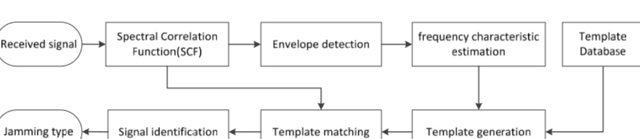
Therefore, in this study, a jammer identification technique was investigated, and a technique that identifies a jammer based on template matching was proposed. Each jamming signal has different spectral auto-correlation. By analyzing this in various aspects, the characteristic of each signal can be drawn. The obtained characteristic was used for generating templates for each jamming signal type. To define the similarity between an incident signal and each template, the Euclidean distance between a normalized spectral correlation result and a template depending on jamming signal type was drawn. Lastly, jammer identification was enabled by defining the jamming type of the received signal using the result of the similarity analysis.
For the jammer identification technique proposed in this study, the performance was analyzed and the validity was verified using a software-based simulator.
2. JAMMING SIGNAL ANALYSIS
For jammer identification, the characteristic of each jamming signal needs to be analyzed and utilized. Thus, application of an appropriate signal analysis technique is required. Diverse signal analysis techniques were examined, and a signal analysis technique appropriate for this study was selected.
2.1 Jamming Signal
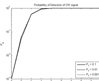
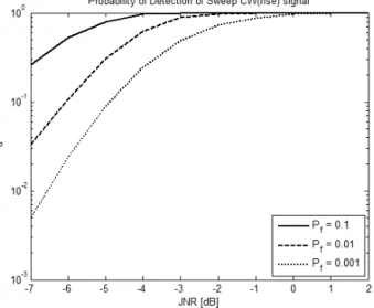
Jamming signals can be broadly divided into a narrowband jamming signal and a wideband jamming signal. To examine the applicability of the identification technique proposed in this study, a narrowband jamming signal (continuous wave (CW) signal) and a wideband jamming signal (sweep CW signal that has the bandwidth
of a GPS signal) were considered as the representative examples, respectively. The model of a CW signal can be expressed as Eq. (1).
on jamming countermeasure techniques are extensively performed in Korea and in foreign countries at present.
Jamming countermeasure techniques can be broadly divided into an anti-jamming technique and a jammer localization technique. The representative anti-jamming techniques that are applicable to array antennas include the space time adaptive process
(STAP
)(Godara 2004) and the space frequency adaptive process (SFAP) (Godara 2004); and the representative jammer localization techniques include the time difference of arrival (TDOA) localization technique (Smith & Abel 1987) and the angle of arrival (AOA) localization technique (Schmidt 1986).
Each technique has inherent advantages and disadvantages; and depending on the type of a jammer, applicable techniques and performance vary significantly. If an appropriate jamming countermeasure technique is used, the effect of jamming on a GNSS receiver is not significant, and prompt action is enabled by finding a correct location in a short time when estimating the location of a jammer. However, if an inappropriate jamming countermeasure technique is used, the performance of the anti-jamming technique deteriorates, and the amount of algorithm calculation could increase beyond necessity. Also, in the worst case, the estimation of jammer location could fail or an incorrect location could be estimated. Thus, jammer identification is a technique that is essential for proper action against jamming. However, despite the importance, there have been relatively few studies on jammer identification techniques compared to those on jamming countermeasure techniques.
Therefore, in this study, a jammer identification technique was investigated, and a technique that identifies a jammer based on template matching was proposed. Each jamming signal has different spectral auto-correlation. By analyzing this in various aspects, the characteristic of each signal can be drawn. The obtained characteristic was used for generating templates for each jamming signal type. To define the similarity between an incident signal and each template, the Euclidean distance between a normalized spectral correlation result and a template depending on jamming signal type was drawn. Lastly, jammer identification was enabled by defining the jamming type of the received signal using the result of the similarity analysis. For the jammer identification technique proposed in this study, the performance was analyzed and the validity was verified using a software-based simulator.
2. JAMMING SIGNAL ANALYSIS
For jammer identification, the characteristic of each jamming signal needs to be analyzed and utilized. Thus, application of an appropriate signal analysis technique is required. Diverse signal analysis techniques were examined, and a signal analysis technique appropriate for this study was selected.
2.1 Jamming Signal
Jamming signals can be broadly divided into a narrowband jamming signal and a wideband jamming signal. To examine the applicability of the identification technique proposed in this study, a narrowband jamming signal (continuous wave (CW) signal) and a wideband jamming signal (sweep CW signal that has the bandwidth of a GPS signal) were considered as the representative examples, respectively. The model of a CW signal can be expressed as Eq. (1).
( ) sin( )
cw c
x t k t (1)
where where k is the amplitude of the signal, and
cis the frequency of the signal. On the other hand, the model of a sweep CW signal can be expressed as Eq. (2).
( ) sin( ( ) )
sw c sw
x t k f t dt (2)
where f t
sw( ) is the frequency change information of the sweep CW signal. In general, f t
sw( ) can be modeled as shown in Eq. (3).
,
, , ,
( ) , ( )
( ) ,
sw s u sw u
sw s
sw s d sw u sw u sw d
s
f t T k n t n T
f t f t T k f n T t n T T f
(3)
where f
sis the sampling frequency, T
sis the period of sampling, and k
uand k
dare the amount of frequency change for the rising frequency shift section and the falling frequency shift section, respectively. For a sweep CW signal, frequency shifts with time, and the characteristic of the signal is determined by the frequency change information depending on time. The amount of frequency change determines the frequency bandwidth of the sweep CW signal. In this study, this value was set to be identical to the bandwidth of a GPS signal. Also, depending on whether it is rising or falling, the characteristic of the signal changes; and depending on this, whether it can be removed changes. Therefore, three kinds of cases were considered: a sweep CW (rise) signal that has rising frequency, a sweep CW (fall) signal that has falling frequency, and a sweep CW (tri) signal that has the two changing trends at the same time.
2.2 Spectral Correlation Function (SCF)
For a signal analysis technique in a frequency domain, there are various techniques, and the representative method is the Fourier transform. However, this technique shows only the frequency component of a signal, and the changes in signal characteristics depending on time cannot be examined (Kamen & Heck 2000). Diverse signals can be regarded as a jamming signal, and the characteristics of several jamming signals could change with time. Accordingly, analyzing a jamming signal using only the Fourier transform would not be stable. Therefore, in this study, SCF was used for the analysis of signals.
Spectral correlation function (SCF) can analyze signal characteristics including
cyclostationary characteristics. When the average and auto-correlation value of a specific target signal, x t ( ) , show periodic characteristics, it is said that x t ( ) has cyclostationary characteristics.
Eqs. (4) and (5) express the cyclostationary characteristics of the signal, x t ( ) (Gardner 1986).
x x
m t T m t
(4)
, ,
x x
R t T u T R t u
(5)
is the amplitude of the signal, and where k is the amplitude of the signal, and
cis the frequency of the signal. On the other hand, the model of a sweep CW signal can be expressed as Eq. (2).
( ) sin( ( ) )
sw c sw
x t k f t dt (2)
where f t
sw( ) is the frequency change information of the sweep CW signal. In general, f t
sw( ) can be modeled as shown in Eq. (3).
,
, , ,
( ) , ( )
( ) ,
sw s u sw u
s sw
sw s d sw u sw u sw d
s
f t T k n t n T
f t f
f t T k n T t n T T f
(3)
where f
sis the sampling frequency, T
sis the period of sampling, and k
uand k
dare the amount of frequency change for the rising frequency shift section and the falling frequency shift section, respectively. For a sweep CW signal, frequency shifts with time, and the characteristic of the signal is determined by the frequency change information depending on time. The amount of frequency change determines the frequency bandwidth of the sweep CW signal. In this study, this value was set to be identical to the bandwidth of a GPS signal. Also, depending on whether it is rising or falling, the characteristic of the signal changes; and depending on this, whether it can be removed changes. Therefore, three kinds of cases were considered: a sweep CW (rise) signal that has rising frequency, a sweep CW (fall) signal that has falling frequency, and a sweep CW (tri) signal that has the two changing trends at the same time.
2.2 Spectral Correlation Function (SCF)
For a signal analysis technique in a frequency domain, there are various techniques, and the representative method is the Fourier transform. However, this technique shows only the frequency component of a signal, and the changes in signal characteristics depending on time cannot be examined (Kamen & Heck 2000). Diverse signals can be regarded as a jamming signal, and the characteristics of several jamming signals could change with time. Accordingly, analyzing a jamming signal using only the Fourier transform would not be stable. Therefore, in this study, SCF was used for the analysis of signals.
Spectral correlation function (SCF) can analyze signal characteristics including
cyclostationary characteristics. When the average and auto-correlation value of a specific target signal, x t ( ) , show periodic characteristics, it is said that x t ( ) has cyclostationary characteristics.
Eqs. (4) and (5) express the cyclostationary characteristics of the signal, x t ( ) (Gardner 1986).
x x
m t T m t
(4)
, ,
x x
R t T u T R t u
(5) is the
frequency of the signal. On the other hand, the model of a sweep CW signal can be expressed as Eq. (2).
where k is the amplitude of the signal, and
cis the frequency of the signal. On the other hand, the model of a sweep CW signal can be expressed as Eq. (2).
( ) sin( ( ) )
sw c sw
x t k f t dt (2)
where f t
sw( ) is the frequency change information of the sweep CW signal. In general, f t
sw( ) can be modeled as shown in Eq. (3).
,
, , ,
( ) , ( )
( ) ,
sw s u sw u
s sw
sw s d sw u sw u sw d
s
f t T k n t n T
f t f
f t T k n T t n T T f
(3)
where f
sis the sampling frequency, T
sis the period of sampling, and k
uand k
dare the amount of frequency change for the rising frequency shift section and the falling frequency shift section, respectively. For a sweep CW signal, frequency shifts with time, and the characteristic of the signal is determined by the frequency change information depending on time. The amount of frequency change determines the frequency bandwidth of the sweep CW signal. In this study, this value was set to be identical to the bandwidth of a GPS signal. Also, depending on whether it is rising or falling, the characteristic of the signal changes; and depending on this, whether it can be removed changes. Therefore, three kinds of cases were considered: a sweep CW (rise) signal that has rising frequency, a sweep CW (fall) signal that has falling frequency, and a sweep CW (tri) signal that has the two changing trends at the same time.
2.2 Spectral Correlation Function (SCF)
For a signal analysis technique in a frequency domain, there are various techniques, and the representative method is the Fourier transform. However, this technique shows only the frequency component of a signal, and the changes in signal characteristics depending on time cannot be examined (Kamen & Heck 2000). Diverse signals can be regarded as a jamming signal, and the characteristics of several jamming signals could change with time. Accordingly, analyzing a jamming signal using only the Fourier transform would not be stable. Therefore, in this study, SCF was used for the analysis of signals.
Spectral correlation function (SCF) can analyze signal characteristics including
cyclostationary characteristics. When the average and auto-correlation value of a specific target signal, x t ( ) , show periodic characteristics, it is said that x t ( ) has cyclostationary characteristics.
Eqs. (4) and (5) express the cyclostationary characteristics of the signal, x t ( ) (Gardner 1986).
x x
m t T m t
(4)
, ,
x x
R t T u T R t u
(5) where k is the amplitude of the signal, and
cis the frequency of the signal. On the other hand,
the model of a sweep CW signal can be expressed as Eq. (2).
( ) sin( ( ) )
sw c sw
x t k f t dt (2)
where f t
sw( ) is the frequency change information of the sweep CW signal. In general, f t
sw( ) can be modeled as shown in Eq. (3).
,
, , ,
( ) , ( )
( ) ,
sw s u sw u
s sw
sw s d sw u sw u sw d
s
f t T k n t n T
f t f
f t T k n T t n T T f
(3)
where f
sis the sampling frequency, T
sis the period of sampling, and k
uand k
dare the amount of frequency change for the rising frequency shift section and the falling frequency shift section, respectively. For a sweep CW signal, frequency shifts with time, and the characteristic of the signal is determined by the frequency change information depending on time. The amount of frequency change determines the frequency bandwidth of the sweep CW signal. In this study, this value was set to be identical to the bandwidth of a GPS signal. Also, depending on whether it is rising or falling, the characteristic of the signal changes; and depending on this, whether it can be removed changes. Therefore, three kinds of cases were considered: a sweep CW (rise) signal that has rising frequency, a sweep CW (fall) signal that has falling frequency, and a sweep CW (tri) signal that has the two changing trends at the same time.
2.2 Spectral Correlation Function (SCF)
For a signal analysis technique in a frequency domain, there are various techniques, and the representative method is the Fourier transform. However, this technique shows only the frequency component of a signal, and the changes in signal characteristics depending on time cannot be examined (Kamen & Heck 2000). Diverse signals can be regarded as a jamming signal, and the characteristics of several jamming signals could change with time. Accordingly, analyzing a jamming signal using only the Fourier transform would not be stable. Therefore, in this study, SCF was used for the analysis of signals.
Spectral correlation function (SCF) can analyze signal characteristics including
cyclostationary characteristics. When the average and auto-correlation value of a specific target signal, x t ( ) , show periodic characteristics, it is said that x t ( ) has cyclostationary characteristics.
Eqs. (4) and (5) express the cyclostationary characteristics of the signal, x t ( ) (Gardner 1986).
x x
m t T m t
(4)
, ,
x x
R t T u T R t u
(5) where
where k is the amplitude of the signal, and
cis the frequency of the signal. On the other hand, the model of a sweep CW signal can be expressed as Eq. (2).
( ) sin( ( ) )
sw c sw
x t k f t dt (2)
where f t
sw( ) is the frequency change information of the sweep CW signal. In general, f t
sw( ) can be modeled as shown in Eq. (3).
,
, , ,
( ) , ( )
( ) ,
sw s u sw u
s sw
sw s d sw u sw u sw d
s
f t T k n t n T
f t f
f t T k n T t n T T f
(3)
where f
sis the sampling frequency, T
sis the period of sampling, and k
uand k
dare the amount of frequency change for the rising frequency shift section and the falling frequency shift section, respectively. For a sweep CW signal, frequency shifts with time, and the characteristic of the signal is determined by the frequency change information depending on time. The amount of frequency change determines the frequency bandwidth of the sweep CW signal. In this study, this value was set to be identical to the bandwidth of a GPS signal. Also, depending on whether it is rising or falling, the characteristic of the signal changes; and depending on this, whether it can be removed changes. Therefore, three kinds of cases were considered: a sweep CW (rise) signal that has rising frequency, a sweep CW (fall) signal that has falling frequency, and a sweep CW (tri) signal that has the two changing trends at the same time.
2.2 Spectral Correlation Function (SCF)
For a signal analysis technique in a frequency domain, there are various techniques, and the representative method is the Fourier transform. However, this technique shows only the frequency component of a signal, and the changes in signal characteristics depending on time cannot be examined (Kamen & Heck 2000). Diverse signals can be regarded as a jamming signal, and the characteristics of several jamming signals could change with time. Accordingly, analyzing a jamming signal using only the Fourier transform would not be stable. Therefore, in this study, SCF was used for the analysis of signals.
Spectral correlation function (SCF) can analyze signal characteristics including
cyclostationary characteristics. When the average and auto-correlation value of a specific target signal, x t ( ) , show periodic characteristics, it is said that x t ( ) has cyclostationary characteristics.
Eqs. (4) and (5) express the cyclostationary characteristics of the signal, x t ( ) (Gardner 1986).
x x
m t T m t
(4)
, ,
x x
R t T u T R t u
(5) is the frequency change information of the
sweep CW signal. In general, where k is the amplitude of the signal, and
cis the frequency of the signal. On the other hand, the model of a sweep CW signal can be expressed as Eq. (2).
( ) sin( ( ) )
sw c sw
x t k f t dt (2)
where f t
sw( ) is the frequency change information of the sweep CW signal. In general, f t
sw( ) can be modeled as shown in Eq. (3).
,
, , ,
( ) , ( )
( ) ,
sw s u sw u
sw s
sw s d sw u sw u sw d
s
f t T k n t n T
f t f t T k f n T t n T T f
(3)
where f
sis the sampling frequency, T
sis the period of sampling, and k
uand k
dare the amount of frequency change for the rising frequency shift section and the falling frequency shift section, respectively. For a sweep CW signal, frequency shifts with time, and the characteristic of the signal is determined by the frequency change information depending on time. The amount of frequency change determines the frequency bandwidth of the sweep CW signal. In this study, this value was set to be identical to the bandwidth of a GPS signal. Also, depending on whether it is rising or falling, the characteristic of the signal changes; and depending on this, whether it can be removed changes. Therefore, three kinds of cases were considered: a sweep CW (rise) signal that has rising frequency, a sweep CW (fall) signal that has falling frequency, and a sweep CW (tri) signal that has the two changing trends at the same time.
2.2 Spectral Correlation Function (SCF)
For a signal analysis technique in a frequency domain, there are various techniques, and the representative method is the Fourier transform. However, this technique shows only the frequency component of a signal, and the changes in signal characteristics depending on time cannot be examined (Kamen & Heck 2000). Diverse signals can be regarded as a jamming signal, and the characteristics of several jamming signals could change with time. Accordingly, analyzing a jamming signal using only the Fourier transform would not be stable. Therefore, in this study, SCF was used for the analysis of signals.
Spectral correlation function (SCF) can analyze signal characteristics including
cyclostationary characteristics. When the average and auto-correlation value of a specific target signal, x t ( ) , show periodic characteristics, it is said that x t ( ) has cyclostationary characteristics.
Eqs. (4) and (5) express the cyclostationary characteristics of the signal, x t ( ) (Gardner 1986).
x x
m t T m t
(4)
, ,
x x
R t T u T R t u
(5)
can be modeled as shown in Eq. (3).
where k is the amplitude of the signal, and
cis the frequency of the signal. On the other hand, the model of a sweep CW signal can be expressed as Eq. (2).
( ) sin( ( ) )
sw c sw
x t k f t dt (2)
where f t
sw( ) is the frequency change information of the sweep CW signal. In general, f t
sw( ) can be modeled as shown in Eq. (3).
,
, , ,
( ) , ( )
( ) ,
sw s u sw u
s sw
sw s d sw u sw u sw d
s
f t T k n t n T
f t f
f t T k n T t n T T f
(3)
where f
sis the sampling frequency, T
sis the period of sampling, and k
uand k
dare the amount of frequency change for the rising frequency shift section and the falling frequency shift section, respectively. For a sweep CW signal, frequency shifts with time, and the characteristic of the signal is determined by the frequency change information depending on time. The amount of frequency change determines the frequency bandwidth of the sweep CW signal. In this study, this value was set to be identical to the bandwidth of a GPS signal. Also, depending on whether it is rising or falling, the characteristic of the signal changes; and depending on this, whether it can be removed changes. Therefore, three kinds of cases were considered: a sweep CW (rise) signal that has rising frequency, a sweep CW (fall) signal that has falling frequency, and a sweep CW (tri) signal that has the two changing trends at the same time.
2.2 Spectral Correlation Function (SCF)
For a signal analysis technique in a frequency domain, there are various techniques, and the representative method is the Fourier transform. However, this technique shows only the frequency component of a signal, and the changes in signal characteristics depending on time cannot be examined (Kamen & Heck 2000). Diverse signals can be regarded as a jamming signal, and the characteristics of several jamming signals could change with time. Accordingly, analyzing a jamming signal using only the Fourier transform would not be stable. Therefore, in this study, SCF was used for the analysis of signals.
Spectral correlation function (SCF) can analyze signal characteristics including
cyclostationary characteristics. When the average and auto-correlation value of a specific target signal, x t ( ) , show periodic characteristics, it is said that x t ( ) has cyclostationary characteristics.
Eqs. (4) and (5) express the cyclostationary characteristics of the signal, x t ( ) (Gardner 1986).
x x
m t T m t
(4)
, ,
x x
R t T u T R t u
(5) where k is the amplitude of the signal, and
cis the frequency of the signal. On the other hand,
the model of a sweep CW signal can be expressed as Eq. (2).
( ) sin( ( ) )
sw c sw
x t k f t dt (2)
where f t
sw( ) is the frequency change information of the sweep CW signal. In general, f t
sw( ) can be modeled as shown in Eq. (3).
,
, , ,
( ) , ( )
( ) ,
sw s u sw u
s sw
sw s d sw u sw u sw d
s
f t T k n t n T
f t f
f t T k n T t n T T f
(3)
where f
sis the sampling frequency, T
sis the period of sampling, and k
uand k
dare the amount of frequency change for the rising frequency shift section and the falling frequency shift section, respectively. For a sweep CW signal, frequency shifts with time, and the characteristic of the signal is determined by the frequency change information depending on time. The amount of frequency change determines the frequency bandwidth of the sweep CW signal. In this study, this value was set to be identical to the bandwidth of a GPS signal. Also, depending on whether it is rising or falling, the characteristic of the signal changes; and depending on this, whether it can be removed changes. Therefore, three kinds of cases were considered: a sweep CW (rise) signal that has rising frequency, a sweep CW (fall) signal that has falling frequency, and a sweep CW (tri) signal that has the two changing trends at the same time.
2.2 Spectral Correlation Function (SCF)
For a signal analysis technique in a frequency domain, there are various techniques, and the representative method is the Fourier transform. However, this technique shows only the frequency component of a signal, and the changes in signal characteristics depending on time cannot be examined (Kamen & Heck 2000). Diverse signals can be regarded as a jamming signal, and the characteristics of several jamming signals could change with time. Accordingly, analyzing a jamming signal using only the Fourier transform would not be stable. Therefore, in this study, SCF was used for the analysis of signals.
Spectral correlation function (SCF) can analyze signal characteristics including
cyclostationary characteristics. When the average and auto-correlation value of a specific target signal, x t ( ) , show periodic characteristics, it is said that x t ( ) has cyclostationary characteristics.
Eqs. (4) and (5) express the cyclostationary characteristics of the signal, x t ( ) (Gardner 1986).
x x
m t T m t
(4)
, ,
x x
R t T u T R t u
(5) where
where k is the amplitude of the signal, and
cis the frequency of the signal. On the other hand, the model of a sweep CW signal can be expressed as Eq. (2).
( ) sin( ( ) )
sw c sw
x t k f t dt (2)
where f t
sw( ) is the frequency change information of the sweep CW signal. In general, f t
sw( ) can be modeled as shown in Eq. (3).
,
, , ,
( ) , ( )
( ) ,
sw s u sw u
s sw
sw s d sw u sw u sw d
s
f t T k n t n T
f t f
f t T k n T t n T T f
(3)
where f
sis the sampling frequency, T
sis the period of sampling, and k
uand k
dare the amount of frequency change for the rising frequency shift section and the falling frequency shift section, respectively. For a sweep CW signal, frequency shifts with time, and the characteristic of the signal is determined by the frequency change information depending on time. The amount of frequency change determines the frequency bandwidth of the sweep CW signal. In this study, this value was set to be identical to the bandwidth of a GPS signal. Also, depending on whether it is rising or falling, the characteristic of the signal changes; and depending on this, whether it can be removed changes. Therefore, three kinds of cases were considered: a sweep CW (rise) signal that has rising frequency, a sweep CW (fall) signal that has falling frequency, and a sweep CW (tri) signal that has the two changing trends at the same time.
2.2 Spectral Correlation Function (SCF)
For a signal analysis technique in a frequency domain, there are various techniques, and the representative method is the Fourier transform. However, this technique shows only the frequency component of a signal, and the changes in signal characteristics depending on time cannot be examined (Kamen & Heck 2000). Diverse signals can be regarded as a jamming signal, and the characteristics of several jamming signals could change with time. Accordingly, analyzing a jamming signal using only the Fourier transform would not be stable. Therefore, in this study, SCF was used for the analysis of signals.
Spectral correlation function (SCF) can analyze signal characteristics including
cyclostationary characteristics. When the average and auto-correlation value of a specific target signal, x t ( ) , show periodic characteristics, it is said that x t ( ) has cyclostationary characteristics.
Eqs. (4) and (5) express the cyclostationary characteristics of the signal, x t ( ) (Gardner 1986).
x x
m t T m t
(4)
, ,
x x
R t T u T R t u
(5) is the sampling frequency,
where k is the amplitude of the signal, and
cis the frequency of the signal. On the other hand, the model of a sweep CW signal can be expressed as Eq. (2).
( ) sin( ( ) )
sw c sw
x t k f t dt (2)
where f t
sw( ) is the frequency change information of the sweep CW signal. In general, f t
sw( ) can be modeled as shown in Eq. (3).
,
, , ,
( ) , ( )
( ) ,
sw s u sw u
s sw
sw s d sw u sw u sw d
s
f t T k n t n T
f t f
f t T k n T t n T T f
(3)
where f
sis the sampling frequency, T
sis the period of sampling, and k
uand k
dare the amount of frequency change for the rising frequency shift section and the falling frequency shift section, respectively. For a sweep CW signal, frequency shifts with time, and the characteristic of the signal is determined by the frequency change information depending on time. The amount of frequency change determines the frequency bandwidth of the sweep CW signal. In this study, this value was set to be identical to the bandwidth of a GPS signal. Also, depending on whether it is rising or falling, the characteristic of the signal changes; and depending on this, whether it can be removed changes. Therefore, three kinds of cases were considered: a sweep CW (rise) signal that has rising frequency, a sweep CW (fall) signal that has falling frequency, and a sweep CW (tri) signal that has the two changing trends at the same time.
2.2 Spectral Correlation Function (SCF)
For a signal analysis technique in a frequency domain, there are various techniques, and the representative method is the Fourier transform. However, this technique shows only the frequency component of a signal, and the changes in signal characteristics depending on time cannot be examined (Kamen & Heck 2000). Diverse signals can be regarded as a jamming signal, and the characteristics of several jamming signals could change with time. Accordingly, analyzing a jamming signal using only the Fourier transform would not be stable. Therefore, in this study, SCF was used for the analysis of signals.
Spectral correlation function (SCF) can analyze signal characteristics including
cyclostationary characteristics. When the average and auto-correlation value of a specific target signal, x t ( ) , show periodic characteristics, it is said that x t ( ) has cyclostationary characteristics.
Eqs. (4) and (5) express the cyclostationary characteristics of the signal, x t ( ) (Gardner 1986).
x x
m t T m t
(4)
, ,
x x
R t T u T R t u
(5) is the period of
sampling, and
where k is the amplitude of the signal, and
cis the frequency of the signal. On the other hand, the model of a sweep CW signal can be expressed as Eq. (2).
( ) sin( ( ) )
sw c sw
x t k f t dt (2)
where f t
sw( ) is the frequency change information of the sweep CW signal. In general, f t
sw( ) can be modeled as shown in Eq. (3).
,
, , ,
( ) , ( )
( ) ,
sw s u sw u
s
sw d
sw s sw u sw u sw d
s
f t T k n t n T
f t f
f t T k n T t n T T f
(3)
where f
sis the sampling frequency, T
sis the period of sampling, and k
uand k
dare the amount of frequency change for the rising frequency shift section and the falling frequency shift section, respectively. For a sweep CW signal, frequency shifts with time, and the characteristic of the signal is determined by the frequency change information depending on time. The amount of frequency change determines the frequency bandwidth of the sweep CW signal. In this study, this value was set to be identical to the bandwidth of a GPS signal. Also, depending on whether it is rising or falling, the characteristic of the signal changes; and depending on this, whether it can be removed changes. Therefore, three kinds of cases were considered: a sweep CW (rise) signal that has rising frequency, a sweep CW (fall) signal that has falling frequency, and a sweep CW (tri) signal that has the two changing trends at the same time.
2.2 Spectral Correlation Function (SCF)
For a signal analysis technique in a frequency domain, there are various techniques, and the representative method is the Fourier transform. However, this technique shows only the frequency component of a signal, and the changes in signal characteristics depending on time cannot be examined (Kamen & Heck 2000). Diverse signals can be regarded as a jamming signal, and the characteristics of several jamming signals could change with time. Accordingly, analyzing a jamming signal using only the Fourier transform would not be stable. Therefore, in this study, SCF was used for the analysis of signals.
Spectral correlation function (SCF) can analyze signal characteristics including
cyclostationary characteristics. When the average and auto-correlation value of a specific target signal, x t ( ) , show periodic characteristics, it is said that x t ( ) has cyclostationary characteristics.
Eqs. (4) and (5) express the cyclostationary characteristics of the signal, x t ( ) (Gardner 1986).
x x
m t T m t
(4)
, ,
x x
R t T u T R t u
(5) and
where k is the amplitude of the signal, and
cis the frequency of the signal. On the other hand, the model of a sweep CW signal can be expressed as Eq. (2).
( ) sin( ( ) )
sw c sw
x t k f t dt (2)
where f t
sw( ) is the frequency change information of the sweep CW signal. In general, f t
sw( ) can be modeled as shown in Eq. (3).
,
, , ,
( ) , ( )
( ) ,
sw s u sw u
s
sw d
sw s sw u sw u sw d
s
f t T k n t n T
f t f
f t T k n T t n T T f
(3)
where f
sis the sampling frequency, T
sis the period of sampling, and k
uand k
dare the amount of frequency change for the rising frequency shift section and the falling frequency shift section, respectively. For a sweep CW signal, frequency shifts with time, and the characteristic of the signal is determined by the frequency change information depending on time. The amount of frequency change determines the frequency bandwidth of the sweep CW signal. In this study, this value was set to be identical to the bandwidth of a GPS signal. Also, depending on whether it is rising or falling, the characteristic of the signal changes; and depending on this, whether it can be removed changes. Therefore, three kinds of cases were considered: a sweep CW (rise) signal that has rising frequency, a sweep CW (fall) signal that has falling frequency, and a sweep CW (tri) signal that has the two changing trends at the same time.
2.2 Spectral Correlation Function (SCF)
For a signal analysis technique in a frequency domain, there are various techniques, and the representative method is the Fourier transform. However, this technique shows only the frequency component of a signal, and the changes in signal characteristics depending on time cannot be examined (Kamen & Heck 2000). Diverse signals can be regarded as a jamming signal, and the characteristics of several jamming signals could change with time. Accordingly, analyzing a jamming signal using only the Fourier transform would not be stable. Therefore, in this study, SCF was used for the analysis of signals.
Spectral correlation function (SCF) can analyze signal characteristics including
cyclostationary characteristics. When the average and auto-correlation value of a specific target signal, x t ( ) , show periodic characteristics, it is said that x t ( ) has cyclostationary characteristics.
Eqs. (4) and (5) express the cyclostationary characteristics of the signal, x t ( ) (Gardner 1986).
x x
m t T m t
(4)
, ,
x x