Unified Motion and Force Control of JS-10 Robot Manipulator Based on Operational Space and 3D CAD
작업공간과 3D CAD를 기반으로 하는 JS-10 매니플레이터의 운동과 힘의 통합제어
D. S. Ahn*†and V. P. Nguyen**
안두성*†․NGUYEN VAN PHUC**
(received 12 January 2012, revised 20 April 2012, accepted 16 June 2012)
Key Words:작업공간(Operational Space), 운동과 힘의 통합제어(Unified Motion and Force Control), 매니플레 이터(Manipulator), 3차원 캐드(3D CAD)
Abstract:본 논문은 작업공간상에서 로봇 운동과 힘의 통합제어를 구현할 수 있는 플랫폼의 구현에 초점을 두고 있다. 조립 또는 디버링 같은 접촉작업에서의 매니플레이터 효율성 제고나 친 인간 환경에서의 휴머노 이드 로봇의 안정성을 위해서는 종래의 PID 제어나 관절공간상에서의 CTM(Computed Torque Method) 제어 보다는 작업공간상에서의 운동과 힘의 통합제어를 실시해야 한다. 이것을 위해서는 작업공간상에서의 엔드 이펙트(end-effector, E-E)에 대한 동역학식과 자코비안(jacobian)을 도출해야 하며 이를 위해서는 각종 동적파 라미터의 정확한 동정이 중요하다. 본 논문에서는 3D CAD 모델링, MATLAB, 동역학 시뮬레이터를 활용하 여 로봇 모델링, 동역학식과 동적 파라미터 추출, 운동과 힘의 실시간 통합제어 시뮬레이션등을 쉽고 일관 되게 진행할 수 있는 플랫폼을 구현하였고 적용예로써 JS-10로봇을 택해서 그 효용성을 입증하였다.
*안두성(교신저자) : 부경대학교 기계자동차공학과 E-mail : [email protected], Tel : 051-629-6154
**V. P. Nguyen : 부경대학교 대학원
*D. S. Ahn(corresponding author) : Department of Mechanical
& Automotive Engineering, Pukyong National University.
E-mail : [email protected], Tel : 051-629-6154
**V. P. Nguyen : Department of Mechanical & Automotive Engineering, Pukyong National University.
1. Introduction
In industrial robot manipulators, PID control is usually used. This control method is adequate for simple and imprecise tasks but severely inadequate for fast and precise task. This problem is due that the manipulator dynamics is highly nonlinear with strong couplings between joints. To deal with this problem, model based controllers that use a mathematical dynamic model of the manipulator to explicitly compensate the coupling terms, are implemented. The most common strategy of model based control is CTM performed on joint space1). This method has been the basis for the dynamic control of manipulators. However, task specification
for motion and contact forces, dynamics, and force sensing feedback are closely linked to the E-E in the operational space.
The necessity of operational space control is increasingly demanding for tasks that involve combined motion and contact forces of the E-E required in both industrial manipulators and humanoid robots2). This method implies the Jacobian matrix calculus, its inverse and derivative, that can cause complicated computation or singularity. Nevertheless, the formulation of the control law directly on the operational space have some advantages: first, control performance becomes better in tracking tasks that accompany with important changes on the inertia matrix or
disturbance rejection and second, this approach becomes necessary when the problem of controlling interaction between the manipulator and the environment is involved. Obviously, the operational space dynamic model which describes the dynamic interaction between the E-E motions is basic requirements for the analysis and design of high performance robot control.
Since over the past few years 3D CAD packages are becoming more powerful and accessible, 3D CAD-based solutions related to robotics have been common. But a variety of research has been mainly conducted in the field of CAD-based planning and programming3). Very few studies so far deal with CAD-based control4). For the formulation of operational space dynamic model, many parameters such as inertia tensor , first moment of inertia, mass etc. must be identified. Once CAD model of a robot is constructed, the procedure of the parameter identification can be automated with the help 3D CAD. This means that the effect the design change of a robot on the control can be checked easily.
Then the simulation model of a robot constructed by 3D CAD such as Solidworks or 3D MAX is implemented in real-time dynamic simulation environment. This paper focuses on the development of robotic platform which can do 3D modeling, parameter identification, and real-time simulation of unified motion and force control consistently.
This paper is organized as follows. Section 2 reviews the formulation for the unified motion and force control based on Operational Space. In Section 3, Taking industrial manipulator JS-10 as a case example, the overall scheme of our proposed platform is explained. Parameter identification of JS-10 and symbolic generation of dynamic equations are presented. Section 4 shows real-time simulation that implemented with unified motion and force control to verify the effectiveness of our proposed platform. Finally, conclusions and future work directions are discussed in Section 5.
2. Operational space control of JS-10
The operational space formulation provides a natural framework to address the problem of motion and force control in an integrated manner, allowing the development of unified approach for the control of E-E motions and contact forces6~8). In constrained motion operations, the E-E is subjected to a set of geometric constraints which restrict its freedom of motion. The description of a fine motion task involves specifications of the forces and moments that must be applied at the geometric constraints, and specifications of the E-E motion freedom directions.
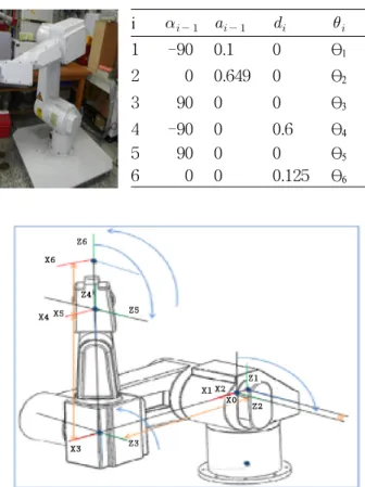
The kinematic relationship between a pair of adjacent links i-1 and i connected through a one-degree-of-freedom joint i can be completely determined by Denavit-Hartenberg parameters5). The coordinate frame attachments and the Denavit-Hartenberg parameters of KAWASAKI robot JS-10 are presented in Fig. 1
2.1 Jacobian of JS10
The manipulator Jacobian
is given by
(1)
where and are 3xn matrices.
The Jacobian matrix can be directly obtained by differentiating the position vector , which locates the center of-mass of link i with respect to the manipulator base,
(2)
The matrix is given by
(3)
i
1 -90 0.1 0 θ1
2 0 0.649 0 θ2
3 90 0 0 θ3
4 -90 0 0.6 θ4
5 90 0 0 θ5
6 0 0 0.125 θ6
Fig. 1 The JS-10 Arm with attached coordinate frames and D-H parameters
2.2 Unified Motion and force control
The operational space force applied at the E-E can be expressed as6)
(4) The vector represents the contact forces acting at the E-E. The unified approach for E-E dynamic decoupling, motion and active force control is achieved by selecting the control structure.
for (5) where,
(6)
for for (7) The operational space control can be compared with computed-torque control in joint space, which is described as follows
(8)
where is joint space kinetic energy matrix,
is the centrifugal and Coriolis forces, and is the gravity compensation vector in joint space.
These dynamic parameters can be translated into task space for use in (6) and (7) by:
(9)
(10)
(11) The “ ^” above the parameter represents our estimate of actual dynamic parameters
and . The vector
and for represent the inputs to the decoupled system. The required force is computed from the required acceleration
.7)
(12)
for (13)
The generalized joint forces required to produce the operational forces are
(14)
Fig. 2 Unified motion and force architecture
The unified motion and force control system is illustrated in Fig. 2
3. Parameter identification of JS-10
The goal in this section is to develop modeling and identification techniques for JS-10 Kawasaki industrial robot. In order to reconstruct 3D CAD modeling, all the dimensions of each rigid links were measured based on our lab robot. These parameters were used to created the modeling of robot. then we carried out the mass and moment of inertia of individual links of robot arm.
First, the simulation 3D solid model is designed by 3D CAD tool such as Solidworks or 3D Studio MAX. Then, we applied mass properties function of Solidworks in order to obtained the robot parameter identification. This function provides accurate parameter estimates that are suitable for realistic robot
(a) JS-10 Kawasaki (b) 3D Solid Model
(c) Symbolic Generation (d) Apply Dynamic Parameters
(e) Control Algorithms (f) Real-time Simulation Fig. 3 Procedure of 3D modeling
simulations, provided that the model structure is correct and all degrees of freedom are known accurately.
Second, the 3D CAD modeling of JS-10 robot is put into the real time dynamic simulator, SimStudio29). The control algorithmsare written in C++ language. The scheme of real time simulation of 3D CAD modeling is illustrated in Fig. 3.
3.1 Dynamic model of JS-10 arm
The mechanical manipulator arm of this robot consists of stiff and lightweight robot links that are interconnected by means of six revolute joints. In the dynamical analysis, forces and torques are related to the robot’s position, velocity and acceleration by means of the equations of motion of (8).
The joint space centrifugal and Coriolis force vector of (8) can be developed in the form
(15) where and are the vectors characterizing centrifugal and Coriolis forces respectively.
The symbols and are the vectors of velocity product and squared velocities, respectively. The extended form of the above symbolic expressions is given
(16)
(17) The procedure used to derive the dynamic model of the manipulator is composed of four steps as following10)
1. Symbolic Generation of the kinetic energy matrix and gravity vector elements by performing the summations of formulation as follows,
(18)
2. Simplification of the inertia matrix elements by combining of inertia constants.
3. Expression of the Coriolis and centrifugal matrix elements in terms of partial derivatives of kinetic energy matrix elements.
Link
Link 1 0.0 0.0 0.997
Link 2 0.065 0.085 -0.09
Link 3 0.348 0.0 0.065
Link 4 0.131 -0.008 -0.101
Link 5 -0.029 0.0 -0.054
Link 6 0.077 -0.117 -0.047
Link Value
Joint 1 0.2389
Joint 2 0.5650
Joint 3 0.3512
Joint 4 0.2270
Joint 5 0.0791
Joint 6 0.0730
Link Ixx Ixy Ixz Iyy Iyz Izz
Link 1 0.2389 0 0 0.2389 0 0.1383 Link 2 0.5650 0 0 0.5522 0 0.5557 Link 3 0.3512 0 0 4.5294 0 4.4715 Link 4 0.2270 0 0 0.4666 0 0.3841 Link 5 0.0791 0 0 0.2706 0 0.2243 Link 6 0.0730 0 0 0.0364 0 0.0878
4. Calculation of mentioned partial derivatives, and simplification of them by combining inertia constants as 2.
The expression for dynamic model of the manipulator were carried out with writing code in Matlab symbolic and simplification.
3.2 Calculation of the JS-10 parameters
The link parameters required to calculate the elements of kinetic energy matrix, centrifugal and Coriolis force vector, and gravity force in equation (8) and (15) are mass, center of mass and the term of moment of inertia.
The mass of links 1 through 6 of the JS-10 robot manipulator are reported in Table 1. Data were determined by dismantling the robot's links.
Table 1 Link masses (kilograms)
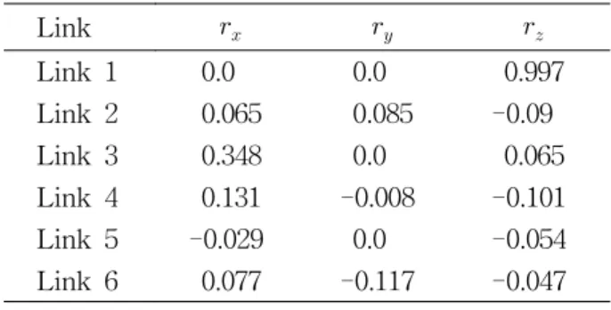
Table 2 Center of gravity (meters)
Table 3 Inertia tensor
Link centers of gravity values are given in Table 2. The term of , and refer to x, y and z coordinates of the center of gravity in the coordinates frame attached to the link. The moment of inertia about the center of gravity for each link is shown in Table 3. For each link, the coordinate frame of inertial terms is placed at the center of gravity, parallel to the attached frame used in Table 2.
4. Simulation results
Our proposed platforms is tested and evaluated on JS-10 robot, a industrial manipulator with 6R joint.
4.1 Motion control
The E-E of JS-10 firstly move to (0.4,0.3,0.4) in one second from home position. Then the E-E tracks a circle centered at (0.4,0.1,0.4) with a 0.2 m radius in the yx plane in two seconds. The trajectory is designed based on linear function with parabolic blends to assure smooth motion5).
Control law is given by
(18) with Kp=5.0e04, Kv=1.0e03. Table 4 shows the position errors when the model mismatch occurs.
Table 4 Robustness to parameter uncertainty Error of (%) Position error(m)
-10 3.2886e-004
-20 4.1567e-004
-30 5.9365e-004
4.2 Unified motion and force control
Task consist of motion control in straight line until the E-E of JS-10 impacts, impact force control, and contact force control below some limits(10N). JS-10 does not know the existence of a wall in advance. Robot can only detect the impact using a force sensor installed at the wrist.
Figure shows the process of the task and the
result of force control.
5. Conclusions
In this research, we have presented the platform
(a) Home Position (b) Motion Control
(c) Force Control (d) Force result Fig. 4 Process of unified motion and force control
task and the result of force control.
that provides a systematic framework for a new methods of modeling a robot manipulator on operational space. This platform is computationally efficient and allow us to develop calculation of jacobian and dynamic equations. We have shown that this method can provide a unifying framework for approaching manipulation tasks in industrial manipulator or in humanoid robots. The 3D CAD model of JS-10 robot manipulator was adopted as a case example and followed the procedure proposed in this paper, from 3D modeling to a unified motion and force control algorithm on the operational space.
The results of simulation confirm the efficiency of our proposed method. This method shows that it has considerable robustness about variation of the dynamic parameters and a great potential for dynamically consistent control, compliant control and other favorable properties with applications from E-E control of manipulators up to gait execution of humanoid robots.
The future work primarily focuses on
experimenting the real JS-10 manipulator to make a comparison between the real JS-10 manipulator and virtual 3D CAD model and verify the efficacy of our proposed platform.
Acknowledgement
This work was supported by the Pukyong National University Research Fund in 2008 (PK-2008-046).
Reference
1. M. Spong, 1996, "Motion control of robot manipulators”, In Handbook of Control. CRC Press, pp. 1339~1350.
2. T. Yoshikawa and O. Khatib, 2008, “Compliant motion control for humanoid robot in contact with the environment and humans”, IEEE Int.
Conf. on Intelligent Robots and Systems Acropolis Convention Center, pp. 211-218.
3. P. Neto, N. Mendes, J. N. Piers and A. P.
Moriera, 2010, "3D-Based robot programming:
the role of fuzzy-PI force control in unstructured environments", IEEE Int. Conf. on Automation Science and Engineering, pp.
362-367.
4. A. R. Chowdhury, B. Prasal, V. Kumar, R.
Kumar and S. K. Panda, 2011, "Design, modeling and open-loop control of a BCF mode bio-mimetic robotic fish", Int. Siberian Conf. on Control and Communications, pp. 87-92.
5. J. Craig, 2005, “Introduction to robotic:
Mechanics and control”, Prentice hall, pp. 69-75.
6. O. Khatib, 1987, “A unified approach for motion and force control of robot manipulators: The operational space formulation”, IEEE J. Robot.
Automat, vol. RA-3, no. 1, pp. 43-53.
7. T. M. Lim, 2005, "Unified force and motion control using an open system real-time architecture on a 7 DOF PA-10 robot", Int.
Conf. on Advanced Intelligent Mechatronics, pp.
1523-1528.
8. D. S. Ahn, and K. H. Park, 2011, "Unified
control for contact force and motion of industrial manipulator in operational space", Proc. of KSPSE 2011 Spring Conference, pp.
36-41.
9. Simlab co., LTD, www.simstudio.co.kr
10. B. Armstrong, O. Khatib and J. Burdick, 1986,
"The explicit dynamic model and inertial parameters of the PUMA 560 arm", IEEE Int.
Conf. on Robotics and Automation, pp. 510-518.