Micro/Millimeter-wave Photonic Pulse Train Generation by using Low-Speed Electronics and Optical Repetition
Rate Multiplication
J. M. Lee * and D. S. Seo *
Abstract
20 GHz and 40 GHz micro/millimeter-wave photonic pulse trains have been generated from a fiber ring laser with a semiconductor optical amplifier (SOA) by injecting 2 GHz gain-switched Fabry-Perot laser diode (GS-FPLD) output.
To achieve efficient cross-gain modulation in the SOA at 20 GHz and 40 GHz, individual lasing modes of the 2 GHz GS-FPLD output separated to 25 and 50 picoseconds respectively by passing dispersion compensating fibers.
Keywords : Optical pulse source, Mirco/millimeter-wave photonics, Repetition rate multiplication, Semiconductor fiber ring laser, optical communication network.
* Dept. of Electronics and MITERI, MyongJi University.
※ This work was supported in part by Inha University Engineering Research Center (OPERA) and the KRF (#D00694).
Manuscript received Aug. 23, 2007; accepted Sept. 20, 2007.
I. Introduction
High frequency optical pulses are very attractive for many applications, such as microwave/millimeter-wave photonics, high-speed optical time-division multiplexing optical communications, high-speed optical sampling, optical code division multiple access, etc. [1,2].
To generate such pulses, expensive high-speed electric sources and components to cover the pulse frequency are required. Therefore, the pulse speed is limited generally by the bandwidth of electronic components. Several techniques to overcome the electrical bottle neck have beuen suggested.
Among them, a repetition rate multiplication of a lower-speed but stable and easily manageable pulse source using relatively low speed electronics, is known to be a promising method due to its simplicity and low cost. Several multiplication methods based on dispersive fibers [3] or superstructured chirped fiber Bragg gratings (SSFBGs) [4]
have been implemented and showed promising results.
However, the former requires too long fibers approaching an order of 1 km, while the latter, even if it requires only a ~1 cm long fiber, shows a different spectrum from pulse to pulse. Integrated planar lightwave components (PLCs) have been used to get considerably high repetition rate multiplication factors for optical time division multiplexing [5]. The PLCs used for the multiplication function are based on a cascaded 2 x 2 power splitter/combiner geometry which gives inherent high insertion loss. Moreover, the multiplied outputs obtained by those methods failed to show wavelength tunable capability which is essential for some applications. Another promising method based on similar sequential time delay property of the waveguides in an arrayed waveguide grating (AWG) showed very high speed and repetition rate multiplication factors [6]. However, it required a special AWG with flat-top loss at the guides, resulting in a big AWG insertion loss. Those methods mentioned above generally utilized ultrashort pulse and large spectral width characteristics of a low-speed pulse source, requiring additional pulse compression [7].
Recently, repetition rate multiplication in a semiconductor fiber ring laser (SFRL) by a rational harmonic mode-locking [8] has been reported. To improve the modulation speed of a semiconductor optical amplifier (SOA) in the SFRL, instead of direct modulation of the SOA, a cross gain modulation (XGM) has been applied and achieved
method is that they use another mode-locked fiber source to inject light into the SOA for XGM. This results in complexity and high cost, even if it does not need a pulse compressor. More cost effective method in which the mode-locked fiber laser is replaced by a cheap gain-switched laser diode (GS-LD) has been reported [9].
They generated 40 GHz pulse bursts by applying an appropriate dispersion to a 10 GHz gain-switched Fabry-Perot laser diode (GS-FPLD) output and injected the burst into an SFRL for XGM in an SOA.
In this paper, we use a similar method with Ref. [9] but much lower speed GS-FPLD output at 2 GHz, leading much higher repetition rate multiplication factors up to 20. This indicates our method can be implemented by much cheaper and lower-speed electronic components.
Ⅱ. Experiment
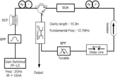
Our experimental set-up is shown in Fig. 1. A FPLD with ~1.2 nm mode spacing was gain switched by sinusoidal modulation at 2 GHz. After passing a band-pass filter (BPF) with a flat top pass-band of 6 nm to select an appropriate number of excited modes, the band-passed output applied to a dispersion compensating fiber (DCF) to form pulse bursts at 40 GHz or 20 GHz, respectively.
Fig. 1. Experimental Setup
The pulse burst injected into the SOA to modulate the SOA gain for mode-locking of the SFRL. Now we discuss the operation of each module in details.
Gain switching of a semiconductor laser diode is one of most simple methods to generate short optical pulses. The output pulse width depends strongly on the DC bias current and RF power which are applied to the laser. To find the optimum condition for shorter pulses, we examined the dependence of the pulse width on the DC bias and RF power, as shown in Fig. 2. The pulse width reduces as the RF power increases, whereas there is an optimum value of DC bias current.
Fig. 2. Pulse width of the GS-FPLD output as a function of the DC bias current and RF power.
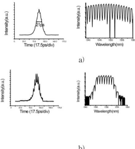
We fixed the bias current at 12.6 mA and the RF power at 31 dBm where the GS-FPLD output showed 21 ps pulse width at full width at half maximum (FWHM). To select several modes among excited multi-spectral modes we passed a band-pass filter (BPF) with a flat top pass-band of 6 nm. Fig. 3 shows the autocorrelation traces and optical spectra of the GS-FPLD output (a) and BPF output (b). The BPF passed ~6 modes as expected and its autocorrelation trace showed spikes due to more clear interference between modes. We found that better mode-locking in SFRL was achieved when we injected the BPF output than the direct output. This might be come from some possible errors in mode separation or delay, resulting in pulse broadening at overlapped region between neighborhood pulse bursts due to too many spectral modes. In addition to that relatively small number of modes make easy to synchronize the SOA gain modulation with the circulating pulses inside the fiber ring laser.
0 35.0 70.0 105.0 140.0 175.0
21ps
Intensity(a.u.)
Time (17.5ps/div)
1540 1545 1550 1555 1560
Intensity(a.u.)
Wavelength(nm)
0 35.0 70.0 105.0 140.0 175.0
Intensity(a.u.)
Time (17.5ps/div)
1540 1545 1550 1555 1560
Intensity(a.u.)
Wavelength(nm)
0 35.0 70.0 105.0 175.0
Intensity (a.u.)
Time (17.5ps / div)
a)
b)
Fig. 3. Autocorrelation trace (left) and optical spectrum (right) of GS-FPLD output; (a) before and (b) after passing the BPF.
2. Mode Separation by a DCF
To obtain 25 ps or 50 ps delay between neighborhood spectral modes, we determined the length of dispersive fiber simply by Eq. (1).
(1)Where, L is the fiber length, D the dispersion,
the delay time, and
the mode separation. Note that a GS-FPLD output shows a red chirp which can be compensated by passing a DCF with a negative dispersion.Therefore, we used a DCF to give an appropriate delay and pulse compression simultaneously to each mode. We prepared two kinds of available DCFs; a 400 m fiber with -55.2 ps/nm/km and a 600 m fiber with -38.2 ps/nm/km dispersion. We used the former for 25 ps delay and both fibers connected in serial for 50 ps delay.
Fig. 4. Autocorrelation traces of the 40 GHz (upper) and 20 GHz (lower) pulse bursts obtained by passing the band-passed GS-FPLD output through the DCFs.
Fig. 4 shows the autocorrelation traces of the output after passing the DCFs. We can clearly see the pulse delays of 25 ps and 50 ps between the neighborhood modes, proving the corresponding repetition rates of 20 GHz and 40 GHz respectively. Note also that each pulse in the burst, even if it is not optimized at the maximum compression condition, has been compressed to 10 ps. This pulse burst was amplified to 2 dBm by an EDFA, and injected into the SFRL through an optical circulator for XGM in SOA.
3.Mode-lockingofanSFRLbyExternalLightInjection
The length of the SFRL cavity was 15.3 m, which resulted in a fundamental cavity resonance frequency of 12.7 MHz. To get a stable harmonic mode-locking at 20 GHz or 40 GHz, the cavity length was controlled by an optical delay line. The SOA was biased at 150 mA and showed a signal gain of 20 dB. A fiber polarization controller (PC1) was used to assure maximum XGM of the SOA by the injected pulses.
An isolator and a polarization controller (PC2) ensured unidirectional operation of the SFRL and optical polarization matching in the SOA. A tunable BPF with a pass band of 1.2 nm inside the ring laser was used to select the wavelength of the output pulses. The 90 % of the ring laser output coupled to the ring laser cavity again by a 9:1 coupler. The choice of the output coupling ratio was a critical to the output performance since the output ratio must be high enough to ensure that the cavity round-trip signal should be strong enough to sustain mode-locking triggered by the injected pulse burst.
The mode-locked output was measured by a fast sampling scope coupled with a fast photo-detector.
0.0 100.0p 200.0p 300.0p 400.0p
In te n s it y (a .u .)
Time[100ps/div]
1562.5 1563.0 1563.5 1564.0 1564.5 1565.0
Intensity(a.u.)
Wavelength (nm)
0 35.0 70.0 105.0 175.0
Intensity (a.u.)
Time (17.5 ps/div)
50ps
III.ExperimentalResults
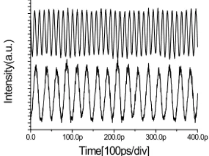
Fig. 5 shows the mode-locked output pulse trains measured by a 25 GHz sampling scope coupled with a 24 GHz photodetector. We can see clear pulse trains at 20 GHz and 40 GHz. In this way, we can generate high frequency microwave/millimeter-wave photonic waveforms based on low cost 2 GHz electronics and optical repetition rate multiplication. Fig. 6 shows the output pulse spectra for 20 GHz and 40 GHz trains. The measured spectral widths are 0.8 nm and 1.2 nm, respectively.
Fig. 5. Sampling scope traces of the SFRL outputs showing 40 GHz (upper) and 20 GHz (lower) pulse trains, respectively.
Larger spectral width at 40 GHz is understandable, since the pulse width of the mode-locked output is inversely proportional to the modulation frequency [10].
Fig. 6. S F R L
output spectra of the 40 GHz (upper) and 20 GHz (lower) trains.
Fig. 7 shows the measured autocorrelation trace of the 20 GHz pulses of which frequency is confirmed again by the 50 ps spacing between pulses. The measured pulse width was 5 ps, resulting in the time bandwidth product (TBP) of 0.48.
transform-limited.
Fig. 7. Autocorrelation trace of the 20 GHz mode-locked output showing 5 ps pulse width.
The wavelength tuning range would be determined by the gain bandwidth of the SOA, not by the input pulses.
However, the tuning range in our system was limited by the BPF inside the SFRL and the output was tunable from 1540 to 1570nm
IV.Conclusion
In this paper, we reported a noble method to generate wavelength tunable 20 GHz and 40 GHz pulse trains from a semiconductor fiber ring laser by an optical repetition rate multiplication of 2 GHz GS-FPLD output. The repetition rate multiplication achieved by injecting a pulse burst into the SFRL for SOA cross gain modulation. The pulse bursts at 20 GHz and 40 GHz were formed by delaying individual lasing modes of the 2 GHz GS-FPLD output to 25 and 50 picoseconds respectively by passing dispersion compensated fibers. By cross gain modulation of the SOA using the pulse burst, we could achieve a stable mode locking of the SFRL. The mode-locked output showed the 5 ps and 0.8 nm of time and spectral widths at 20 GHz, resulting in the TBP of 0.48. This means that we can generate microwave or millimeter wave waveforms by cost effective, low frequency electronics and optical repetition rate multiplication. In addition, we could achieve wavelength tuning over 20 nm by controlling the BPF inside the SFRL cavity.
References
[1] I. Shake, H. Takara, S. Kawanishi and M.
Saruwatari, "High-repetition-rate optical pulse generation by using chirped optical pulses," IEEE Electronics Lett., vol. 34, pp. 792-793, April 1998.
[2] Jian He and K.T. Chan, "All-optical actively modelocked fibre ring laser based on cross-gain modulation in SOA,"IEEE Electronics Lett., vol. 38, pp. 1504-1505, No*vember 2002.
[3] S. Arahira, S. Kutsuzawa, Y. Matsui, D.
Kunimatsu, and Y. Ogawa, "Repetition-frequency multiplication of mode-locked pulses using fiber dispersion,"J.Lightwave Technol., vol. 16, pp. 405-410, March 1998.
[4] J. Azana, P. Kockaert, R. Slavik, L.R. Chen, and S.
LaRochelle, "Generation of a 100-GHz optical pulse train by pulse repetition-rate multiplication using superimposed fiber Bragg gratings," IEEE Photon.
Technol. Lett., vol. 15, pp. 413-415, March 2003.
[5] T. Yamamoto, E. Yoshida, K.R. Tamura, K.
Yonenaga, and M. Nakazawa, "640-Gbit/s optical TDM transmission over 92 km through a dispersion-managed fiber consisting of single-mode fiber and "reverse dispersion fiber"," IEEE Photon, Technol. Lett., vol. 12, pp. 353-355, March 2000.
[6] D.S. Seo, D.E. Leaird, A.M. Weiner, S. Kamei, M. Ishii, A. Sugita, and K. Okamoto, “Continuous 500 GHz pulse train generation by repetition-rate multiplication using arrayed waveguide grating”Electron. Lett., vol.
39, no. 15, pp. 1138-1140, Jul. 2003.
[7] D.S. Seo, A.M. Weiner, "Ultrashort Optical Pulse Generation at 10 GHz by Pulse Compression of Actively Mode-Locked Fiber Laser Output", 한국전기 전자학회 논문지, 9권 2호, pp. 115-122, 2005. 12.
[8] Young Min Jhon, Kyoung Sun Choi, Young Tae Byun, Jae Hun Kim, Seok Lee and Dong Sun Seo,
"Pulsewidth-variable relaxation-free optical millimeter-wave generation from a semiconductor fiber ring laser,"IEEE Photonics. Tech. Lett., vol. 16, pp.1158-1160, April 2004.
[9] M.W.K. Mak, H.K. Tsang and H.F. Liu,
"Wavelength-tunable 40GHz pulse-train generation using 10GHz gain-switched Fabry-Perot laser and semiconductor optical amplifier," IEEE Electronics Lett., vol. 36, pp. 1580-1581, August 2000.
[10] Govind P. Agrawal,Nonlinear Fibre Optics. 2nd ed., New York: The Institute of Optics University of
*
Rochester, 1995.
Biography
Dong Sun Seo (Member)
D. S. Seo received the B.S. and M.S. degrees in electronics engineering from Yonsei University, in 1980 and 1985, respectively, and Ph.D. degree in electrical engineering (optoelectronics) from the University of New Mexico, USA, in 1989. In 1990, he joined the faculty of Myongji University, where he is a Professor with the Department of Electronics. From 1994 to 1995, he was a Visiting Research Fellow at the Photonics Research Laboratory, University of Melbourne, Australia. From 2002 to 2004, he was a Visiting Research Professor with the School of Electrical and Computer Engineering, Purdue University, USA. His current research interests are in the areas of ultra short pulse technology, optical CDMA, microwave photonics, optical communications. and optical measurements.
Jung Min Lee (Member)