• 검색 결과가 없습니다.

Ni Nanoparticles-hollow Carbon Spheres Hybrids for Their Enhanced Room Temperature Hydrogen Storage Performance

N/A
N/A
Protected

Academic year: 2021

Share "Ni Nanoparticles-hollow Carbon Spheres Hybrids for Their Enhanced Room Temperature Hydrogen Storage Performance"

Copied!
8
0
0

로드 중.... (전체 텍스트 보기)

전체 글

(1)

DOI: http://dx.doi.org/10.7316/KHNES.2013.24.6.550 eISSN 2288-7407

Ni Nanoparticles-hollow Carbon Spheres Hybrids for Their Enhanced Room Temperature Hydrogen Storage Performance

JIN-HO KIM, KYU-SUNG HAN

Icheon branch, Korea Institute of Ceramic Engineering and Technology Icheon-si, Gyeonggi-do, 467-843, Republic of Korea

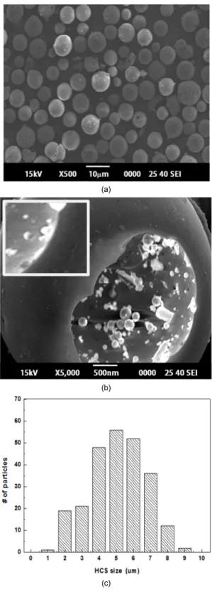
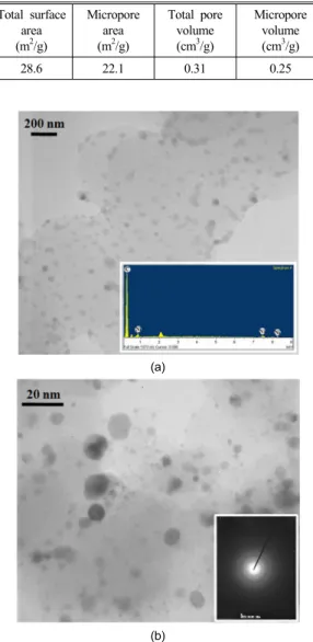
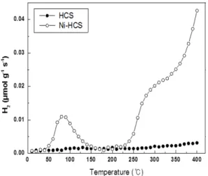
Abstract >> A glucose hydrothermal method is described for preparing hollow carbon spheres (HCS), which have a regular morphology and a high Brunauer-Emmett-Teller surface area of 28.6 m2/g. Scanning electron microscopy shows that they have thin shells and diameter between 2 and 8 μm. The HCSs were modified for the enhanced room temperature hydrogen storage by employing Ni nanoparticles on their surface. The Ni-decorated HCSs were characterized by X-ray diffraction, transmission electron microscopy coupled with an energy dispersive spectroscope, and an inductively coupled plasma spectrometer, indicating that fine and well-distributed Ni nanoparticles can be accomplished on the HCSs. The hydrogen uptake capacity in HCSs with and without Ni loading was evaluated using a high-pressure microbalance at room temperature under a hydrogen pressure upto 9 MPa. As much as 1.23wt.% of hydrogen can be stored when uniformly distributed Ni nanoparticles are formed on the HCSs, while the hydrogen uptake capacity of as-received HCSs was 0.41 wt.%. For Ni nanoparticle-loaded HCSs, hydrogen molecules could be easily dissociated into atomic hydrogen and then chemically adsorbed by the sorbents, leading to an enhanced capacity for storing hydrogen.

Key words : Hollow carbon spheres, Hydrogen storage, Glucose, Ni impregnation, Hydrothermal synthesis, Spillover effect

Corresponding author : [email protected]

[ 접수일 : 2013.11.24 수정일 : 2013.12.12 게재확정일 : 2013.12.31 ] Copyright ⓒ 2013 KHNES

1. Introduction

Environmental concerns regarding the use of fossil fuels and their predicted exhaustion have been impor- tant global issues. Hydrogen has been considered as an attractive alternative to fossil fuels, because its use can exclude the evolution of carbon dioxide. However, determining a practical means of safe and effective hydrogen storage is still a key issue for realizing the hydrogen-driven society. Carbon-based materials, such

as carbon nanotubes

1-3)

, carbon nanofibers

4,5)

, activated carbon

6,7)

, carbon aerogels

8,9)

, and recently graphene

10,11)

have been considered as one of the major candidates for effective hydrogen storage, due to their unique porous texture and large specific surface area.

Especially, the porous carbon structures have attracted a significant scientific interest and shown promising hydrogen storage capacities by tailoring their pore structure

12-14)

.

Among many carbon-based materials, hollow carbon

spheres (HCSs) should meet high standard of

hydrogen storage materials including low density due

to high surface area and large pore volume, chemical

(2)

stability, good thermal insulation. It has been tried to synthesize well-arranged HCSs with uniform size and porosity, using hydrothermal method

19,20)

, templated process

21,22)

, spray pyrolysis

23)

, reduction process

24)

and HCSs have potential applications such as catalyst supports

15-17)

, electrode materials for lithium rechargeable batteries

18)

, and hydrogen storage media

12)

.

Here, we adopted the hydrothermal reaction using glucose as the carbon source and sodium dodecyl sulfate (SDS) as an anionic surfactant to synthesize HCSs as an effective hydrogen storage adsorbent. This method is a scalable approach to obtain micron-sized HCSs ranging from 2 to 8 μm in diameter in large quantities and to easily control the morphology of HCSs and tune a reactive surface layer and void size in addition to its environmental friendliness. Moreover to further improve hydrogen uptake through the chemical adsorption of hydrogen atom, metal nanoparticle catalysts were dispersed on the surface of HCSs. The role of these metal nanoparticles is dissociation of hydrogen molecules to hydrogen atoms due to the spillover effect, resulting in an enhanced hydrogen uptake on the supporting carbon-based materials1

25-28)

.

2. Experimental

The HCSs were prepared by a hydrothermal method using glucose (C

6

H

12

O

6

,Sigma-Aldrich) as the carbon source and sodium dodecyl sulfate (SDS, CH

3

(CH

2

)

11

OSO

3

Na,Sigma-Aldrich) as an anionic surfactant.4.0 g of glucose and 0.1g of SDS were dissolved in de- ionized water and stirred with ultrasonication. This solution was moved into a 60ml stainless steel container.

Then temperature was elevated up to 180℃ and

maintained for 8h. The sample was naturally cooled down to room temperature. A dark precipitate was collected after several centrifugation processes with alcohol and de-ionized water and dried in a vacuum at 80℃ for 4h. Ni nanoparticles deposited on HCSs (denoted as Ni/HCS) were prepared by impregnating a constant amount of Ni precursor (Ni(NO

3

)

2

· 6H

2

O, Sigma-Aldrich) on the HCS support. For this reaction, sodium borohydride (NaBH

4

, Sigma-Aldrich) was used as a reducing agent. After the Ni impregnation process, the Ni/HCS were washed with de-ionized water and finally rinsed with ethanol for subsequent material characterization.

The amount of Ni nanoparticles deposited on HCSs was measured using an inductively coupled plasma spectrometer (ICP, Optima 5300 DV). The samples for ICP measurement were prepared by dissolving the Ni/HCS in 3 M HNO

3

solution for 2h. When Ni nanoparticles deposited on HCSs were completely dissolved in HNO

3

solution, the solution was then diluted with de-ionized water before ICP spectroscopy.

The surface morphologies of the HCSs were observed

by field emission scanning electron microscopy

(FESEM, JEOL JSM 6701F) operating at an acceleration

voltage of 10kV. Structural and morphological

characterizations were conducted by transmission

electron microscopy (TEM, Tecnai G2F30STwin)

operating at 300kV and an X-ray diffraction (XRD,

Rigaku D/Max 2500) with CuKα radiation in the

diffraction angle between 10

o

and 60

o

(2-theta),

respectively. N

2

adsorption is otherms were recorded

using a Quantachrome NOVA 1200 analyzer a t 77

K. The Brunauer-Emmett-Teller(BET) surface area

and the total pore volume were calculated using the

standard NOVA Win-P version 10.0 program. The

(3)

(a)

(b)

(c)

Fig. 1 FESEM analysis and particle size distribution of hollow carbon sphere synthesized by a glucose hydrothermal method: (a) x500 FESEM, (b) x5,000 FESEM, (c) histrogam

hydrogen adsorption was measured by gravimetric method using magnetic suspension balance (Rubotherm) in hydrogen pressure ranging from 0 t o 9 MPa at 293 K. For temperature programed desorption measure- ment, the evolved hydrogen was detected by a masss pectrometer (DS 6200) when the sample is heated upto 400℃ at rate of 10℃/min.

3. Results and Discussion

Fig. 1 shows the morphologies and size distribution of the HCSs synthesized by the glucose hydrothermal process. Most of HCSs have uniform spherical particles on microscale, and some of the ruptured particles definitely prove that the inside of these particles is hollow (Fig. 1(a)). The histogram in Fig. 1(c) displays the size distribution of HCSs indicating that their average particle size is 5.1μm and the size of HCSs ranges from 2 to 8μm from 256 particles. From the high magnitude FESEM image of a ruptured HCS’s surface (Fig. 1(b)), HCSs feature spherical shape with hollow core and thin shells, and their surface is very smooth and free of any cracks, arising from the presence of an inward force pressing the shell of the hollow particles by the evaporation of inner solvents.

From some fractured spheres, we could figure out that the shell of the HCSs has a thickness of approximately 50nm (inset of Fig. 1(b)). In addition, various forms of small particles could be occasionally found, possibly resulting from the incomplete decomposition of the glucose and SDS. In order to confirm the characteristic texture of the as-synthesized HCSs, N

2

adsorption isotherms at 77 K were measured, as shown in Table 1.

The isotherms exhibited a small hysteresis, suggesting

the diversity of pores and the presence of micropores

(4)

Table 1. BET analysis of hollow carbon by hydrothermal method

Total surface area (m

2

/g)

Micropore area (m

2

/g)

Total pore volume (cm

3

/g)

Micropore volume (cm

3

/g)

28.6 22.1 0.31 0.25

(a)

(b)

Fig. 2 TEM analysis of Ni-deposited HCSs synthesized by a glucose hydrothermal method (inset (a): EDS spectrum, inset (b): SAED pattern)

and mesopores in the product

22)

. According to the BET analysis, the total specific surface area and total micropore volume of the as-synthesized HCSs were 28.6m

2

/g and 0.31cm

3

/g, respectively.

With the capability of synthesizing uniform shaped and sized HCSs, we examined how metal nanoparti- cles affect hydrogen storage on HCSs. Metal nanoparti- cles can be used as a catalyst to decompose hydrogen molecules to atoms. We dispersed Ni nanoparticles on HCSs due to its catalytic performances and reasonable cost for enhanced hydrogen uptake capacity, which can be explained by a spillover reaction

1,27)

. The appearance of Ni nanoparticles distributed on HCSs was examined by TEM, as shown in Fig. 2. Fig. 2(a) and (b) show that Ni nanoparticles ranging from 5 to 20nm were well distributed on the surface of the HCS. The dark spots are Ni nanoparticles deposited on the HCS by the Ni-impregnation method. The Ni peaks appearing in the energy dispersive x-ray spectroscopy (EDS) result (inset of Fig. 2(a)) clearly confirm their presence on the HCSs. In order to check the loading quantity of Ni after its deposition, ICP spectroscopy was employed by dissolving the Ni-deposited HCSs in nitric acid, indicating that approximately 8wt.% of Ni is loaded on the HCSs.

The inset of Fig. 2(b) shows the selected area electron diffraction (SAED) pattern for the Ni-deposited HCS, and these patterns exhibit several well-defined rings.

The SAED pattern showing several rings indicate that the composites had a polycrystalline structure attributed to various diffraction planes of face-centered cubic (FCC) Ni deposited on the surface of HCSs.

The XRD patterns of HCSs with and without the impregnated Ni nanoparticles were shown in Fig. 3.

Fig. 3(a) proves that the as-synthesized HCSs by a

glucose hydrothermal method have only two broad

diffraction peaks at 26

o

and 43

o

, which could be

indexed as (002) and (101) planes of polyaromatic or

tubostratic carbon

19,24)

. Meanwhile, XRD pattern of

the Ni-deposited HCS (Fig. 3(b)) also includes a new

peak positioned at 44

o

in addition to the original

peaks attributed to carbon. As a result of indexing, it

(5)

Fig. 3 XRD patterns of hydrothermal HCSs decorated (a) without and (b) with Ni nanopoarticles (●: Graphite, ○: Ni)

Fig. 4 H

2

adsorption measurements of HCS without and with Ni deposition at room temperature

was disclosed that this peak is associated with (111) plane of face-centered cubic Ni. By applying the Scherrer equation

29)

to this peak, the average size of the impregnated Ni nanoparticles was estimated to be 8.5nm in accordance with the results observed from the TEM images in Fig. 2.

For the purpose of hydrogen storage, porous carbon- based materials with high specific surface area, large pore volumes, and uniform micropores are highly preferred. Fig. 4 compares the hydrogen adsorption capacity for as-prepared HCSs and Ni-impregnated HCSs, which were recorded in hydrogen pressure ranging from 0 to 9 MPa at 293 K. As shown in Fig.

4, the hydrogen uptake capacity for as-received HCSs and Ni-deposited HCSs tends to monotonically increase as the applied hydrogen pressure is elevated. The Ni-impregnated HCSs adsorb 1.23 wt.% of hydrogen at 293 K under 9 MPa, which is significantly larger than that of the as-prepared HCSs (0.41 wt.%). This remarkable increase in hydrogen uptake may be attributed to the dissociation-spillover effect of the impregnated Ni nanoparticles. Generally, hydrogen is

mainly stored by physical adsorption in the carbona- ceous materials, whereas metal catalyst including Ni can easily dissociate hydrogen molecule into hydrogen atom, which not only shows very fast migration on the support surface but also prefers the chemical adsorption with higher hydrogen uptake. In the past study of hydrogen storage in carbon nanotube (CNTs), Kim et al. reported that the CNTs decorated with Ni by an impregnation method have a higher hydrogen storage capacity than the pristine CNTs

2)

. Lin et al. found that as much as 1.27wt.% of hydrogen can be stored when Ni nanoparticles are uniformly distributed on the surface of CNTs, while the hydrogen uptake of the as-prepared CNTs was only 0.39wt.%

1)

. They reported that the enhanced hydrogen storage capacity of Ni/CNTs was attributed to the spillover reaction provided by Ni-decoration. In Fig. 5, the hydrogen programmed desorption profiles between 25℃

and 400℃ indicate that Ni-deposited HCS presents two different peaks, the first one at low temperature and the second on around 230℃ of onset temperature.

However, in the case of HCS without Ni-decoration,

(6)

Fig. 5 Temperature programmed hydrogen desorption profiles of HCS without and with Ni deposition

there is no desorption peaks over the whole region.

According to previous literatures, the first and second peaks correspond to hydrogen adsorbed on the metal on the support and the interaction between the metal and the support, indicating the presence of spill over effect, respectively

30)

. Therefore, it can be concluded that the higher hydrogen uptake for Ni-impregnated HCSs, as compared to the asprepared HCSs, results from not only physical adsorption facilitated by the high surface area and large volume of the micropores of HCSs but also the enhanced chemical adsorption due to a spill over effect induced by the impregnated Ni nanoparticles.

4. Conclusion

This work presents enhanced hydrogen storage performance of transition metal nanoparticles and carbonaceous hybrid material. Hydrothermal decom- position of glucose was an effective method for synthesizing hollow carbon spheres with high specific surface area and large pore volume. The combination

of SEM observation and N

2

adsorption isotherms at 77 K revealed the structure and morphology of well-defined hollow carbon spheres with a thin shell.

The particle size analysis for HCSs indicates that their average particle size is 5.1μm and the size distribution ranges from 2 to 8μm. After the successful synthesis of HCSs, Ni nanoparticles ranging from 5 to 20nm could be uniformly distributed on the HCSs via the impregnation process. ICP spectroscopy correlated to TEM analysis revealed that about 8 wt.% of Ni nanoparticles is impregnated and the crystallographic structure of nanoparticles corresponds to a polycrystalline FCC Ni. The hydrogen uptake of the Ni-impregnated HCSs was increased upto 1.23 wt.% due to the spill over effect provided by the Ni nanoparticles uniformly distributed on HCSs.

References

1. K.Y.Lin, W.T.Tsai, T.J.Yang, “Effect of Ni nanoparticle distribution on hydrogen uptake in carbon nanotubes”, J. Power Sources, Vol. 196, 2011, p. 3389.

2. H.S.Kim, H.Lee, K.S.Han, J.H.Kim, M.S.Song, M.S.Park, J.Y.Lee, J.K.Kang, “Hydrogen storage in Ni nanoparticle-dispersed multiwalled carbon nanotubes”, J. Phys. Chem. B, Vol. 109, p. 8983.

3. H.Lee, J.H.Kim, J.Y.Lee, “Hydrogen storage in Ni nanoparticles-dispersed multiwall carbon nanotubes”, Trans. of the Korea Hydrogen Energy Society, Vol. 13, No. 1, 2002, p. 74.

4. C.W.Huang, H.C.Wu, Y.Y.Li. “Hydrogen storage in platelet graphite nanofibers”, Sep.

Purif. Technol., Vol. 58, 2007, p. 219.

5. W.C.Xu, K.Takahasi, Y.Matsuo, Y.Hattori, M.Kumagai, S.Ishiyama, K.Kaneko, S.Iijima,

“Investigation of hydrogen storage capacity of

various carbon materials”, Int. J. Hydrogen

(7)

Energy, Vol. 32, 2007, p. 2504.

6. C.C.Huang, H.M.Chen, C.H.Chen, “Hydrogen adsorption on modified activated carbon”, Int.

J. Hydrogen Energy, Vol. 35, 2010, p. 2777.

7. W.Zhao, V.Fierro, C.Zlotea, E.Aylon, M.T.

Izquierdo, M.Latroche, A.Cezard, “Optimization of activated carbons for hydrogen storage”, Int.

J. Hydrogen Energy, Vol. 36, 2011, p. 11746.

8. H.Y.Tian, C.E.Buckley, S.B.Wang, M.F.Zhou,

“Enhanced hydrogen storage capacity in carbon aerogels treated with KOH”, Carbon, Vol. 47, 2009, p. 2128.

9. H.Y.Tian, C.E.Buckley, Paskevicius, D.A.

Sheppard, “Acetic acid catalysed carbon xerogels derived from resorcinol-furfural for hydrogen storage”, Int. J. Hydrogen Energy, Vol. 36, 2011, p. 671.

10. A.Ghosh, K.S.Subrahmanyam, K.S.Krishna, S.Datta, A.Govindaraj, S.K.Pati, “Uptake of H

2

and CO

2

by graphene”, J. Phys. Chem.C, Vol.

112, 2008, p. 15704.

11. L.P.Ma, Z.S.Wu, J.Li, E.D.Wu, W.C.Ren, H.M.

Cheng, “Hydrogen adsorption behavior of graphene above critical temperature”, Int. J.

Hydrogen Energy, Vol. 23, 2009, p. 2329.

12 . J.Jiang, Q.Gao, Z.Zheng, K.Xia, J.Hu, “Enhanced room temperature hydrogen storage capacity of hollow nitrogen-containing carbon spheres”, Int. J. Hydrogen Energy, Vol. 35, 2010, p.

210-216.

13 . H. Akasaka, T. Takahata, I. Toda, H. Ono, S.

Ohshio, S. Himeno, T. Kokubu, and H. Saitoh,

“Hydrogen storage ability of porous carbon material fabricated from coffee been wastes”, Int. J. Hydrogen Energy, Vol. 36, 2011, p.

580-585.

14 . Z. Yang, Y. Xia, and R. Mokaya, “Enhanced hydrogen storage capacity of high surface area zeolite-like carbon materials”, J. Am. Chem.

Soc., Vol. 129, 2007, p. 1673-1679.

15 . Z. Wen, Q. Wang, Q. Zhang, and J. Li, “Hollow carbon spheres with wide size distribution as anode catalyst support for direct methanol fuel cells”, Electrochem. Commun., Vol. 9, 2007, p.

1867-1872.

16 . J. Wu, F. Hu, X. Hu, Z. Wei, and P. K. Shen,

“Improved kinetics of methanol oxidation on Pt/hollow carbon sphere catalysts”, Electrochim.

Acta, Vol. 53, 2008, p. 8341-8345.

17 . A. A. Deshmukh, S. D. Mhlanga, and N. J.

Coville, “Carbon spheres”, Mater. Sci. Eng., R, Vol. 70, 2010, p. 1-28.

18 . F. Li, Q. Q. Zou, and Y. Y. Xia, “CoO-loaded graphitable carbon hollow spheres as anode materials for lithium ion battery”, J. Power Sources, Vol. 77, 2008, p. 546-552.

19 . B. Liu, D. Jia, Q. Meng, and J. Rao, “A novel method for preparation of hollow carbon spheres under a gas pressure atmosphere”, Carbon, Vol. 45, 2007, p. 668-689.

20 . X. Sun, and Y. Li, “Hollow carbonaceous capsules from glucose solution”, J. Colloid Interface Sci., Vol. 291, 2005, p. 7-12.

21 . Z. Yan, Z. Hu, C. Chen, H. Meng, P. K. Shen, H. Ji, and Y. Meng, “Hollow carbon hemis- pheres supported palladium electrocatalyst at improved performance for alcohol oxidation”, J. Power Sources, Vol. 195, 2010, p. 7146.

22 . F.L.Wang, L.L.Pang, Y.Y.Jiang, B.Chen, D.Lin, N.Lun, H.L.Zhu, R.Liu, X.L.Meng, Y.Wang, Y.J.Bai, L.W.Yin, “Simple synthesis of hollow carbon spheres from glucose”, Mater. Lett., Vol.

63, 2009, p. 2564.

23 . H.Hou, A.K.Schaper, F.Weller, A.Greiner,

“Carbon nanotubes and spheres produced by

modified ferrocene pyrolysis”, Chem. Mater.,

(8)

Vol. 14, 2002, p. 3990.

24 . L.Xu, W.Zhang, Q.Yang, Y.Ding, W.Yu, Y.Qian,

“A novel route to hollow and solid carbon spheres”, Carbon, Vol. 43, 2005, p. 1090.

25 . E.Yoo, T.Habe, J.Nakamura, “Possibilities of atomic hydrogen storage by carbon nanotubes or graphite materials”, Sci. Technol. Adv.

Mater., Vol. 6, 2005, p. 615.

26 . A.L.M.Reddy, Ramaprabhu, “Hydrogen storage properties of nanocrystalline Pt dispersed multi- walled carbon nanotubes”, Int. J. Hydrogen Energy, Vol. 32, 2007, p. 3998.

27 . M.Zielinski, R.Wojcieszak, S.Monteverdi, M.

Mercy, H.H.Bettahar, “Hydrogen storage in nickel

catalysts supported on activated carbon”, Int. J.

Hydrogen Energy, Vol. 32, 2007, p. 1024.

28 . J.Mao, Z.Guo, X.Yu, H.Liu, “Enhanced hydrogen sorption properties in the LiBH

4

-MgH

2

system catalysed by Ru nanoparticles supported on multi walled carbon nanotubes”, J. Alloys Compd., Vol. 509, 2011, p. 5012.

29 . A.Patterson, “The Scherrer Formula for X-ray particle size determination”, Phys. Rev., Vol.

56, 1939, p. 978.

30 . L.Zubizarreta, A.Arenillas, J.J.Pis, “Carbon

materials for H2 storage”, Int. J. Hydrogen

Energy, Vol. 34, 2009, p. 4575.

수치

Fig. 1 FESEM analysis and particle size distribution of  hollow carbon sphere synthesized by a glucose hydrothermal  method: (a) x500 FESEM, (b) x5,000 FESEM, (c) histrogam
Table 1. BET analysis of hollow carbon by hydrothermal  method Total surface  area (m 2 /g) Micropore area(m2/g) Total pore volume(cm3/g) Micropore volume(cm3/g) 28.6 22.1 0.31 0.25 (a) (b)
Fig. 4  H 2  adsorption measurements of HCS without and  with Ni deposition at room temperature
Fig. 5 Temperature programmed hydrogen desorption  profiles of HCS without and with Ni deposition

참조

관련 문서