• 검색 결과가 없습니다.

Evaluation of Particle Removal Efficiency during Jet Spray and Megasonic Cleaning for Aluminum Coated Wafers

N/A
N/A
Protected

Academic year: 2021

Share "Evaluation of Particle Removal Efficiency during Jet Spray and Megasonic Cleaning for Aluminum Coated Wafers"

Copied!
5
0
0

로드 중.... (전체 텍스트 보기)

전체 글

(1)

Evaluation of Particle Removal Efficiency during Jet Spray and Megasonic Cleaning for Aluminum Coated Wafers

Hoomi Choi*, Jaewon Min**, Atul Kulkarni***, Youngki Ahn*** and Taesung Kim*

,

***

*SKKU Advanced Institute of Nanotechnology, **Samsung Electronics

***School of Mechanical Engineering

ABSTRACT

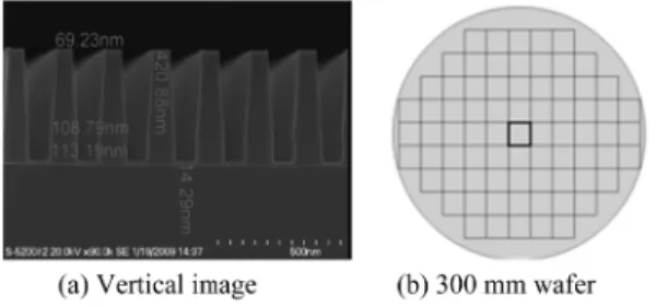
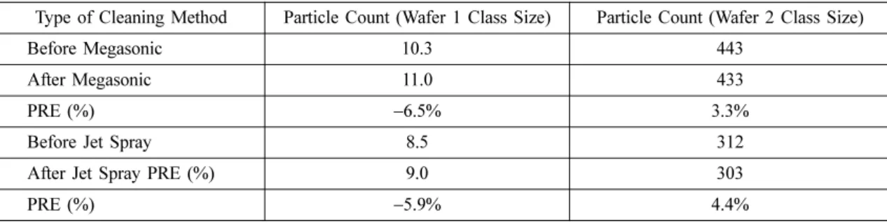
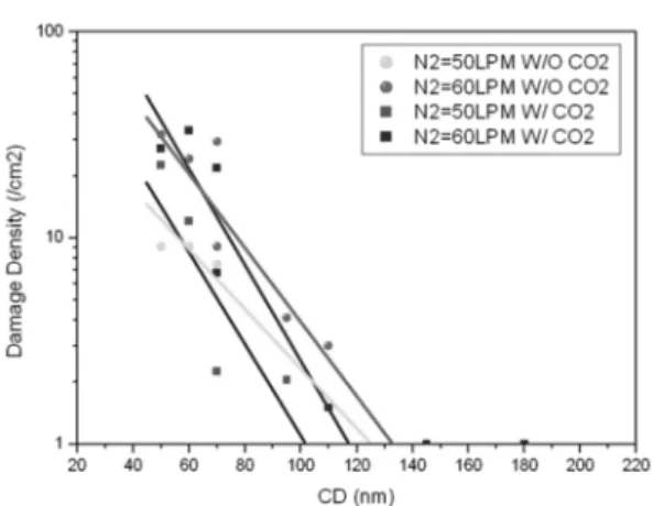
Among various wet cleaning methods, megasonic and jet spray gained their popularity in single wafer cleaning process for the efficient removal of particulate contaminants from the wafer surface. In the present study, we evaluated these two cleaning methods for particle removal efficiency (PRE) and pattern damage on the aluminum layered wafer surface. Also the effect of CO

2

dissolved water in jet spray cleaning is assessed by measuring PRE. It is observed that the jet spray cleaning process is more effective in terms of PRE and pattern damage compared to megasonic cleaning and the mixing of CO

2

in the water during jet sprays further increases the PRE. We believe that the outcome of the present study is useful for the semiconductor cleaning process engineers and researchers.

Key Words : Wet cleaning, Particle removal efficiency, Pattern damage, Functional water

1. Introduction

During semiconductor high speed device fabrication several metals were used as interconnects and contacts in the back end of line (BEOL) process. However, during the metal deposition process, there is a possibility of generation of unwanted particles which may get deposited on the wafer surface. This may lead to significant drop in the production yield during manufacturing of the devices. Hence, in the past, the importance to clean the substrate surfaces in the fabrication of semiconductor microelectronic devices has been recognized [1]. With the increase in the pattern densities for ULSI devices, need to remove numerous, small particles in order to obtain higher device yields to enhance the circuit reliability also increases. Many wafer cleaning techniques have been tested and several are being used as a backend cleaning such as megasonic and jet spray cleaning [2].

Megasonic cleaning is one of the well-established techniques used for particle removal in the semiconductor

industry [3,4]. Megasonic particle removal system was first described in 1979 [3], which is highly effective cleaning system due to its noncontact scrubbing action to the both sides of the wafer simultaneously. High intensity sound waves generate pressure fluctuations that result in cavitation bubbles which upon collapsing, release enough energy to dislodge and disperse particles but can also lead to pattern damage on the wafer [5]. High pressure fluid jet cleaning consists of a high velocity jet of liquid sweeping over the surface. Recently, two-fluid jet spray cleaning process has been applied. This method is cost-effective as compared to other methods because it utilizes only gas and operating liquid at room temperature [6-9]. Various types of liquids are available to use as an operating liquid such as, DI water and organic solvents. The shear forces effectively dislodge submicron particles and penetrate in to dense topography. However improperly adjusted pressures can make damage on a wafer surface or a pattern due to the operating pressure defines the spray velocity that is directly related to the momentum of generating droplet. Improper adjustment of the pressure may lead to the damage on the wafer surface

E-mail : [email protected]

(2)

or a pattern.

In the present study, we evaluated megasonic and jet spray cleaning methods for cleaning aluminum layered wafer surface for their particle removal efficiency (PRE) and pattern damage if any. Sonic waves with frequency of approximately 1 MHz are directed from transducer array panels to the wafer.

We also demonstrated the addition of CO

2

in DI water changes the pH of DI water and hence enhance the cleaning performance.

2. Experimental

2.1. Cleaning Methods

Dynamic random access memory (DRAM) alumi- num layer wafers (300 mm in diameter) were used to analyze and to compare the PRE during both megasonic (D-SONIC, SEMES) and jet spray (S- SPRAY, SEMES) cleaning methods. We used metal line formation process which is a part of commercial semiconductor manufacturing process to contaminate the wafers. Aluminum film of thickness of 600 nm can be formed using this process. However, during this process the wafer surfaces are contaminated by random generated dust particles from the chamber wall or suspended dust particles in transport system.

The reason we used this deposition process is to achieve actual contamination condition during manufacturing process instead of colloid doping on the bare wafer.

The schematic of both wet cleaning process is depicted on the Fig. 1. The operating frequency in megasonic is 1 MHz, and jet spray operates based on 50 and 60 lpm (liter per Minuit) of N

2

flow. These flow parameters are as per commercial semiconductor manufacturing process.

We evaluated the effect of CO

2

during jet spray cleaning process on a strip patterned wafer. The pattern for damage experiments was prepared by photo lithography and images are depicted in the Fig. 2.

These patterns were formed by lithography and etching process after poly-SiO

2

film deposition on the poly-Si coated bare wafer. One cell consists of the same shaped 12 patterns with 50 nm~180 nm of pitch sizes and exists in both vertically and horizontally. As 75 cells are formed on a single wafer, the total

numbers of patterns are 1800 EA (12×2×75). The depth of the pattern is 420 nm and pitch sizes are 50 nm~180 nm. Thus the aspect ratio of pattern ranges from 1:8 to 1:2. The current (I) flow through all (1800 EA) strip pattern, which is a measure of pattern damage, was recorded to estimate the number of pattern damaged patterns. It is known that the pH of DI water used in jet Spray can affect the particle removal process [10 ], hence we monitored the pH of DI water with and without CO

2

gas using pH meter (PH1500, EUTHEC) during jet spray cleaning process.

2.2. Analysis Methods

The number of particles on the wafer was measured before and after each cleaning process with defect analysis system (AIT, KLA-Tencor Co.).

Particle count measurements performed using an AIT provides the information of under layer particles, scratches and fallen (lose) particles. The particles morphology is classified using scanning electron microscope (SEM). The chemical com- positions of the particles were analyzed using energy dispersive X-ray microanalysis (EDX, RS- 4000 Hitachi).

Fig. 1. Schematic diagram of cleaning methods.

Fig. 2. SEM image of DRAM strip pattern used in jet

spray cleaning method.

(3)

3. Results and Discussion

Wafers were selected randomly after each deposition of aluminum layer for the evaluation of PRE using AIT before and after both types of cleaning. Contaminant particle shape and dimension are analyzed by scanning electron microscope (SEM, 5800 LV, JEOL Ltd.) and the compositions of particles are checked by energy dispersive X-ray microanalysis (EDX, RS-4000 Hitachi) as shown in Fig. 3. Particles contain several components such as Al, O, and Si with non-spherical shape. And to observe the morphology, initially we measured the overall distribution of contaminant particles by using AIT and then we checked each detected point by using SEM. Size of contaminant particles distributes 0.5~2 µm as shown in Fig. 3. A representative data of 6 wafers for the particle count is depicted in the Table 1.

As an inbuilt feature AIT classifies the total particle counts according to particle size range. It is observed that (from Table 1) the PRE measured by AIT is very low. AIT counts the number of contaminant particles including non-particles such as a scratch, contaminants

under deposited aluminum layer. Hence, to confirm these detected points are for real contaminant particles or not, we used SEM observations for PRE calculation. The analysis results of PRE are shown in Table 2, Fig. 4, and Fig. 5. The particle removal efficiency (PRE) is determined by averaging the values of each experimental case such as case 1 to 3.

Fig. 3. Morphology and composition of contaminating particles; (a) SEM images, (b) EDX spectrum.

Table 1. Particle Counts and PRE evaluated using AIT

Type of Cleaning Method Particle Count (Wafer 1 Class Size) Particle Count (Wafer 2 Class Size)

Before Megasonic 10.3 443

After Megasonic 11.0 433

PRE (%) −6.5% 3.3%

Before Jet Spray 8.5 312

After Jet Spray PRE (%) 9.0 303

PRE (%) −5.9% 4.4%

Table 2. Particle Counts and PRE were offered by SEM

Cleaning type Case 1 Case 2 Case

megasonic

1 2 average 1 2 average 1 2 average

4 18 22 1 7 8 76 65 141

3 4 7 0 3 3 29 10 39

25% 77.8% 68.2% 100.0% 57.1% 62.5% 61.8% 84.6% 72.3%

jet spray

3 14 17 1 8 9 70 63 133

0 2 2 0 2 2 4 5 9

100.0% 85.7% 88.2% 100.0% 75.0% 77.8% 94.3% 92.1% 93.2%

(4)

Each case represents the three different aluminum layers that formed by a metal line of DRAM. So the case 1 to 3 are the steps of manufacturing process and these wafers were tested under same experimental condition.

Jet spray method has 15%~20% higher cleaning performance than megasonic method as shown in Fig. 5 and table 2. Especially, removal result of case 3, which is contaminated by the highest particle concentration, shows the highest difference of PRE. It is seen that the PRE for jet spray cleaning is more effective than that of megasonic cleaning. In case of megasonic cleaning, sonic waves are directed from transducer array panels to the wafer. Cleaning is achieved through power density and frequency of the acoustic field, but the acoustic cavitation can be instrumental in dislodging particles from the wafer surface. On the other hand, in the jet spray cleaning micron sized water droplets were sprayed with high velocity which can remove the contaminant particles on the wafer surfaces. Operating liquid and gases are

supplied through separated external inlet and these are concurrently sprayed by a single nozzle exit [11].

It consists of a high velocity fluid jet that sweeps over a surface.

It is well understood that jet spray cleaning method is effective because it removes particles by physical force which is due to the impact of water droplet on the wafer surface. In the present study, carbon dioxide (CO

2

) gas dissolved DI water is used. The effect of CO

2

dissolved water on pattern damage is systematically evaluated with nitrogen (N

2

) gas flows which are used to create the jet. The pattern damage density (DD) is evaluated by measuring the current flowing through the pattern.

Experimental results to confirm the effect of CO

2

gas dissolved DI water are now depicted in Fig. 6.

This graph shows the damage density values and the critical dimensions by N

2

gas flow rate and dissolved CO

2

gas. Critical dimension (CD) means the width of the pattern pitch line. Lower damage density was achieved with CO

2

gas dissolved case at same CD value. This might be due to the reduction of adhesion force between the substrate and the particles. One of the strategies to increase the cleaning efficiency is to control the zeta potential of the surface and that of the particles. It is known that a zeta potential of the same sign to both the surface and the particles provides repulsive force between them. Repulsive force means weaker adhesion force and this will be stronger with higher absolute value [9]. In the present evaluation, Fig. 4. Particle maps and SEM images of PRE test; (a)

Particle map after megasonic cleaning (b) Particle map after jet spray cleaning.

Fig. 5. Particle removal efficiency of three cases on the aluminum surface.

Fig. 6. Damage Density (DD) and CD for various jet

spray conditions.

(5)

dissolved CO

2

gas changed the pH of DI water from 6.04 to 5.53. Due to this we observed the zeta potential changed from 43 mV to 50 mV. Which are similar to the values of the previous researched paper [12]. This change of operating liquid affects to both of the aluminum wafer surface and the aluminum particle. As we mentioned before, same sign with higher absolute value brings repulsive force. So pattern damage can be reduced at same condition with CO

2

gas.

4. Conclusions

In this study, we systemically evaluated megasonic and jet spray cleaning during semiconductor manufacturing process. We observed that jet spray cleaning is more effective than megasonic cleaning process for aluminum surface layer through PRE evaluation. Also we studied the effect of CO

2

gas dissolved in DI water, on particle removal, which reveals that this can further reduce the pattern damage.

Acknowledgments

This research was supported by Basic Science Research Program through the National Research Foundation of Korea (NRF) funded by the Ministry of Education, Science and Technology (2011- 0006268).

References

1. Ahn, Y., Ahn, D., Yang, J., Kulkarni, A., Choi, H., and Kim, T., “The effects of organic contamination and surface roughness on cylindrical capacitors of DRAM during wet cleaning process”, 반도체디스플 레이기술학회지, Vol. 10, pp. 1-4, 2011.

2. Tardif, F., Palleau, J., Lardin, T., Demolliens, O., Vin- cent, A., and Torres, J., “Wer cleanings adapted to backend processes”, Microelectronic Engineering,

Vol. 33, pp. 195-201, 1997.

3. Mayer, A. and Shwartzman, S., “Megasonic cleaning:

Anew cleaning and drying system for use in semi- conductor processing”, Journal of Electronic Materi- als, Vol. 8, pp. 855-864, 1979.

4. Kern, W., “Handbook of semiconductor wafer clean- ing technology”, Noyes publications, Park Ridge, NJ, 1993.

5. Burggraaf, P., “Wafer cleaning: Brush and high-pres- sure scrubbers”, Semiconductor International, Vol. 4, pp. 91-95, 1981.

6. Bardina, J., “Particles on surfaces 1: Detection, adhe- sion, and removal”, Plenum Press, NY, 1988.

7. Hattori, T., Hirano, H., Osaka, T., and Kuniyasu, H.,

“Environmentally benign single-wafer spin cleaning using ultra-diluted HF/nitrogen jet spray without causing structural damage and material loss”, IEEE Transactions on Semiconductor Manufacturing, Vol.

20, pp. 252-258, 2007.

8. Kanno, I., Yokoi, N., and Sato, K., “Water cleaning by water and gas mixture with high velocity”, in Cleaning Technology in Semiconductor Device Man- ufacturing V, The Electrochemical Society Proceed- ings Series, Pennington, NJ, PV 97-35, pp. 54-61, 1998.

9. Hirota, Y. Kanno, I., Fujiwara, K., Nagayasu, H., and Shimose, S., “Damage-free wafer cleaning by water and gas mixture jet”, Proceedings of International symposium on semiconductor manufacturing (ISSM), pp. 219-222, 2005.

10. Dugger, M., Jeon, J., Raghavan, S., Adkins, C., and Resnick, P., “Particle-surface interactions in chemical mechanical polishing”, Precision Engineering, Vol.

36, pp. 149-150, 1997.

11. Kim, Y., Cho, H., and Kim, J., “Megasonic free single wafer cleaning using ozone jet without pattern dam- age and with minimum substrate etching”, IEEE Transactions on semiconductor manufacturing, Vol.

17, pp. 261-266, 2004.

12. Reinhardt, K. and Kern, W., “Handbook of silicon wafer cleaning technology, 2nd edition”, Norwich, NY, 2007.

접수일: 2012년 7월 19일, 심사일: 2012년 8월 16일,

2 차심사일: 2012년 9월 3일, 게재확정일: 2012년 9월 17일

수치

Fig. 2. SEM image of DRAM strip pattern used in jet spray cleaning method.
Table 1. Particle Counts and PRE evaluated using AIT
Fig. 5. Particle removal efficiency of three cases on the aluminum surface.

참조

관련 문서