Manuscript received February 12, 2016, revised March 11, 2016, accepted March 15, 2016 ISSN 2465-8111(Print), 2466-0124(Online) DOI http://dx.doi.org/10.18770/KEPCO.2016.02.02.273
Evaluation of Degradation Characteristics of Thermal Barrier Coating on Gas Turbine Blades
Yongchan Jung
*†, Mintae Kim
*, Juhyeung Lee
*, Jamin Ahn
**, Kihong Kim
***
Creative Future Technology Lab., KEPCO Research Institute, Korea Electric Power Corporation, Daejeon 34056, Korea
**
Materials Engineering, Korea University of Technology and Education, Cheonan 330-708, Korea
† [email protected]
Abstract
In order to evaluate the lifespan of high-temperature parts with thermal barrier coating in gas turbines used for power generation, this study was performed on an 80 MW-class gas turbine exceeding 24 k equivalent operating hours. Degradation characteristics were evaluated by analyzing the YSZ (Yttria Stabilized Zirconia) top coat, which serves as the thermal barrier coating layer, the NiCrAlY bond coat, and interface layers. Microstructural analysis of the top, middle, and bottom sections showed that Thermal Growth Oxide (TGO) growth, Cr precipitate growth within the bond coat layer, and formation of diffusion layer occur actively in high-temperature sections. These microstructural changes were consistent with damaged areas of the thermal barrier coating layer observed at the surface of the used blade. The distribution of Cr precipitates within the bond coat layer, in addition to the thickness of TGO, is regarded as a key indicator in the evaluation of degradation characteristics.
Keywords : Gas turbine blade, thermal barrier coating, precipitates, metallurgical analysis
I. INTRODUCTION
While power stations are thoroughly maintained and inspected on a regular basis to ensure stable operations, there has been frequent cases of facilities suffering damage before reaching their design life. Such cases have occurred when there is inadequate response to the operating environment of facilities, corrosion sensitivity of materials, and structure-induced stress.
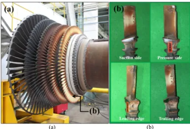
The most frequently occurring types of damage include corrosion, oxidation, fatigue, delamination and cracking [1]-[4]. This study seeks to evaluate degradation characteristics, such as high- temperature corrosion and oxidation, of gas turbines operating under high-temperature combustion conditions. The silo-type 80 MW gas turbine combustor used in this study consists of 15-stage compressors and 5-stage turbines. During normal operation, the upper combustor produces high-temperature flames with a turbine inlet temperature (TIT) of 1,100 °C, a flow of Mach 0.1- 1.0, and an internal pressure of 12.8 atm. Since the first stage blade is directly affected by the accelerated flames as shown in Fig. 1(b), it rapidly undergoes high-temperature corrosion and oxidation. In addition, the first stage blade is more susceptible to damage because of thermal fatigue caused by repeated stop/starts with electric power load management, and mechanical fatigue from a centrifugal force of about 100 MPa due to high-speed revolutions at 3,600 rpm.
Using nickel superalloy as the basic material, designing internal cooling holes, and applying thermal barrier coating on the surface are some attempts that have been made to enhance blade life. However, the current design life of the #1 blade stands at 24 k EOH (equivalent operating hour).
Against this backdrop, this study explains the degradation process of thermal barrier coating layers on used blades based on a comprehensive analysis of MCrAlY (M: Metal) bond coat,
YSZ top coat, and the interface of coating layers from a micro- structural perspective.
II. EXPERIMENT
The fully used blade, with a proposed life of 24 k EOH, of the 80 MW-class gas turbine is shown in Fig. 1. Delamination of the top coat, including damage to the basic material, can be observed on the leading edge, and partial delamination of the top coat is also seen on the trailing edge. These types of blade damage are similar to those previously reported [6][7]. However, to account for differences in the substrate material used in the blade, chemical composition of the bond coat and top coat,
(a) (b)
Fig. 1. 80 MW class land-based gas turbine. (a) the schematic of a gas turbine, (b) fully used #1 blade.
crystallinity and manufacturing process, this study performs a comprehensive analysis of the blade’s microstructure to evaluate the lifespan of thermal barrier coating from a microstructural perspective.
For this purpose, the blade was cut perpendicularly, and microstructural analysis was performed for the top (b), middle (c), and bottom (d) sections. The symbols E, T, M, B, P, and S stand for edge, top, middle, bottom, pressure side, and suction side. The pressure and suction sides are divided into three sections, from the leading edge to the trailing edge. Each section was analyzed for microstructure, chemical composition and hardness.
The equipment used in microstructural analysis and hardness measurement are as follows.
· Microstructure: LEICA DMI-5000M, SEM JEOL JSM-7001F
· Chemical composition: OXFORD INCA X-stream 2 energy
dispersive x-ray spectroscopy
· Hardness: MATSUZAWA ATM-7FS
Chemical composition analysis (see Table 1) revealed IN738LC as the substrate material and NiCrAlY as the bond coat.
III. RESULTS AND DISCUSSION
The thermal barrier coating on the first stage blade consists of 500 m top coat and 400 m NiCrAlY bond coat. Fig. 3 shows the microstructure of the middle edge (see ME in Fig. 2) of the blade, including the thermal barrier coating. The blade edge is the area first reached by high-temperature flames of 1,100 °C, and thus most susceptible to damage caused by high-temperature corrosion and oxidation. Observations of the leading edge found delamination on the top coat (see left area in Fig. 3), which also featured many fine cracks leading to the insides of the bond coat.
For a TIT of 1100 °C, when the top coat serving as a 150 °C thermal barrier is delaminated, high-temperature corrosion and oxidation are accelerated as the substrate material is directly exposed to high-temperature flames. Blade life is further reduced when cracks form at the interface of the top coat and bond coat.
Many cracks were found at the interface of the top coat and bond coat in high-temperature parts, with some cracks growing through the bond coat and into the substrate material (Fig. 4).
Most cracks entered the bond coat after growing in a single direction, while others were briefly restrained at the interface of the substrate material and bond coat followed by regrowth into the substrate material.
To provide an accurate understanding of the degradation process for thermal barrier coating on used blades, the following sections shall provide further explanation on microstructural
Fig. 2. Blade cutting for failure analysis. (a) The first stage blade, (b) tip, (c) middle, (d) bottom; red circle locations are analyzed.
Fig. 3. Microstructure in leading edge of the fully used blade (ME in Fig. 2).
Fig. 4. Cracking in pressure side (MP1 in Fig. 2). (a), (b), (c) low magnification, (d) high magnification of crack tip in (a).
analysis, chemical composition and crystal structure.
A. Microstructure
Plasma spraying is commonly used to protect gas turbine blades with thermal barrier coating. This method, which uses a plasma heat source to apply coating powder in consecutive order, gives coating layers of a lamellar structure as the final product.
While blades coated by plasma spraying have very low thermal conductivity due to numerous pores existing between accumulated powders, their low resistance to thermal fatigue has allowed widespread use in power stations, which have a lower operating
temperature and less repeated thermal cycle sets compared to aircraft gas turbines.
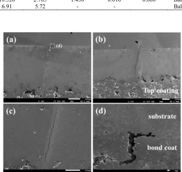
Fig. 5 presents the microstructure of the thermal barrier coating, which includes the substrate material of the used blade.
As can be seen in Fig. 5(a), the thermal barrier coating consists of the top coat and bond coat, and serves to protect the basic material from high-temperature flames. Fig. 5(b) is a magnification of the interface of the top coat and bond coat. The top coat was found to be of a layered structure and had many pores. The boundary between the bond coat and top coat featured Thermal Growth Oxide (TGO) of 7-36 m, while the boundary in contact with the bond coat had a 55 m Chromium Diffusion Layer (CDL). The microstructure of the bond coat, shown in Fig. 5(c), is comprised of matrix phases ϒ: Ni and ϒ’: Ni
3(Cr,Al), and chromium precipitates. In general, the bond coat enhances strength by increasing aluminum content to precipitate ϒ’: Ni
3Al or aluminum-rich β: NiAl on the ϒ: Ni matrix, but both ϒ’:
Ni
3(Cr,Al) and Cr precipitates are distributed in the ϒ: Ni matrix of the bond coat on the target blade of this study. More details on the generation and growth of precipitates are provided in 3.3 Bond coat and CDL.
The microstructure of the basic material IN738LC is shown in Fig. 5(d), which confirms the dense presence of rectangular- shaped ϒ’: Ni
3Al within the ϒ: Ni phase. Since spherification and coarsening of the ϒ’: Ni
3Al phase has a direct influence over mechanical properties of the substrate, it serves as an important
Fig. 5. Microstructure of TBC coating. (a) blade surface, (b) interface between top coat and bond coat, (c) phases in bond coat, (d) phases in substrate.
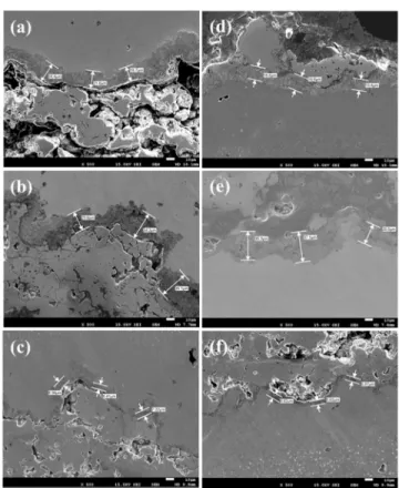
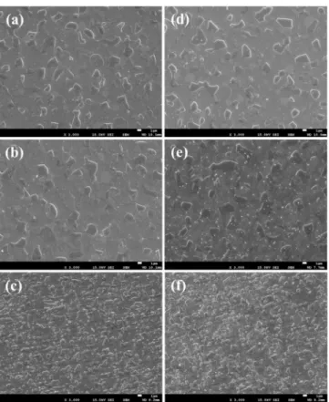
Fig. 6. TGO growth
- Pressure side(P1): (a) top, (b) middle, (c) bottom - Suction side(S1): (d) top, (e) middle, (f) bottom
Fig. 7. TGO thickness relationship between pressure side and suction side.
Fig. 8. TGO average thickness and standard deviation from top to bottom.
and increases residual stress in the surroundings [9]. Crack formation is initiated when TGO, with a width exceeding the effective thickness, is subject to thermal fatigue and repeated mechanical load. According to existing studies, the effective thickness of TGO is 10 m for aircraft gas turbines operating at 1,000 °C [7]-[9]. However, the used blade was observed to have several TGOs exceeding the effective thickness. The coarsened TGO, due to the increase in thermal stress and growth stress occurring during growth, can be seen as having provided the environment for multiple cracks to form as shown in Fig. 4, To assess the degradation of thermal barrier coating on the used blade, TGO thickness was measured for different sections, and the results are presented in Fig. 6 to Fig. 9. Fig. 6 shows the pressure side (P1) and suction side (S1) of the blade divided into top, middle, and bottom sections. The thickness of TGO increased in direct proportion to blade temperature. Similar to the pressure side, the suction side of the blade was divided into top, middle, and bottom. Measurements were taken for three sections of the pressure side as shown in Fig. 6(a) to 6(c), and for the three sections of the suction side in Fig. 6(d) to Fig. 6(f).
TGO growth was found to occur in various forms due to differences in surface temperature at each section of the pressure and suction sides. First, for a qualitative comparison of deviation in TGO thickness at the pressure and suction sides, the TGO thickness relationship between the two sides was plotted as shown in Fig. 7. The thickness of TGO fell in the range of 5 to 20 m for the bottom sections of the blade (black circles), with some growing to 30 m. Most measurements are distributed over the lower part of the graph, indicating that the pressure side had a higher operating temperature than the suction side. The thickness of TGO for the middle sections (red diamonds) ranged from 5 to 40 m, and the measurements were widely scattered.
TGO coarsened to 49 m or higher were observed in the pressure side. Similar to the bottom sections, TGO thickness for the bottom sections was more active in the pressure side. The thickness of TGO for the top sections (blue squares) fell under 10 to 37 m, with most growing to 20 m. The top sections had faster TGO growth in the pressure side than the suction side. The average thickness and standard deviation of TGO for the top to bottom sections are given in Fig. 8. The average thickness and standard deviation were 15.58 m and 5.35 m for the top section, 16.23 m and 11.95 m for the middle section, and 7.70
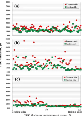
m and 4.40 m for the bottom section. TGO thickness was in the order of middle > top >> bottom, and thus consistent with blade damage areas shown in Fig. 2. Looking at TGO thickness values from the leading edge to the trailing edge (Fig. 9), we can see that TGO varies greatly in the pressure side of the top section, but tends to grow coarser at both ends of the leading edge and
trailing edge. The deviation of TGO thickness in the middle section is two times greater than that of the top section. In particular, TGO growth is fastest in the leading edge, where coarse-grained TGO close to 80 m were observed. Meanwhile, TGO thickness in the bottom section was mostly within 10 m, and TGO growth occurred at a faster rate in areas nearer to the leading edge.
Based on the above analysis, we can presume that the used
Fig. 9. TGO thickness values from leading edge to trailing edge. (a) top, (b) middle, (c) bottom.
Fig. 10. Chemical analysis of major phases in bond coat. (a) bond coat morphology, (b) Cr precipitate, (c) ϒ’, (d) ϒ.
blade becomes more overheated in the pressure side than the suction side, and in areas closer to the two ends of the leading and trailing edge. While the average TGO thickness in the bottom section was fairly acceptable at less than 10 m, the top and middle sections surpassed 15 m (maximum of 78 m). This indicates that thermal barrier coating layers of the top and middle sections have been used beyond their recommended life.
C. Bond coat and CDL
The bond coat enhances the adhesive power of the top coat, alleviates thermal stress caused by differences in thermal expansion coefficients between the substrate and ceramic top coat material, and also plays the role of improving resistance to oxidation and corrosion at high temperatures [10]. Various MCrAlY (M: Co, Ni, Co+Ni etc.) materials can be used to prevent oxidation and corrosion of blades. The cobalt-rich CoNiCrAlY is commonly used to improve corrosion-resistance at high temperatures (800-950 °C), but the bond coat of the used blade was the cobalt-free NiCrAlY, as presented in the chemical composition analysis in Table 1.
If aluminum content is sufficiently increased (≥ 5 wt%) in NiCrAlY, particles of the ϒ’: Ni
3Al phase become precipitated in traces in the ϒ: Ni phase. Since this achieves a hardening effect, NiCrAlY is a common bond coat in power generation gas turbines [11][12]. As shown in Fig. 5(c), the ϒ phase and ϒ’
phase can be observed in the NiCrAlY bond coat, along with Cr- rich precipitates. The ϒ: Ni phase is the matrix phase of the FCC structure. ϒ’: Ni(Cr,Al), is a phase that can be precipitated during manufacturing of the bond coat. It can be precipitated at the interface of the ϒ phase and within grains while cooling to room
temperature. During normal operation of gas turbines, the temperature of the bond coat is 800-900 °C, and continuous growth of the ϒ’ phase is possible due to the ageing effect. The used blade was depreciated to more than 24 k EOH, and the growth of ϒ / ϒ’ due to overaging can thus be determined. Cr precipitates within the bond coat are presumed to be of the secondary phase, which is expected to serve as an important indicator in evaluating the lifespan of the bond coat because its growth was in direct proportion to the operating time of the gas turbine. Microscopic analysis and chemical composition analysis on the ϒ and ϒ’ phases (Fig. 10), including Cr precipitates, showed that Cr precipitates generated multiple nuclei at the interface of the ϒ /ϒ’ phase and grew while encroaching on the ϒ’ phase. Fig. 11 presents Cr precipitates by section after excluding etching and performing micro-grinding. Similar to TGO growth, these Cr precipitates underwent coarsening in direct proportion to temperature. Looking at the pressure side (Fig. 11(a)-(c)) and the suction side (Fig. 11(d)-(f)), the Cr phase was found to have grown coarser in high-temperature areas, corresponding to the top and middle sections. The bottom section was able to maintain relatively lower temperatures because it was kept out of direct contact with the flames, and had a wide distribution of fine-grained Cr precipitates. Because of Cr growth and coarsening, the total number of Cr precipitates was smaller for the top and middle sections, but five times larger in size compared to the bottom. In order to establish a qualitative relationship between Cr precipitates and degradation of the used blade, the number of Cr precipitates per unit area was measured using a high magnification of X3,000. Fig. 12 shows the results of statistical analysis by section. The number of Cr precipitates per unit area was 82-108 for the top and middle sections, and 359-389 for the bottom section. While the total figure was a 1/3 reduction, the grains were at least five times coarser.
The above analysis shows that, similar to TGO growth, blade surface temperature becomes overheated in the top and middle sections. In addition, mechanical properties of the bond coat deteriorated due to coarsening of Cr precipitates in the top and middle sections. The average hardness (HV) in the top and middle sections fell by approximately 15%. This implies that the lifespan of thermal barrier coating layers has shortened due to the deterioration of mechanical properties of the bond coat.
Since Cr precipitates within the bond coat are rich in chromium, they face constraints in growth if a sufficient amount of chromium is not supplied. Fig. 9 presents the analysis results
Fig. 11. Chromium precipitates growth in bond coat.
- Pressure side(P1): (a) top, (b) middle (c) bottom - Suction side(S1): (d) top, (e) middle, (f) bottom
Fig. 12. Cr precipitates number and dispersion per unit area (317.55 m2).
for the Cr Diffusion Layer (CDL) formed at the boundary in contact with the top coat. Oxygen freely enters the top coat, which consists of a porous lamellar structure as shown in Fig.
5(b). Chromium existing in the bond coat turns into Cr
2O
3(4Cr+3O
2→2Cr
2O
3) before turning into Cr precipitates because of their high oxidizing power. As shown in Fig. 9(b), Cr is oxidized first if it is nearer the top coat, which has a higher concentration of oxygen. This tends to limit the nucleation and growth of Cr precipitates. The average thickness of CDL within the bond coat of the used blade was found to be 50 m.
IV. CONCLUSION
To evaluate the degradation characteristics of thermal barrier coating on high-temperature parts in 80 MW class gas turbines, this study conducted a microstructural analysis on the top coat, bond coat, and coating interfaces of a used blade after 24 k EOH.
This study derived key indicators for the evaluation of degradation characteristics of thermal barrier coating. In addition to TGO growth at the interface of the top coat and bond coat, coarsening of secondary Cr precipitates within the bond coat and formation of CDL are expected to serve as important indicators in evaluating the lifespan of thermal barrier coating.
This study determined the relationship between blade surface temperature and key indicators. TGO thickness at the middle and top sections, which have relatively higher surface temperatures, had three times the growth of the bottom section.
Cr precipitates within the bond coat grew five times coarser for the middle and top sections than the bottom section. The areas in which Cr precipitates experienced active coarsening showed a 15 % reduction in mechanical properties of the bond coat, along with delamination of the top coat and formation of multiple cracks. As such, thermal barrier coating layers of the top and middle sections appear to have been used beyond their recommended life.
This study proposed a mechanism for the nucleation and
growth of Cr precipitates within the bond coat. After being supplied with Cr from the ϒ phase, Cr precipitates grow while encroaching on Ni
3(Cr,Al), and this growth occurs more rapidly at high temperatures. However, further research is required on growth rate and point of nucleation.
The nucleation and growth of Cr precipitates is limited in CDL of the bond coat. At the interface of the top coat and bond coat, chromium oxides are formed when oxygen infiltrated through the top coat interacts with Cr diffused from the bond coat.
Since this reactions leads to continuous consumption of Cr existing in areas within the bond coat that are close to the interface, the lack of Cr prevents the nucleation and growth of Cr precipitates.
REFERENCES
[1] Yong Chan Jung, Tae Hee Lee and Ki Tae Kim, Eng. Fail. Anal.
32, 98~105 (2013).
[2] Min Tae Kim and Yong Chan Jung, Surf. Coat. Technol., 210, 166~175 (2012).
[3] Yong Chan Jung and Ki Tae Kim, Met. Mater. Int., 17, 279~282 (2011).
[4] Yong Chan Jung and Han Sub Chung, Met. Mater. Int., 16, 267~271 (2010).
[5] Aymeric Raffaitin, Fabrice Crabos, Eric Andrieu, Daniel Monceau,
Surf. Coat. Technol., 201, 3829~3835 (2006).[6] W.R. Chen, X. Wu, D. Dudzinski, P.C. Patnaik, Surf. Coat.
Technol., 200, 5863~5868 (2006).
[7] B.G. Mendis, B. Tryon, T. M. Pollock, K. J. Hemker, Surf. Coat.
Technol., 201, 3918~3925 (2006).