This is an Open-Access article distributed under the terms of the Creative Commons Attribution Non-Commercial License(http://creativecommons.org/licenses/by-nc/3.0) which permits unrestricted non-commercial use, distribution, and reproduction in any medium, provided the original work is properly cited.
Numerical analysis on the welding residual stress and fracture toughness of the heavy thick steel welded joints by welding processes
HanSur Bang* and HeeSeon Bang* , †
*Department of Welding and Joining Science Engineering, Chosun University, Gwangju 501-759, Korea
†Corresponding author : [email protected]
(Received October 7, 2014 ; Accepted April 13, 2015)
Abstract
This study examined the welding residual stress and fracture toughness of 78mm thick steel electro gas welding (EGW) and flux cored arc welding (FCAW) welded joints by numerical analyses of the thermal elasto-plastic behavior and fracture toughness(KIC). The residual stress, fracture toughness characteristics and production mechanism on the welded joints were clarified. Moreover, the effects of the welding process (EGW and FCAW) on the welding residual stresses and fracture toughness of welded joints were evaluated. The results showed that the new welding process (EGW) appears to be an effective substitute for the existing welding process (FCAW) in a thick steel plate with high strength.
Key Words : Heavy thick steel; Electro gas welding (EGW); Flux cored arc welding (FCAW); Welding residual stress; Fracture toughness
ISSN 1225-6153 Online ISSN 2287-8955
1. Introduction
To improve the economical benefit in the initial invest- ment and working operation, ships have become larger than conventional types, particularly in container ships
1-3)
. Along with this trend, such as container ships above 8000TEU, the use of high strength (>355N/mm
2) and thick steel plates EH36/EH40 (>70mm) in the con- struction of large sized ships has increased rapidly to satisfy the reduction of weight and increase the longi- tudinal strength of ships
4-7). The application of these ul- tra thick steel plates, however, place high demand on the workload for welding. Therefore, the necessities of a high efficient manufacturing processes in welding, such as one pole EGW(Electro Gas Welding) for 55mm below in thickness, and two pole EGW or one pole &
FCAW(Flux Cored Arc Welding) for 55mm above in thickness, were increased to overcome the difficulties with the conventional multi-layer welding process, such as semi-automatic arc welding, FCAW
8-13). As EGW, which is an automatic welding for time saving, is a welding process with large heat input, the mechanical properties of welding consumable and base metal can
be affected by potential brittle fracture. Furthermore, the crack susceptibility might be increased compared to the ordinary multi-layer welding process. Therefore, these thick steel plates, which are welded by large heat input, need to be treated by a post heat treatment at a controlled heat input to prevent further brittle fracture at the service stage
8-13). Acknowledging these deteriorations in fracture toughness and fatigue life on high strength ultra thick steel plates, which have been used in large- sized welding constructions, some classification soci- eties are considering the relevant requirements to esti- mate and reinforce the fracture toughness of a construction.
Owing to the intense concentration of heat during welding, the weld line and its vicinity undergo severe thermal cycles, which cause non-uniform heating and cooling of the material, thereby generating inhomoge- neous plastic deformation and residual stress in the joint. The presence of welding residual stress can be detrimental to the performance of the welded product.
For example, the tensile residual stress in the weld zone has been identified as a significant factor for reducing the resistance of the welded structure that contributes to the promotion of crack propagation and degradation of fatigue strength. Therefore, it is extremely important to
Research Paper
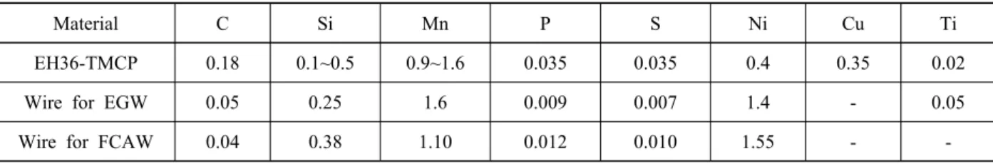
Material C Si Mn P S Ni Cu Ti
EH36-TMCP 0.18 0.1~0.5 0.9~1.6 0.035 0.035 0.4 0.35 0.02
Wire for EGW 0.05 0.25 1.6 0.009 0.007 1.4 - 0.05
Wire for FCAW 0.04 0.38 1.10 0.012 0.010 1.55 - -
Table 2 Mechanical properties of EH36-TMCP and wire (Wt%)
Material Y.S(N/mm
2) T.S(N/mm
2) E.I(%)
EH36-TMCP 355 490~620 21
Wire for EGW 500 615 25
Wire for FCAW 560 620 29
a b
30°
1st
2nd 8
78EH36 EH36
EH36 EH36 78
30°
8
Fig. 1 Details of welding joint shape and number of layer Table 1 Chemical compositions in EH36-TMCP and wire (Wt%) understand the distribution of the welding residual stress
and fracture mechanical phenomenon considering the welding residual stress to facilitate the structural design and life evaluation of welded structures. In this study, FEM analyses of the unsteady heat conduction and ther- mal elasto-plastic behaviors was carried out to clarify the welding residual stress and plain strain fracture tough- ness(K
IC) in the welded joints of high strength thick steel by the welding processes, EGW and FCAW, and further analysis of plain strain fracture toughness(K
IC) was performed considering the residual stress. Moreover, a comparative study was carried out on the welds for both EGW and FCAW welded joints.
2. Research Method 2.1 FE model and welding condition
In this study, shipbuilding steel plate, EH36-TMCP
(classification grade) as a FE model, which is used in large container ships, was used to analyze large heat in- put welding(EGW), and existing multi-layer weld- ing(FCAW). Tables 1 and 2 lists the chemical composi- tion and mechanical properties of the EH36-TMCP and welding electrodes in accordance with the WPQT (Welding Procedure Qualification Test) of classification societies. The dimensions were 1,200mm in length, 400mm in breadth and 78mm in thickness. The shape and angle of the welding groove were chosen as an X shape in both sides, 30° in bevel angle and an 8mm gap, to reflect the field conditions of welding. Fig. 1, Table 3 and Table 4 provide details of the welding joint shape, number of layers and other welding condition, respectively.
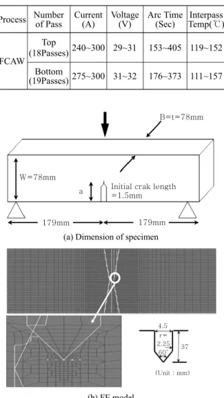
The FE model and mesh were determined to consider
the temperature distribution and stress variation, as
shown on Fig. 2, and an initial notch in accordance with
BS 7448 was inserted into the CGHAZ (Coarsened
Process Number of Pass Current
(A) Voltage(V) Arc Time(sec)
EGW (3G)
(1Pass) Top
400 42 1589
Speed
(cm/min) Interpass
Temp (℃) Heat Input (KJ/cm)
4.5 116 235.2
Bottom (1Pass)
Current
(A) Voltage(V) Arc Time (sec)
430 44 1310
Speed
(cm/min) Interpass
Temp (℃) Heat Input (KJ/cm)
5.5 162 206.4
Table 4 Welding condition for FCAW Process Number of Pass Current
(A) Voltage
(V) Arc Time
(Sec) Interpass Temp(℃)
FCAW Top
(18Passes) 240~300 29~31 153~405 119~152 Bottom
(19Passes) 275~300 31~32 176~373 111~157
179mm 179mm
Initial crak length
=1.5mm a
W=78mm
B=t=78mm
(a) Dimension of specimen
4.5
2.25 37 60°
(Unit : mm) r=
(b) FE model
Fig. 2 Dimension of specimen and FE model Table 3 Welding condition for EGW
Grain Heat Affected Zone) adjacent to the fusion line to estimate the quantitative toughness value around the fu- sion line.
2.2 Analysis method
In this study, the following three procedures for weld- ing heat conduct, residual stress and fracture analysis were carried out to examine the fracture toughness, K
IC, for a high strength ultra thick plate (EH36-TMCP) by each welding process, EGW and FCAW
14-20):
1) Analysis of heat conduct: Temperature distribution with time
2) Analysis of the welding residual stress: Thermal stress, residual stress and strain by the uneven tem- perature distribution
3) Analysis of the fracture behavior: Plain strain frac- ture behavior by the residual stress superposed with an external load
Unsteady state heat conduction and 2-D(two-dimen- sional) plane deformation thermal elastic-plastic analy- sis were carried out. Based on the results, to validate the numerical analysis result, X-ray diffraction was per- formed to examine the residual stress of the welded joints, and the results were compared with those of nu- merical analysis. The distribution of residual stress along the parallel to the weld zone in the weld was ana- lyzed at approximately 1 mm below the top surface and bottom of the weld specimen. A total of 370 points with a distance of 2, 3, 6, 18mm from the end of the welding bead were measured. FEM analysis of the fracture toughness, K
IC, for the welding region, where a bending force and the superposition with the bending and exist- ing residual stress have been applied, were considered to predict the fracture toughness by each welding proc- ess, EGW and FCAW, according to the change in a/W.
In accordance with BS 7448, the FE model was chosen to be same as the condition of the 3 point bending experiment. When external bending load was applied to the specimen, which was reflected the notch and initial crack on CGHAZ, the stress intensity factor at the ini- tial fracture point was analyzed to the specimen.
The crack-initiation point P
Qwas calculated from the load-clip gauge displacement curve, which was ob- tained from the 3 point bending experiment. The stress intensity factor K
Qwas calculated based on the calcu- lated P
Qas a crack-initiation point and after an assess- ment of the validity of K
Q, as described on (1), K
Qwas considered to be K
ICas the plain strain fracture toughness.:
B, α ≥ 2.5(K
Q/σ
y)
2(1)
The fracture toughness of the welding region was pre-
dicted according to the change in welding process. The
load P
Qat the crack-initiation point was calculated from
Ps, which has crossed between the OA', less than 5%
Force, P
θ
Clip gauge displacement,
V
gA′
Ps=PQ Pmax
0.95θ A
0
Fig. 3 Definition of P
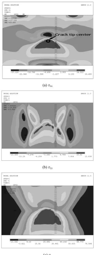
Q load at the crack-initiation point(a) σ
xx(b) σ
yy(c) σ
zzFig. 4 Welding residual stress profiles on the EGW welded
jointsfrom the liner gradient OA, and Ps on the load-clip gauge displacement curve as shown in Fig. 3. The load P
Qat the crack-initiation point in EGW and FCAW was 13,700Kgf and 13,900Kgf, respectively, when only a bending load was applied without welding residual stress. When the bending load and welding residual stress were applied, the loads to the crack-initiation point P
Qwere 12,500Kgf and 13,000Kgf in the EGW and FCAW, respectively.
3. Results and Discussions
3.1 Comparison of the residual stress in EGW and FCAW welded joints
The effects of the welding residual stress on the frac- ture behavior through the crack tip were examined by considering the characteristics of the distributed weld- ing residual stress via the crack tip in the EGW and FCAW welded joints. Fig. 4 shows the welding residual stress profiles obtained from two dimensional plane de- formation thermal elasto-plastic analysis on the EGW welded joints. The results showed that the magnitude of each welding residual stresses was in the following or- der: the welding residual stress in welding line direc- tion, σ
zz> welding residual stress in width direction, σ
xx> welding residual stress in thickness direction σ
yy. This result was caused by difference in mechanical restraints.
An examination of the welding residual stress showed that tensile σ
zz, compressive σ
xxand σ
yyoccurred on the front side weld and a large amount of compressive σxx was distributed at the center part of the specimen. In the case of backward welding, all stress components in the weld metal region showed tensile stress, particularly in the center part of the specimen. Moreover, the large σ
zz, appeared to exceed the yield stress compared to that of
the front welding due to the restraint by the former de-
posited welding i.e. front side welding. The maximum
stress σ
zz, produced on the center layer of thickness di-
rection was caused by high restraint, which was con-
centrated on the center layer due to the welding heat
input.
(a) σ
xx(b) σ
yy(c) σ
zzFig. 5 Welding residual stress profiles on the FCAW
welded jointsTo examine the effects of the welding residual stress to fracture behavior via the crack tip, the characteristics of the distributed welding residual stress via the crack tip in the EGW welded joints were investigated. A review of the welding residual stress in the width direction, which will exert fracture behavior, such as crack open- ing-closure on the crack tip, the tensile stress related to crack opening occurred on the crack tip. Therefore, this tensile stress can seriously affect crack opening, even crack propagation, without a further external load.
Fig. 5 shows the welding residual stress profiles on the FCAW welded joints. The magnitude of each welding
residual stress was in a similar order to that observed with the EGW welded joints. When the former de- posited weld was inputted by heat of later welding, the welding residual stress in the former weld region decreased. In contrast, the residual stress in the later welding part was increased by the restraint of the for- mer deposited weld. The maximum residual stress on the specimen surface was caused by a rapid temperature change due to heat transfer from the surface. A compar- ison of the welding residual stress by the welding proc- ess confirmed that the stress was due to the higher heat input in EGW.
Moreover, the tensile residual stresses to each direc- tion appeared to be higher in the EGW welded joints and were distributed more widely than that of the FCAW, and these trends were similar by way of the crack tips. Fig. 5 shows the welding residual stress on the crack tip of the FCAW welded joints. The welding residual stress examined in the width direction σ
xx. A compressive component was produced on the crack tip, which means that this compressive stress can help pre- vent or decrease the crack opening by closing the crack face, even if an external force is not loaded.A compar- ison of the characteristics of the distributed welding re- sidual stress through the crack tip by the welding proc- ess showed that the residual stress in the width direc- tion, σ
xx, in EGW welded joints, which is closely re- lated to the crack opening -closure behavior, was tensile residual stress on the notch tip, whereas that of FCAW was compressive residual stress.
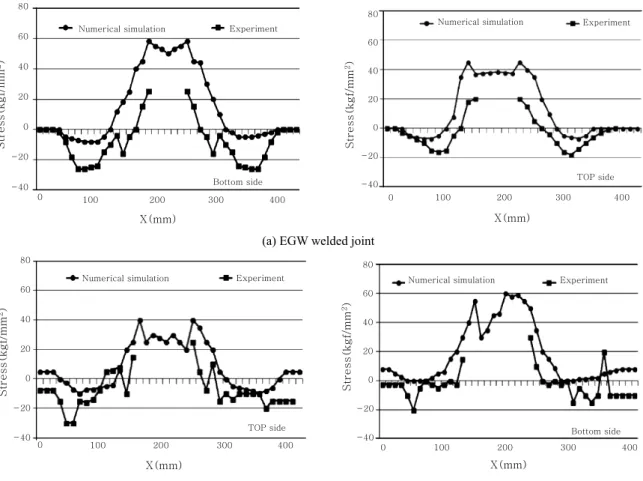
Fig. 6 shows the calculated values and experimentally measured values along the width direction at about 1 mm below the top surface and bottom of the weld specimen. The distributional aspects and the amount of stresses were consistent but the numerical results were slightly higher than the measured values. Conclusively, in qualitative aspect, the residual stress distribution showed similar characteristics.
3.2 Comparison of residual stress relaxation by notch effect in EGW and FCAW welded joints Similar to the 3-point bend test, a notch and initial crack was provided on the CGHAZ, on which the low- est toughness was observed, and the characteristics of the stress distribution around the notch and crack tip were examined when an external load was applied.
Welding residual stress distribution of the EGW and FCAW welded joints before notch preparation has been observed in Fig. 4 and 5 of previous section 3.1. This section intended to clarify welding residual stress dis- tribution of the welded joints after notch preparation.
Fig. 7 shows the residual stress distribution of the
Bottom side
X(mm)
0 100 200 300 400
-40 -20 0 20 40 60 80
Stress(kgf/mm2)
Experiment Numerical simulation
TOP side
X(mm)
0 100 200 300 400
-40 -20 0 20 40 60 80
Stress(kgf/mm2)
Numerical simulation Experiment
(a) EGW welded joint
TOP side
X(mm)
0 100 200 300 400
-40 -20 0 20 40 60 80
Stress(kgf/mm2)
Experiment Numerical simulation
Bottom side
X(mm)
0 100 200 300 400
-40 -20 0 20 40 60 80
Stress(kgf/mm2)
Numerical simulation Experiment
(b) FCAW welded joints
Fig. 6 Comparison of the welding residual stress values for EGW and FCAW welded specimen: (Left) top side, (Right)
bottom sideEGW and FCAW welded joints after notch preparation.
The distributions of the welding residual stress EGW welded joints were a tensile stress around the notch tip before providing a notch, but the distribution of all re- sidual stress components around the notch tip changed to a compressive residual stress after providing a notch, and this trend decreased gradually with increasing dis- tance from the notch tip. In particular, σ
xx, which is closely related to crack opening-closure, changed to compressive stress after providing a notch, whereas the tensile stress promoted a crack before providing a notch. As shown on these contours of the FCAW welded joints, σ
xxand σ
yyincreased and changed to compressive stress, respectively, while the tensile σ
zzdecreased.
In addition, compressive σxx, which is closely related to the retardation of crack opening, increased sharply after providing a notch.
3.3 Comparison of plain strain fracture toughness KIC in the EGW and FCAW welded joints Fig. 8 shows the fracture criteria for the crack-induced welding region by the welding process.
In contrast to the EGW, the fracture toughness of the FCAW increased at the superposition when the crack length was small, but this effect of the residual stress disappeared with increasing crack length. A welding structure is safe when the fracture toughness of that structure has a low value. The EGW is more vulnerable to crack propagation than FCAW because of the lower fracture toughness value than FCAW but as this differ- ence was not large.
4. Conclusions
1) Owing to the higher heat input in EGW, the tensile residual stresses to each direction were higher in the EGW welded joints and were distributed more widely than that of the FCAW, and these trends were similar through the crack tips.
The welding residual stresses(σ
xx) in EGW, which are closely related to the crack opening-closure behavior, showed tensile residual stress on the notch tip, whereas that of the FCAW showed compressive residual stress.
The distribution of residual stress through the crack tip
(a) σ
xx(b) σ
yy(c) σ
zzFig. 7 Welding residual stress distribution of the EGW and FCAW welded joints after notch preparation: (Left) EGW,
(Right) FCAWOnly load
a/w 820
860 880 900 920
840 KIC(kgf/mm1.5)
940
Superposition
0.4903 0.4936 0.4968 0.5128
Safety
Superposition Fracture
Fracture criterion
Only load
a/w
0.4968 0.5128 0.4936
0.4903 Superposition
Fracture criterion
820 860 880 900 920
840 940
Safety Only load
Superposition Only load
KIC(kgf/mm1.5)
(a) EGW welded joints (b) FCAW welded joints
Fig. 8 Comparison of the K
IC for welded specimens with various initial crack length to width ratiosmeans that a crack can be closed without an external force in FCAW, whereas the notch tip in EGW can be opened with that external load.
2) As the distributions of welding residual stress were changed when a notch was machined on the specimens, the contours of the residual stress(σ
xx) via the notch tip were changed to tensile from the compressive residual stress in the EGW, whereas the contour of the com- pressive residual stress(σ
xx) became larger than the ex- isting compressive residual stress.
Although the level of compressive residual stress(σ
xx) at the notch tip of the FCAW was lower than that of the EGW, the compressive residual stress in the FCAW was distributed more widely than that of the EGW.
3) A comparison of the fracture toughness KIC be- tween the EGW and FCAW welded joints showed that the K
ICof the EGW welded joint was lower than that of the FCAW. Therefore, crack propagation can occur easily in the EGW welded joint but this difference was not large.
Acknowledgement
This study was supported by research fund from Chosun University, 2013
References
1. Kim, C. G., A Study on the Trend and its limitation of building large container ship to reduce the logistics cost.
The Korean Association of Shipping and Logistics, (2002)
Han-Sur Bang got the Ph.D from Osaka
University, Japan, in 1990. His research field is welding mechanics(welding re- sidual stress and deformation) by FEM.He was invited professor in Osaka University and Harbin Institute of Tech- ology.
He won achievement award for Ppuri idustry policy from The MOTIE(Ministry of Trade, Industry and Energy) in 2013.
2. Minagawa, M, Ishida, K. et al., 390 MPa Yield Strength Steel Plate for Large Heat-input Welding for Large Container Ships. Nippon Steel Technical Report. 90 (2004), 7-10
3. Kim, C. M., Lee, J. B., Choo, W.Y., Characteristics of sin- gle pass welds in 50kJ/mm of heavy thickness shipbuild- ing steel. Proceedings of the Thirteenth International Offshore
and Polar Engineering Conference. (2003)
4. Jeong, H. C., Park, Y. H., An Y. H., Lee, J. B., Mechanical properties and micro structures of high heat input welded tandem EGW joint in EH36-TM Steel. The
Korea welding and joining society.25 (2007)
5. Inoue, T., Ishkawa, T. et al., Long Crack Arrestability of Heavy-thick Shipbuilding steels. Proceedings of the
Eighteenth International Offshore and Polar Engineering Conference. (2008), 132-136
6. Bang, H. S., Study on the mechanical behavior of weld- ed part in thick plate three-dimensional thermal elas- to-platic analysis based on finite element method.
Journal of the Korean Welding Society. 10 (1992), 37-43
7. Kim, Y. C., Yamakita, T., Bang, H. S., Ueda. Y.,Mechanical behavior on welding residual stress relief annealing of repair welding in thick plate. Q.J. Japan
Weld. Society. 6 (1988), 53-59
8. Ueda, Y., Kim, Y. C., Garatani, K., Yamakita, T., Bang, H. S., Mechanical characteristics of repair welds thick plate-distributions of three-dimensional welding re- sidual stresses and plastic strains and their production mechanisms, JWRI. 15 (1986), 359-368
9. Bang, H. S. , Kim, S. J., et al, Study on lamellar tearing generated by corner joint welding in box column of ul- tra thick plate. Science and Technology of Welding &
Joining. 6 (2001), 213-219
Hee-Seon Bang got the Ph.D from Osaka
University, Japan, in 2010. Her research field is welding mechanics(welding re- sidual stress and deformation) and weld- ing process (laser-arc hybrid welding and FSW).Recent researches focus on dissimilar fer- rous and non-ferrous materials joining. She is member of Ppuri industry development committee of MOTIE.