한국 CAD/CAM 학회 논문집
제 6권 제 3 호 2001년 9월 pp. 157-168 학술 논문
The Hierarchical Modeling Approach for Integrating the Enterprise Activity Model
•mn, H. B.* and Suh, H. W.**
*학생회원, 한국과학기술원 산업공학과
**종신회원, 한국과학기술원 산업공학과 - 논문투고일: 2000. 12. 18
-심사완료일: 2001. 5. 7
기업 액티비티 모델 통합을 위한 계층적인 모델링 접근법
전흥배
*
, 서효원**
ABSTRACT
The description of enterprise activities is the basis for process improvement and information system building. To describe such activities, it is necessary to model the enterprise activities from the abstraction level to the implementation level in a stepwise and integrated form. For this reason, several modeling approaches have been proposed. However, most of them lacked the stepwise or integration aspects although some of them covered overall levels. This study proposes the hierarchical modeling approach for integrating the enterprise activity model from the abstraction level to the implementation level sys
tematically. It is composed of five modeling levels such as function level, process level, task level, doc
ument workflow level, and event flow level. This study discusses the definition and characteristics of each level and compare our modeling frame with other modeling methodologies in case study.
Key words : Enterprise modeling, Function, Process, Task, Workflow
1. Introduction
An enterprise is composed of distinct activities exe
cuted by organized resources. These activities have complex interactions with each other for achieving business goals. The description of these interactions is the basis for analyzing enterprise activities and build
ing the information system. For this reason, the activ
ity model should be generated. This makes it possible to optimize organizational changes, store corporate knowledge, utilize process documents, and calculate the activity cost⑴.However, it is impossible to know the details of enterprise activities at the beginning of the system engineering because they have complex relations of various contents. Therefore, it is neces
sary to model whole enterprise activity step by step from the abstraction level of the enterprise to the implementation level of the individu지 operation.
Several researches propose their own modeling
architectures. However, previous researches lack the stepwise or integration aspects for the enterprise activity modeling. Also, several terminologies such as function, activity, action, process, task, operation, decision, procedure, scenario, worl^ow, and transac
tion are used without formal definitions. This causes many problems such as the ambiguity of semantics, modeling redundancy, and inconsistency among activ
ity models. To cope with these problems, it is impor
tant to construct the hierarchical level for the activity modeling.
In this study, we propose the hierarchical modeling approach for integrating the enterprise activity model.
For this purpose, we define: (1) the hierarchical struc
ture of five levels; (2) definition and characteristics of each level; for establishing and managing enterprise activities with a consistent view. Also, we compare our modeling frame with other modeling methodolo
gies in case study.
The contents of this paper are as follows: in the following section, previous researches are discussed and five levels for the enterprise activity modeling are discussed in section 3. In section 4, we describe a definition and characteristics of each level. In section
157
5, we introduce the case study.
2. Previous Researches
In general, enterprise modeling provides methods, tools, techniques, and a philosophy for describing and analyzing relevant aspects of the enterprise, and deriving a conceptual architecture^1. There are several modeling methodologies such as ARIS (ARchitecture for integrated Information System)[1,3,41, CIMOSA (CIM Open System Architecture)^* 81, IDEF (Inte
grated computer aided manufacturing DEFinitions methodology) series"」이, IE (Information Engineer
ing)14,11,12], IEM (Integrated Enterprise Modeling)[이, SADT (Structured Analysis and Design Technique)14,131, and Petri NetE4'7'14'l8].
The SADT proposes a construct, called actigram, for the activity modeling in software engineering141. It uses a modeling box and the ICOM (Input, Output, Control, and Mechanism) interface with the principle of the function decomposition.
The IDEF inherits the ICOM interface and the function decomposition from the SADT. Among sev
eral IDEF series, IDEFO and IDEF3 are closely related to the activity modeling. The IDEFO is a graphical method for modeling a system that is repre
sented by the function and their interfaces (ICOM)14,261.
On the other hand, the IDEF3 is designed for the description of how a system works1101, which is repre
sented by UOB (Unit Of Behavior), referent, links, and junction.
The CIMOSA provides a process oriented model
ing concept that captures both process functionality and process behavior4이. It has the hierarchical struc
ture for the activity modeling which is composed of enterprise domain, domain process, business process, enterprise activity, behavior rule, functional operation^
and functional entity. Tb represent the activity, it pro
poses the CIMOSA enterprise activity box with a
rectangle box and three pairs of input/output arrows for functions, controls, and resources141.
The IEM combines various features from previous approaches for the activity modeling such as the ICOM box (IDEFO), behavioral rules (CIMOSA), and the ICOM interface (object-oriented approach)囲,It separates the enterprise model into just two main views: function and information. In the function view, it has three modeling levels such as action, function, and complete activity, represented by a generic con
struct and a process, called GAM (Generic Activity Model) and activity chain, respectively.
The Petri net is a bipartite directed graph com
posed of two types of nodes: places and transitions, connected by directed arcs. It is a suitable diagram for the activity modeling of the low level because of handling of dynamic aspects with tokens. Recently, its effectiveness as the workflow modeling tool has been recognized by several researchers115J7].
The ARIS has four views (junction view, data view, organization view, and control view) and three system development steps (requirements definition, design specification^ and implementation description) for the enterprise modeling⑶.Among four views, the function view and the control view are related with the description of the activity flow. For this, VAC (Wlue Added Chain), FFD (Function Flow Diagram), and EPC (Event Process Chain) are mainly used.
The IE is the enterprise modeling methodology that has five system development phases: ISP (Information Strategy Planning), BAA (Business Area Analysis), BSD (Business System Design), and C&T (Construc
tion and Test). It separates the enterprise modeling into two parts: data modeling and process model- ing[iI]. The process modeling has hierarchical levels for the activity modeling such as function, process, activity, and procedure. It mainly uses the decomposi
tion diagram and the dependency diagram* 121.
As mentioned earlier, each methodology has the Table 1. Hierarchical structure of previous modeling methodologies in the activity modeling viewpoint
Modeling level Modeling Level Focus Diagram Focus
CIMOSA IE IEM-GAM ARIS SADT/IDEF Petri net
High (Concept)
-Domain process -Function -Action -VAC1 -Context diagram -IDEFO
Intermediate (Activity flow)
-Business process -Enterprise activity
• Process -Activity -Procedure
-Function -Complete
activity
-FFD2 -EPC3
-IDEFO -IDEF3
-High Level Petri net -Petri net Low
(Implementation)
-Functional operation
-EPC -OSTN -Petri net
'VAC (Value Added Chain), 2FFD (Function Flow Diagram), 3EPC (Evst Process Chain).
한국CAD/CAM학회 논문집 제 6 권 제3 호 2001년 9월
기업 액티비티 모델 통합을 위한 계층적인 모델링 접근법 159
Table 2. Comparison of previous modeling methodologies in the activity modeling viewpoint
Criteria SADT IDEF CIMOSA IEM Petri net ARIS IE
Semantics + + A A + + △
Hierarchic이 levels of the activity modeling △ A A A - △ A
+: Formal definition, Does not exist, △: Poor definition.
activity modeling architecture with its own viewpoint.
Table 1 shows this with focusing on the modeling level and diagram techniques. Also, table 2 shows comparisons of previous methodologies with several criteria such as semantics and hierarchical levels for the activity modeling. As shown in table 1 and table 2, previous methodologies have some limitations.
First, they have limitations in the stepwise modeling of whole enterprise activity with the consistent view.
For example, in case of ARIS, ARIS KOBE (House Of Business Engineering)"' for the process manage
ment, does not support a concrete modeling level. In the SADT/IDEF, although a user can decompose an activity arbitrarily, they lack the hierarchical modeling structure. Also, the Petri net has a similar problem although the high-level Petri netsE16,I8] such as colored Petri nets and hierarchical Petri nets are proposed to overcome the limitation in describing the high level.
Tb solve these problems, we propose the hierarchical structure of five levels for whole enterprise activity modeling.
Secondly, some of them have the limitation in modeling the detailed implementation level. For example, the SADT/IDEF have limitations in describ
ing dynamic behaviors such as event and condition.
Also, the IEM does not provide a description model for an implementation level although it can be applied to system requirement definition and design specification^1. In addition, the IE has the limitation in describing dynamic behaviors with its diagrams.
For these points, our hierarchical structure considers the detailed implementation level describing dynamic behaviors.
Finally, many methodologies have ambiguous defi
nitions of modeling semantics so that designers would have difficulties in modeling the enterprise activity.
Schlenoff et <江."이 say that existing approaches for process modeling lack an adequate specification of semantics of the process terminology, which leads to inconsistent interpretations and uses of information.
Table 2 shows that some methodologies such as the IE and the CIMOSA圓 have poor definitions of semantics in the activity modeling viewpoint, lb address this point, we describe explicit semantics for
the activity modeling of each level.
3. The Hierarchical Structure for the Enterprise Activity Modeling
As shown in Fig. 1, we propose the hierarchical structure of five activity levels: function, process, task, document workflow, and event flow. It enables design
ers to connect defining enterprise activities to build
ing the information system smoothly with a consistent view. The function, the process, the task, and the document worl^ow level can be used for understanding and refining the flow of the enterprise activity step by step. On the other hand, the event flow level can be used for providing a map for exe
cuting activities automatically. This hierarchical struc
ture provides the basic frame for supporting stepwise modeling of whole activity.
The five levels are needed for following reasons.
As the first step for modeling the enterprise, it is necessary to know the scope and structure of the enterprise because they provide designers with the modeling frame of the enterprise. The activity model
ing level for this is called the function in this study.
After defining the function of the enterprise, it is nec
essary to grasp the main flow of the enterprise activ
ity. This could be done through defining the chain of activities that have the data dependency relation. The process level has this role. As decomposing the pro
cess in detail, it is necessary to decide to what extent the process should be decomposed. It can be deter
mined by the characteristics of the output of an activ
ity. We consider the process that produces a single document as an elementary one, and define it as the task. The relations among elementary processes are designed at the task level. The single document can have concrete and several forms such as the elec
tronic file, the hard copy, the screen shot, the email, and so on. It is useful to model the activity based on characteristics of its output when modeling the enter
prise activity. Especially, regarding the process pro
ducing only single document as the elementary process can guide us to decide what the elementary process is. Also, this can provide us with process
한국CAD/CAM학회 논문집 제 6 권 저】 3 호 2001년 9월
models of same level of abstraction.
If the single document is not made by one person, rather several persons, its generation flow should be defined. For this reason, the document workflow level is proposed. At the document workflow level, the static flow of generating the single document is designed. However, their dynamic behaviors should be defined for implementation. They are designed at the event flow level.
As stated above, each level has its distinctions from other levels. However it is based on the upper level. Eventually, this hierarchical structure of five levels leads designers into smooth top-down model
ing. On the other hand, this structure provides the basic frame of bottom-up information gathering for the activity management in the integration aspect.
Because interests of managers are not only various according to their position but also related with each other, from the top management level to the imple
mentation level, it is necessary to construct the hier
archical structure of activity model that can integrate the activity information. In general, there are three types in the enterprise activity according to its nature:
material processing, information processing, and busi
ness processing1201. Among them, information and business processing activities use a business document as a common media for a business transaction^11.
According to the degree of the abstraction, it has sev
eral types. In ours, four levels, except the function level, have specific output types as shown in Fig. 1.
The process level has a documents packet as an out
put type, which is generated by the aggregation of several outputs of sub-levels. At the task level, a sin
gle document is an output type, which is generated by going through several outputs of the document workflow level; intermediate documents such as a created document, a reviewed document, and an approved document. The intermediate document is generated by triggering of the event, an output type of the event flow level. Also, from the task level to the function level, each has an inherent goal that is driven by that of the parent. The goal is evaluated by outputs of each level except the junction level. The goal of the junction level is achieved by goals of the process level. Eventu지ly, five levels are closely related with each other by linkages of outputs and goals as shown in Fig. 1. These links provide manag
ers with the hierarchical structure for the activity management and improvement through bottom-up information gathering. Based on these links infonna- tion, we can plan the activity schedule, or monitor the status of the activity, or evaluate the performance of the activity with the integrated view.
4. Definition of the Hierarchical Structure with Five Levels
4.1 Function Lev이
This level defines the scope and structure of the enterprise, i.e. the relations of functions. Maitin[12]
previously defined the function as “a group of activi
ties which together support one aspect of furthering the mission of the enterprise". ARIS⑶ defined it as
^operations applied to objects for the purpose of sup
porting one or more goals'*. In this paper, the func
tion is defined as "the group of static activities that
Information Gathering
Function Horirontal Relation
(Not exist/
応;浦"
(a) Distinctions amongfive levels Document type Process (Document packet/
Single document)
Actor size (Non-single/
/ Task
Act 或type (Human/
丿/Document Workfl 0吃/"
Human or System)
Event flow
_/
(b) Output relations among five levels
Fig. 1. Five modeling levels for whole enterprise activity modeling.
Stepwise Modelin。
한국CAD/CAM학회 논문집 제 6권 제3 호 2001년 9월
기업 액티비티 모델 통합을 위한 계충적인 모델링 접근법 161
have the common goal of organizations^. We can see the structure of the enterprise and its operation envi
ronment, i.e. the scope, the role, and the objective of organizations, through defining the Junction. Thus, at defining the function, it is important to know how to group the activities and wh저 its goal is because it is closely related to restructuring of organization such as new grouping of activities, the elimination of unnec
essary activities or the addition of new activities due to the change of the environment. However, it is not easy for the consultant to understand the enterprise functions at a glance. In general, it is possible to define the function of an enterprise with the organiza
tion chart since defining the function is closely related with the role assignment of the organization.
In ARIS"‘지, the term function is not defined gener
ically. But it is used synonymously with the terms:
the process, the activity, or the task. However, in this study, the function is distinguished from others in several aspects. Table 3 shows general characteristics of the function. First, it is organization oriented because defining the function depends on the organi
zation structure. Second, the type of its name should be a noun or a gerund, since a Junction categorizes what is done, not how[l2]. Third, the actor that per
forms the function may be a relatively large unit such as the department of an enterprise. Finally, it does not have the explicit horizontal relation because it focuses on not relations with others but static aspects of the enterprise. However, it has the hierarchical relation with others because it is decomposable itself.
The decomposability gives us a more flexible view by allowing modeling of a system at a certain abstraction level. Also, it has the vertical relation
Table 3. The characteristics of five modeling levels
Criteria Function Process Task Document
workflow Event workflow Characteristics Organization oriented Artifact oriented Behavior oriented
Focus What How/Who Event/Condition/Action
Actor Department unit Department or team unit Person unit System module Horizontal relation Dont exist Dependency
relation Precedence relation
Output Goal Information
(Document packet)
Sin 이 e document
Intermediate
document Event
Decomposition Decomposable Not decomposable
Vertical relation Exist
njd:ActivityName
Actor Name
(a) Activity model construct
Intennediate D ocxinwnt
(b) Data symbols
D efiendency relation
Precedence relation
(c) Relation symbols (d) others
Fig. 2. Symbols for the activity modeling.
Fan-In, Asynchronous Fan-Out, Asynchronous Loop operator: Fan-In, Asynchronous
应
Fan-In, Synchronous Fan-Out, Synchronous Loop operator Fan-In, Synchronous
(e) Operator types
한국CAD/CAM학회 논문집 제 6 권 제3 호 2001년 9월
Parent ID
Actor Nune
Pjd Name ActaN amt
1
Pjd:Hams Fjd. Name
ActorName ActorName
(a) Function Model (b) Function Decomposition Diagram
Fig. 3. Diagrams of the function level.
enterprise function, the function decomposition dia
gram is adopted. Fig. 2 describes symbols for the activity modeling and Fig. 3 describes diagrams of the function level.
4.2 Process Level
It is the modeling level for grasping the main flow of the enterprise activity, i.e. the relations of pro
cesses. A process was defined as “a set of one or more linked procedures or activities that collectively realize a business objective or policy goal[22],\ In this paper, it is defined as '"the activity that has the data dependency with others for achieving the specific goar. The function informs us role aspects of organi
zations of the enterprise, but the process informs us procedural aspects of a specific action that has defin
able beginning and ending points[12]. In general, the enterprise has the data dependency with external environments by external inputs. Thus, listing external inputs enables designers to understand the main flow of the enterprise activity.
As shown in table 3, the pivcess has several inher
ent characteristics. First, whereas a function is organi
zation oriented, the process is data oriented because it has inputs and/or outputs. Second, it is not mainly concerned with what has to be done, rather how or by whom it is done. Therefore, the type of its name is a verb[12]. Third, the actor that carries out the pro
cess may be a smaller unit than that of the Junction, such as a team or a department of the enterprise.
Fourth, there exists a data flow between processes, which makes the horizontal relation. There is a pre
cedence relation at the low level of the process.
However, the top level has a dependency relation because it is difficult to know the ordered sequence due to its abstract outputs that occur m니tiple rela
tions. The horizontal relation is the key issue of mak
ing the process different from the Junction. If there
(a) Process model
(b) Process Decomposition Diagram
Fig. 4. Diagrams of the process level.
exists the explicit dependency relation when decom
posing the functions, then, the function of this decomposition level can be defined as the process.
Finally, it has the vertical relation with the task. In addition, the process is also decomposable itself. To represent horizontal and vertical relations, the process dependency diagram and the process decomposition diagram can be used as shown in Fig. 4, respectively.
4.3 Task Lev이
The main purpose of this level is to model the flow of activities that generate the single document. It is represented with relations between the task and the operator. A task was defined as "a collection of operations that corresponds to a step in a common business process⑵]" or "some work to be done and can be specified in a number of ways, including a textual description in an email message, or a com
puter programr23],\ In this study, the task indicates
"'the elementary activity that produces a single docu
ment for achieving its own goaV. It is an elementary process that corresponds to the bottom node of the process decomposition diagram. The output of the task should be only a single document although sev
eral documents can be used as its inputs.
At this level, it is necessary to represent the path control of the document with an operator. According to the control type, the direction of the flow, and the synchronization type, the operator is classified as fol
lows: Single relation, Selective choice, and Loop;
Fan-in and Fan-out; Asynchronous and Synchronous, respectively. Their graphical notations are shown in Fig. 2(e). The single relation means one to one rela
tionship between activities, which does not need the operator. The selective choice operator (成)selects k
한국CAD/CAM학회 논문집 제 6 권 저I 3 호 2001년 9월
기업 액티비티 모델 통합을 위한 계층적인 모델링 접근법 163
routes among n paths with the merging and branch
ing rule 잔 multiple relations. Simply, only one selec
tion GS) and all selections (“£) are the same as XOR (exclusive OR) and AND of the IDEF3, respectively. The loop operator is for a feedback operation and others are same with those of the IDEF3. At this level, simple operators that have the role of XOR or AND are used frequently.
Table 3 shows several characteristics of the task.
First, it is data oriented and focuses on how or by whom the task is done, like the process. Second, an actor that carries out the task should be an individu지 or identifiable members because a sin이e document is generated by the assigned member(s). Third, it has the horizontal (precedence) relation with others because it can be represented in the form of logically ordered activity sets due to the concrete and the explicit out
put type (single document). Also, it has the vertical relation with the activity of the document workflow level. However, it is not decomposable itself. Ib rep
resent the precedence relation among tasks, the task precedence diagram can be used as shown in Fig. 5.
4.4 Document Workflow L取이
It is for modeling the lifecycle of generating the single document. This level is composed of relations between the document lifecycle activity and the oper
ator. If a single document is generated by several people (called workflow participants^1'''), the document workflow that indicates a well defined flow of docu
ment lifecycle activities for supporting the task to be executed should be designed. The document lifecycle activity means "the document operation for complet
ing the single document such as creation, review, update, approval, and distributM'. In general, the
document is passed through several people that have different authorizations on the document such as cre
ate, read, write, delete, and baselin^24}, due to their position of the organization. Therefore, to design the document workflow it is necessary to allocate an appropriate document lifecycle activity to an appropri
ate actor with assigning a proper authorization of the document.
At this level, the operator is also used for repre
senting the document lifecycle flow. However, unlike the task level, the loop operator may be frequently used because the document workflow has many feed
backs. Also, the selective choice operator may be fre
quently used for selecting several alternatives due to dynamic resource allocations.
Table 3 shows several characteristics of the docu
ment lifecycle activity. First, it focuses on not the data but the control of the document flow. Thus, it is behavior oriented because the document workflow is not generally fixed but can be changed by several circumstances such as a change of the resource schedule and the occurring of the exception case.
Second, an actor that performs the document lifecycle activity should be an individual person. Third, it has the horizontal (precedence) relation. Also, it has the vertical relation with the activity of the event flow level. However, it is not decomposable itself. Fig. 6 describes diagrams of the document workflow level.
4.5 Event Flow Lev이
This level focuses on the dynamic aspects, i.e.
dynamic behaviors, for supporting the generation of a single document, whereas the document workflow level focuses on the static structure for the document flow, composed of activities, document, actor, prece
dence arc, and routing operator object. Each object
(a) Task Model
I PaientlD
-一r
I Donun.nl ~i |
卸 O三+^饗급프니上^^ 曲
YhJd Actor 너lewDonunenl Nuns mute(b) Task Precedence Diagram
Fig. 5. Diagrams of the task level.
(a) Document WorkflowActivity
(b) Document WorkflowDiagram
Fig. 6・ Diagrams of the document workflow level.
한국CAD/CAM학회 논문집 제 6 권 제3 호 2001년 아월
(a) State transition of unit activity of the procedure
I Acn 햐y ] Start, Runmikg, Cmplcte
<=
<=>
[二H歸可 「寻;版蚯
,허航前谙4
(b) Relation of state values between acti머ty and others
Fig. 7. Representation of dynamic behaviors.
has the state value that is varied dynamically over time.
For example, a document may be available, or not available due to being updated by another activity, not being generated, and so on. An actor may be available, or not available due to several reasons such as absence, a business trip, and so on. Also, the route between activities, combination of precedence arc and routing operator object, may be reliable, or not reli
able due to several communication problems. Also, the activity can have several states according to the combination of states of above objects as shown in Fig. 7(a). If all states of other objects are available and reliable, the activity can work normally from starting to completion, otherwise, the activity does not start or stops the execution temporally or perma
nently. Fig. 7(b) describes the typical relations between the activity state and combinations of states of others.
In addition, there exist many cases of the relation between them. If the system state is considered for supporting the document worlrflow automatically, there exist a large number of cases. Anyway, for each case, it is necessary to describe dynamic behav
iors, i.e., the triggering rules on changes of state val
ues of these objects.
한국CAD/CAM학회 논문집 제 6권 제3 호 2001년 9월
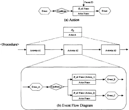
Dynamic behaviors can be described by three enti
ties (ECA[3,241): the event, the condition, and the action. The action means "cm activity that a user or the information system takes due to the change of the state value^ i.e. event occurrence, under a predefined condition". If a specific event occurs due to the change of the state, then, the corresponding action is performed, followed by a response event that stimu
lates other actions. The condition constructs triggering relations between events and actions. The triggering relations are represented by the rule descriptions in this study.
As shown in Fig. 7(a), due to the transition type of the activity states, characteristics of triggering rela
tions can be classified into three parts: control, rout
ing, and exception handling. Therefore, there are rule descriptions with respect to the control^ the routing, and the exception handling. The control rule is used to describe the general triggering relation, from start to running and from running to complete. The rout
ing rule is needed to handle routing logic between activities. Also, it describes branching rule and merg
ing rule of an operator. The exception handling rule is used to handle the exception case, i.e. transition to suspended or abort state, due to the system shut
기업 액티비티 모델 통합을 위한 계층적인 모델링 접근법 165
down, the absence of the person in charge, and so on. In each rule description, request events, corre
sponding actions, and response events are listed up under a specific condition as shown in Fig. 7(c).
Eventually, dynamic behaviors of the document work
flow are represented with the network of unit actions triggered by predefined conditions^ whenever events occurring. It is called the event flow diagram. Fig.
7(c) indicates that the graphical representation of the rule descriptions is the event flow diagram.
In this study, the event flow diagram is based on the unit activity of the procedure of each document lifecycle activity. The procedure means the sequence of detailed activities for achieving a document lifecy
cle activity. Because it is difficult to describe the dynamic behaviors of the document workflow activity directly due to its complexity, the procedure is used.
For example, creating a document activity (document lifecycle activity) may have the procedure, composed of sequential activities as follows: opening a standard document, referring other data, writing the contents in the document, saving the document, and so on.
The dynamic behaviors of opening a standard docu
ment activity can be described as the combination of events, conditions, and actions such as document searching, document selecting, document loading from a database, and so on. Dynamic behaviors of creat
ing a document activity can be described with the set of those of each activity of the procedure.
Table 3 also shows several characteristics of the action. First, similar to the document lifecycle activity, it is behavior oriented. Therefore, it focuses on not what or how/who rather the dynamic behaviors of the document workflow. Second, its actor type is an indi
vidual or a system module. Finally, the action has the horizontal (precedence) relation. Also, it has the vertical relation with the document lifecycle activity.
However, it is not decomposable itself. Fig. 8 describes diagrams of the event flow level.
5. Case Study
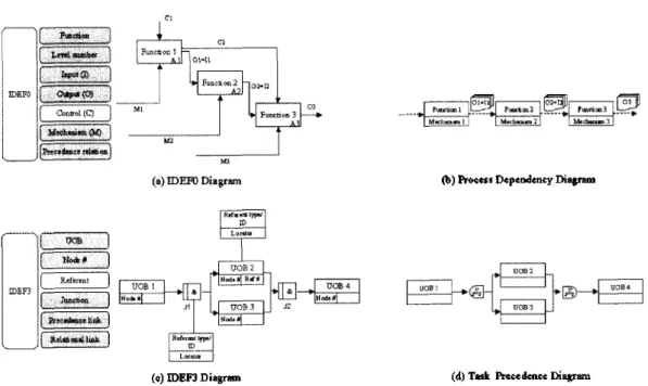
In this section, we compare major modeling meth
odologies such as IDEF and ARIS with ours. Fig. 9- 10 show the comparison of the modeling components between them. The shaded boxes indicate modeling components of compared diagrams that can be replaced with those of ours directly.
The modeling level of the IDEFO diagram is equivalent to the process level of ours because the function of the IDEFO diagram has a data depen
dency. Most modeling components of the IDEFO can be replaced with those of ours as shown in Fig. 9.
However, Control is not graphically represented in the
(a) Action
Fig. 8. Diagrams of the event flow level.
한국 CAD/CAM학회 논문집 제 6 권 제 3 호 2001년 陋
(b) Process Dependency Diagram
(c) IDEEJ Diagram (d) Task Precedence Diagram
Eg航言云*島허
厂
겨 g )Fig. 9. Comparison of modeling components between the IDEF methodology and ours.
(c) Function How Diagram
(b) Process Dependency Diagram
FuDCtionl
FuncticiiS
□rgnucelion
(d) Task Precedence Diagram
(c) Event Access Chain Ehagram
Fig. 10. Comparison of modeling components between the ARIS methodology and ours.
diagrams. But its concept is partially included in the constraint attributes and the goal attribute.
The modeling level of the IDEF3 is equivalent to the task level of ours because it handles the control of the flow with Junction. Thus, the IDEF3 can be replaced with the task precedence diagram of 이hs
directly as shown in Fig. 9. However, the Referent component for making a reference to other objects is not supported in ours.
Fig. 10 아lows major diagrams of the ARIS meth
odology such as VAC, FFD, and EPC. The VAC is used to describe the relation between Junctions of an
한국CAD/CAM학회 논문집 제 6 권 제3 호 2001년 9월
기업 액티비티 모델 통합을 위한 계충적인 모델링 접근법 167
enterprise at the initial modeling. Therefore, the VAC corresponds to the top of the process level of ours and can be replaced with the process dependency diagram because most modeling components of the VAC can be replaced with those of ours directly except Cluster. Cluster may be replaced with Data store of the task precedence diagram but it is not considered at a somewhat abstracted level such as the process level.
The FFD corresponds to the task level of ours because it can represent the precedence relation with the operator. Thus, the FFD can be replaced with the task precedence diagram of ours directly. Also, the EPC corresponds to the event flow level of ours. It can be replaced with the event flow diagram because it can handle the dynamic behavior with the event triggering. Most of modeling components except Message and Operator can be replaced with those of the event flow diagram. Although Message and Oper
ator are not supported explicitly but attributes of trig
gering condition and the Condition may play similar roles such as asking the successor to start the activity and routing the activity flow, rcspectiv이y.
Through the comparisons of major modeling meth
odologies with ours, we can see several advantages of ours in whole enterprise activity modeling. First, ours can cover most of modeling area and components of IDEF and ARIS although some modeling components are not supported fully. On the other hand, the IDEF methodologies have the limitation in representing the low level activities that have the iterative and dynamic characteristics although the IDEF3 can rep
resent the iterative work with the XOR junction.
Second, ours has the consistent modeling viewpoint among diagrams. Our diagrams consider data flow and actor information through modeling levels. However, the IDEF has a weak cohesion among their diagrams [25]. For example, the IDEF3 does not represent the data flow explicitly while the IDEFO does. Also, IDEFO considers the actor information but IDEF3 does not explicitly. In the ARIS, the VAC and the FFD consider actor information but the EPC does not. These give rise to the difficulty of modeling whole enterprise activity systematically.
Finally, ours reduces the ambiguity of the activity modeling through the stepwise modeling with explicit semantics. The connection and distinction among activity modeling levels are more explicit than others because we divide the activity level due to several characteristics, especially, the type of outputs. This provides us with more clear semantics and helps us
to reduce the ambiguity of the modeling.
6, Conclusion
This paper proposes the hierarchical modeling approach for integrating the enterprise activity model.
To model from the highest abstraction level to the lowest implementation level systematically, the five modeling levels are defined, and their characteristics are also discussed. Also, comparisons of other model
ing methodologies are introduced in the case study.
The hierarchical modeling approach makes it possible to model the enterprise activity in the stepwise pat
tern. The fact that each level is based on the upper level, makes it possible to integrate wh이e enterprise activity. Although there exists the subjective charac
teristics of the modeling, the formal definition of each level enables us to design, analyze, and control enterprise activities in the consistent view. Also, it promotes the complete understanding of activity behaviors so that time and cost can be saved in the system engineering.
This research can be extended to several directions.
For example, one may construct concrete modeling procedures for whole enterprise activity. Also, detailed descriptions of activity schema of five levels and then- relations may be needed. In addition, the activity modeling can be supported by developing the com
puter aided tool that has the graphical and the syn
tax-driven editors.
Reference
1. Scheer, A.-W., ARIS-Business Process Framework, Second, Completely Revised and Enlarged Edition, Springer, 1998.
2. Ngwenyama, O. K. and Grant, D. A., "Enterprise modeling for information systems architectures: An object-oriented approach/' Computers and Industrial Engineering, Vol. 26, No. 2, pp. 279-293, 1994.
3. Scheer, A.-W., ARIS-Business Process Modeling, Sec
ond, Completely Revised and Enlarged Edition, Springer, 1998.
4. Vemadat, F. B., Enterprise Modeling and Integration:
Principles and Applications, Chapman & Hall, First edition, 1996.
5. ESPRIT Consortium AMICE (Eds.), Open System Architecture for CIM, Research Reports, ESPRIT, Project 688, AMICE, Vol. 1, Springer-Verlag, 1989.
6. Kosanke, K. et al., "CIMOSA: enterprise engineering and integration," Computers in Industry, Vol. 40, pp.
83-97, 1999.
한국CAD/CAM학회 논문집 저] 6 권 제 3 호 2001년 9월
7. Aguiar, M. W. C. and Edwards, J. M., "Achieving manufacturing business integration through the com
bined formalisms of CIMOSA and Petri nets," Inter
national Journal of Production Research, VbL 37, No.
8, pp. 1767-1786, 1999.
8. Bruno, G. and Agarwal, R., "Modeling the Enterprise Engineering Environment,M IEEE Transactions on Engineering Management, Vol. 44, No. 1, pp. 20-30, February, 1997.
9. Mayer, R. J., IDEFO Function Modeling, Knowledge Based Systems, Inc., 1994.
10. Mayer, R. J. et al., Information Integration for Con
current Engineering (IICE)-The IDEF3 Process Description Capture Method Report, Knowledge Based Systems, Inc., 1995.
11. Martin, J., Information Engineering, Book I: Introduc
tion, Prentice-Hall, Inc., 1990.
12. Martin, J., Information Engineering, Book II: Planning and Analysis^ Prentice-Hall, Inc., 1990.
13. Marca, D. A. and McGowan, C. L., Structured Analysis and Design Technique, McGraw-Hill Book Company, 1987.
14. Peterson, J. L., Petri Net Theory and the modeling of systems, Prentice Hall, Inc., 1981.
15. Adam, N. R. et al., "Modeling and analysis of work
flows using Petri nets," Journal of Intelligent Infor
mation Systems, Vbl. 10, pp, 131-158, 1998.
16. van der Aalst, W. M. P. and van Hee, K. M., "Business process redesign: A petri-net-based approach/' Com
puters in Industry, Vbl. 29, pp. 15-26, 1996.
17. Bupler, C., ^Specifying Enterprise Processes with Workflow Modeling Languages,,5 Concurrent Engi
neering: Research and Applications, Vbl. 4, No. 3, pp. 261-278, 1996.
18. Gruhn, V., "Business Process Modeling and Workflow Management," International Journal of Cooperative Information Systems, Vbl. 4, No. 2&3, pp. 145-164,
1995.
19. Schlenoff, C. et al., "The Process Specification Lan
guage (PSL) Overview and Version 1.0 Specification,"
In the NIST Internal Report (NISTIR) 6459.
20. Medina-Mora, R. et al., "The Action Workflow Approach to Workflow Management Technology,M In the CSCW 92 Proceedings^ November, 1992.
21. Kumar, A. and Zhao, J. L., "Dynamic Routing and
Operational Controls in Workflow Management Sys
tems/
* Management Science, Vbl. 45, No. 2, pp. 253- 272, 1999.
22. Workflow Management Coalition Work Group 1,
"Workflow Management Coalition Interface 1: Process Definition Interchange Process Model/' In the Docu
ment Number WjMC TC-1016-P, Document Status- 7.05 beta, 1998.
23. Cichocki, A. et al., Workflow and Process Automation:
Concepts and Technology, Boston: Kluwer Academic Publishers, 1998.
24. Intergraph, AIM/Wbrkflow Administrators Guide, ver
sion 2.2, March, 1997.
25. Herbst, H. et al., "The Specification of Business Rules:
A Comparison of Selected Methodologies,5, Published in A. A. Verijn-Stuart, T. W. Olle (Eds.), Methods and Associated Tools for the Information System Life Cycle, Amsterdam et al.: Elsevier, pp, 29-46, 1994.
26. 황호진, 이수흥, “STEP을 이용한 프로세스 표현에 관 한 연구,'' 한국 CAD/CAM 학회 논문집, 제4권, 제4 호, pp. 371-380, 1999.
전 흥 배
1995년 연세대학교 웅용통계 학과 학사 1997년 한국과학기술원 산업공학과 석사
199湼~현재 한국과학기술원산업공학과박
사과정
관심분야: Concurrent engineering strategy, Enterprise activity modeling, Model
ing and performance evaluation of product development process
서 효 원
1981 년 연세대학교 기계공학과 학사
1983년 한국과학기술원 기계공학과 석사 19이년 West Wginia Univ. 산업공학과
박사
1992년~1995년 생산기술연구원 (KATTECH) 생산시스템개발센터수석연구원 1996년〜현재 한국과학기술원 산업공학과부
교수
관심분야: Concurrent engineering, CIM, Product development management
한국CAD/CAM학회 논문집 제 6 권 저13 호 2001년 9월