한국추진공학회 2011년도 춘계학술대회 논문집 pp.371~374 2011 KSPE Spring Conference
- 371 -
이중연소 램제트 엔진의 난류 연소 현상과 화염 안정성
최정열* ․ 한상훈** ․ 김규홍***
Numerical Study of Flame Stability of Turbulent Combustion in a Dual Combustion Ramjet
Jeong-Yeol Choi* ․ Sang-Hoon Han** ․ Kyu-Hong Kim**
ABSTRACT
High-resolution numerical study is carried out to investigate the flame stability of the turbulent supersonic combustion in a Dual-Combustion Ramjet (DCR). The auto-ignition in a shear layer between hydrogen/carbon-monoxide syngas and air was studied at elevated enthalpy condition. Comparison of a constant area combustor and a combustor with a small divergence angle shows that the supersonic combustion has a characteristics of the lifted flame and its stability is influenced significantly by the compressibility.
초 록
이중연소 램제트 엔진의 초음속 난류 연소의 화염 안정성을 살펴보기 위하여 다차원 외삽을 이용한 고해상도 전산 유체해석을 수행하였다. 높은 엔탈피 조건의 수소/일산화탄소 합성 가스와 초음속 공 기의 전단층 내 자발 점화를 살펴보았으며, 일정 단면적 연소기와 작은 확산각이 있는 초음속 동축 연 소기에 대한 비교를 통하여 초음속 연소는 부상 화염의 특징을 보이며 화염 안정성이 압축성 효과에 크게 영향 받음을 알 수 있었다.
Key Words: Dual Combustion Ramjet(이중 연소 램제트), Syngas(합성가스), Lifted Flame(부상 화 염), Compressibility Effect(압축성 효과)
* 부산대학교 항공우주공학과 ** 항공우주연구원
*** 서울대학교 기계항공우주공학부 교신저자, E-mail: [email protected]
Hybrid RANS/LES study is carried out for a combustion flow field of supersonic coaxial fuel and air flows at elevated enthalpy condition. It is to understand the flame
structure and dynamics of supersonic combustion in dual combustion ramjet (DCR) engine.[1] The flowfield is assumed to be axi-symmetric for computational efficiency.
Species conservation equations for eight reacting species (O, O2, H, H2, OH, H2O, CO, CO2) and inert assumed nitrogen (N2) are considered with momentum and energy
- 372 -
T (K) P (bar) Composition
Air M=2.0 1,200 K 1 bar O2+3.76N2
Fuel M=1.0 1,200 K 2 bar CO+H2
Grid 2,201x201(main combustor) + 81x81(Air intake) + 61x61 (fuel nozzle) Comp. Cond. 1”=2.54 cm, Prt=0.9, Sct=0.4, MLP
Table 1 Flow conditions for the supersonic combustion flow field in DCR.
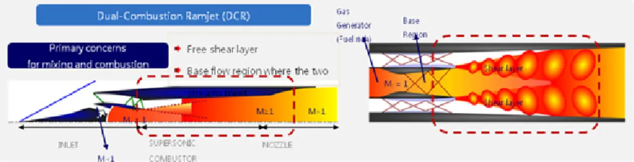
Fig. 1 Schematics of the flow features in a Dual Combustion Ramjet (DCR) and the supersonic combustion flow field in DCR
Fig. 2 Computational domain of the supersonic combustion flow field in DCR: (upper) model combustor 1 with constant area duct followed by a diverging duct, (lower) model combustor 2 with divergent duct.
equations. Two-equation Menter's shear stress transport (SST) model is used with SST DES (detached eddy simulation) extension to enhance the eddy capturing characteristics at separated flow region while preserving the RANS characteristics at boundary layer.[2]
Convective flux vector are discretized by the Roe's flux difference splitting (FDS) method and viscous fluxes are discretized by a central difference method. The computational code has been used previously for supersonic combustor studies [3] and currently extended to multi-dimensional fifth order accurate scheme with wavelet-extended multi- dimensional limiting process (O-MLP) scheme.[4] The
second order implicit time integration is used with sub-iterations for time accurate computation. The two-dimensional code is parallelized by OpenMP for the optimum performance in multi-core SMP (shared memory processors) machines.
The DCR has two flow paths, gas generator and supersonic combustor. The schematics of DCR operation is summarized in Fig. 1. Fuel is pre-burned in the gas generator with the air compressed to subsonic speed. The pre-burned fuel mostly composed of hydrogen and carbon-monoxide is delivered to the supersonic combustor at high speed, then consumed by the combustion with supersonic main flow. In
- 373 -
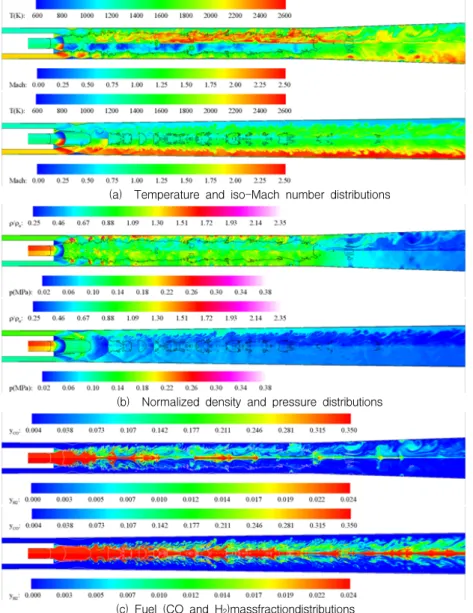
(a) Temperature and iso-Mach number distributions
(b) Normalized density and pressure distributions
(c) Fuel (CO and H2)massfractiondistributions
Fig. 3 Instantaneous flow structures in combustor 1 (upper) and combustor 2 (lower) overlaid with sonic line (M=1.0, black solid curves).
this study a simplified flow condition and two combustor configurations as seen in Table 1 and Fig. 2 is considered as a preliminary step of studying the flame stability and combustion dynamics in DCR. The combustor 1 is composed of coaxial fuel and air flow in a constant area duct followed by divergent section, while the combustor 2 has a divergence angle from the beginning of the
combustor. All other flow variables and computational conditions remain same during the entire computational time.
Figure 3 is the instantaneous flow field for the two combustors. The turbulent combustion characteristics in supersonic shear layer is clearly captured with fine structures of various levels of eddy motions before the constant area combustor section in combustor 1. Flame
- 374 -
lift-off is also captured well for this configuration. In the meanwhile, combustion is not fully accomplished in the combustor 2 due to the expansion effect caused by a small divergence angle in axi-symmetric configuration. Thus, combustion efficiency in combustor 1 seems to be quite high, but is much lower for the combustor 2, as noticed by fuel distribution. As a result, flow Mach number of the main air flow in the combustor 1 is around 1.0, while it is much higher in combustor 2.The turbulent boundary layer is considered as not being important for the turbulent flame structure, but could be important to account for the compressibility effect on the turbulent combustion. The DES approach capturing the wall boundary layer captured in RANS mode, as shown in Fig. 3 seems to be appropriate avoiding the higher grid resolutions required to resolve wall turbulence by LES. The multi-dimensional limiting process (O-MLP) scheme applied revealed the great contribution in capturing the turbulent eddy motions compared with one-dimensional higher order scheme, resulting higher combustion efficiency at the same conditions.
More detailed and quantitative analysis could be addressed in the final paper.
참 고 문 헌
1. Billig, F. S., Waltrup, P. J., Stockbridge, R.
D., "Integral-Rocket Dual-Combustion Ramjets: A New Propulsion Concept", J.
Spacecraft, Vol. 17, No 5, Sept. 1980, pp.
416-424.
2. Shin, J.-R., Moon, S.-H., Won, S.-H., and Choi, J.-Y., “Detached Eddy Simulation of Base Flow in Supersonic Mainstream,”
Journal of KSAS, Vol.37, No.10, Oct. 2009,
pp.955~966.3. Choi, J.-Y., Yang, V. and Ma., F.,
"Combustion Oscillations in a Scramjet Engine Combustor with Transverse Fuel Injection," Proceedings of the Combustion
Institute, Vol. 30/2, Jan. 2005, pp. 2851.
4. Kim, S. Kim, K.-H. and Lee, S., “Wave number-Extended High-Order Oscillation Control Finite Volume Schemes for Multi-dimensional Aeroacoustic Computations”, Journal of Computational