Superconductivity and Cryogenics
Vol.15, No.2, (2013), pp.44~47 http://dx.doi.org/10.9714/psac.2013.15.2.044
```
1. INTRODUCTION
The large power HTS applications require not only a large current capacity but also low AC loss characteristics of the HTS conductor as the major part of the systems.
However, the HTS wires, which usually form a shape of a thin tape, just start to be developed for large current capacity. Generally, a several number of HTS wires should be combined to be used because a single HTS wires is yet limited in current capacity so far. Although many researchers are being progressed like Roebel conductors, compact cables, and HTS cable in conduit conductors for large current, none of them has shown the brightness of the usefulness for large power applications [1, 2]. Some of them was too expensive or too complicated to make, and others couldn't show clear reduction of AC loss. In application stage with the large current conductors, the AC loss is very important theme because it is closely related with operation efficiency. To reduce the AC loss from a bundle of the HTS single wires, we need to focus on the reduction of the magnetization loss by external magnetic field, because the magnetic field applied perpendicularly on the wide face of the HTS wire is generally dominates the AC loss characteristics of it. Theoretically, the magnetization loss can be reduced by making fine superconducting filaments and decoupling between them by twisting them [3–5]. We have investigated the effect of the striation as a substitution of the filament in the concept of the HTS compact cable, which has been proposed by a research group of NIST and University of Colorado for large current conductor [6, 7]. We prepared some sample HTS compact conductors with
various striations on the superconducting layers, and measured their magnetization loss from the external magnetic field with various incident angles. Finally, a proper measurement scheme of AC loss for a compact cable made by striated HTS wires.
2. EXPERIMENTS 2.1. Experimental setups and measurement
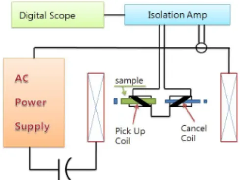
We fabricated linked pick-up coils (LPC) to measure the magnetization loss of the HTS conductor caused by the external magnetic field, which had been proposed by Z.
Jiang and N. Amemiya [8]. Fig. 1 shows a configuration of the AC loss measurement system. We also fabricated a racetrack AC magnet with uniformity within 1.0 % of magnetic field in the region of LPC and cancel coils to apply the uniform alternative magnetic field on the sample.
Fig. 1. Configuration of the experimental setup for measuring the magnetization loss.
Test result of striated HTS compact cables for low AC loss
Y. Kima, W. S. Kim*, a, and J. K. Lee b
a Korea Polytechnic University, Gyeonggi-do, Korea
b Woosuk University, Jeollabuk-do, Korea
(Received 11 June 2013; revised or reviewed 25 June 2013; accepted 26 June 2013)
Abstract
Large AC loss from the second generation (2G) high temperature superconducting (HTS) wires has been one of the major bottlenecks in power applications with HTS materials. Moreover, the large power applications also require the large current capacity from the HTS wires, which makes them produce larger AC losses. In order to reduce the AC loss from the HTS conductors with large current capacity, an HTS compact cable with some striations on the superconducting layers has been proposed. In this paper, we prepared some sample HTS compact conductors with striations, and measured their magnetization loss from the external magnetic field. We also made some slits on the superconducting layer of the HTS wire by laser cutting to reduce the aspect ratio of the superconducting layers. It would make the low eddy current loss and magnetic decoupling. Finally, the magnetization losses of the sample HTS compact conductors were measured and analyzed.
Keywords: AC loss, HTS, Compact conductor, Striation
* Corresponding author: [email protected]
Y. Kim, W. S. Kim, and J. K. Lee
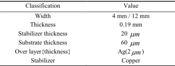
TABLE I
SPECIFICATIONS OF THE HTS WIRE.
Classification Value
Width 4 mm / 12 mm
Thickness 0.19 mm
Stabilizer thickness 20 µm
Substrate thickness 60 µm
Over layer{thickness} Ag(2µm)
Stabilizer Copper
The LPCs were wound by copper wire with diameter of 50 micrometer, and the number of turns was 600 turns each.
The fabricated LPCs were placed inside the racetrack coil with fixed to HTS samples to measure the AC loss.
The magnetization loss can be calculated by the voltage from the LPC and cancel coil, which are connected in anti-series, and the current from feeding line to the magnet expressed as (1),
∫ ⋅
= T
s pu
m vt it dt
V k
Q C 0 () () (1)
, where the VS is sample volume enclosed by the supporting box of LPCs and T is one cycle period of the AC signal. k is the magnet constant which is the magnetic flux density generated at the sample position per magnet current. Cpu is the pick-up coil calibration factor. To confirm of magnetization loss dependency of angle to external field, set 4 kinds of degrees. Set as 0, 30, 45 and 90 degrees, 90 degree means perpendicular to external field.
2.1. Samples
The HTS wire used for samples was supplied by SuNAM Corporation in Korea and its specifications are as listed in Table I. The configuration of the HTS compact cable which has helically wound several type of HTS wires around the insulated core with a constant pitch is as shown in Fig. 2. It has helically wound HTS wires around the insulated core with a constant pitch as shown in Fig. 2. We fabricated the samples with various pitches, such as 30 mm, 60 mm, and 120 mm considering the effective length of LPC, which is actually 60 mm. For the reduction of the AC loss, the superconducting layer of the wire has been separated into several filaments by laser striation. The striation should be carefully done to guarantee the electrical insulations between the filaments. The specifications of the HTS samples are shown in Table II.
Fig. 2. Configuration of the samples of the HTS compact cables with various pitches.
TABLEII
SPECIFICATIONS OF HTS SAMPLES. Specification of sample
4 mm thickness
sample
Sample length 120 mm
No. of striations 1 0(F1), 1(F2) 2(F3), (F4) Tilt angle for
external B 0, 30, 45, 90 -
Former diameter 10 mm
Helical period 1, 2
12 mm thickness
sample
Sample length 120 mm
No. of striations 0(F1), 4(F5), 9(F10) Tilt angle for
external B 90, 0
Former diameter 10 mm
Helical period 1, 2
3. RESULTS AND DISCUSSIONS
We measured the magnetization loss of each sample caused by the external magnetic field of 60 Hz frequency.
The magnetization loss of a straight single HTS wire by the external magnetic field with various incident angles was measured in order to verify the measurement system works properly or not. Fig. 3 shows the test results which shows that the measurement system was working properly.
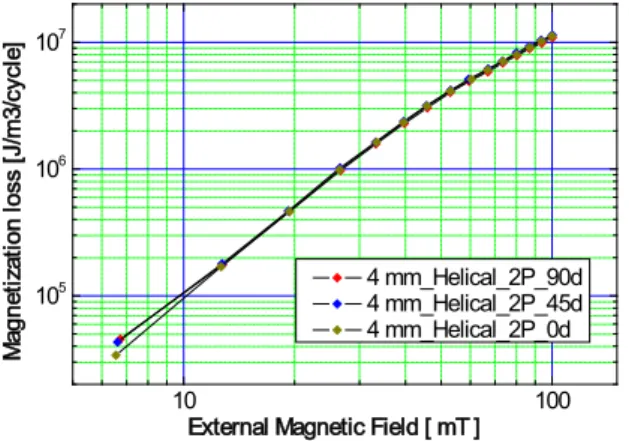
Using the measurement system, we measured the AC losses from the sample HTS compact cables listed in Table II with magnetic fields in different incident angles. The effective length of the LPC and cancel coil was 60 mm which was 0.5, 1.0, and 2.0 pitches of the samples. The test results are shown in Fig. 4, Fig. 5, and Fig. 6. The magnetization loss from the samples with pitches of 1.0 and 2.0 in the LPC didn’t show any dependency on the incident angles of the external magnetic field, which are shown in Fig. 5 and Fig. 6. However, the other sample shows angular dependency of the external magnetic field, which is shown in Fig. 4. Also, the AC losses of the compact cable samples
10 100
104 105 106 107
External Magnetic Field [ mT ] Magnetization loss [J/m3 /cycle]
4 mm_Straight_90d 4 mm_Straight_60d 4 mm_Straight_45d 4 mm_Straight_30d
Fig. 3. Angular magnetization losses of 4 mm straight samples.
1 F denotes the number of the filaments
45
Test result of striated HTS compact cables for low AC loss
10 100
105 106 107
External Magnetic Field [ mT ]
Magnetization loss [J/m3/cycle]
4 mm_Helical_0.5P_90d 4 mm_Helical_0.5P_45d 4 mm_Helical_0.5P_0d
Fig. 4. Angular magnetization losses of 0.5P, 4 mm helical samples.
10 100
105 106 107
External Magnetic Field [ mT ]
Magnetization loss [J/m3/cycle]
4 mm_Helical_1P_90d 4 mm_Helical_1P_45d 4 mm_Helical_1P_0d
Fig. 5. Angular magnetization losses of 1P, 4 mm helical samples.
10 100
105 106 107
External Magnetic Field [ mT ]
Magnetization loss [J/m3/cycle]
4 mm_Helical_2P_90d 4 mm_Helical_2P_45d 4 mm_Helical_2P_0d
Fig. 6. Angular magnetization losses of 2P, 4 mm helical samples.
were smaller than that of the straight one.
The results may be caused by the fact that the helically wound HTS wires on the compact cable does not totally expose their wide face to the external magnetic field.
Making filamentary superconducting layers with laser striation would help reducing effect of the AC losses. Fig. 7 and Fig. 8 show the results of the effect of the striations on AC losses, which show the expected results. They just show the striation effect but angle dependency. When the number
10 100
104 105 106 107
Magnetization loss [J/m3 /cycle]
External Magnetic Field [ mT ] 4 mm_Helical_1P_Per_1f 4 mm_Helical_1P_Per_2f 4 mm_Helical_1P_Per_3f 4 mm_Helical_1P_Per_4f
Fig. 7. Perpendicular magnetization losses of 1P, 4 mm helical samples.
10 100
104 105 106 107
External Magnetic Field [ mT ] Magnetization loss [J/m3 /cycle]
4 mm_Helical_1P_Par_1f 4 mm_Helical_1P_Par_2f 4 mm_Helical_1P_Par_3f 4 mm_Helical_1P_Par_4f
Fig. 8. Parallel magnetization losses of 1P, 4 mm helical samples.
10 100
105 106 107
External Magnetic Field [ mT ] Magnetization loss [J/m3 /cycle]
12 mm_Straight_1f 12 mm_Straight_5f 12 mm_Straight_10f
Fig. 9. Number of superconducting layer filament magnetization losses of 12 mm Straight samples.
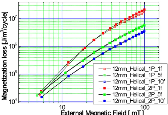
of the striations was increased to 10 filaments and the width of the HTS wire on the sample compact cable became 12 mm, it turned out that the measured AC loss of it showed much smaller than that of the samples with 4-mm width, which is shown in Fig. 9. As we can expect, the last sample didn’t show any angle and pitch dependency when the pitches were integer multiple of the effective length of the LPC and cancel coils.
46
Y. Kim, W. S. Kim, and J. K. Lee
10 100
104 105 106 107
Magnetization loss [J/m3 /cycle]
External Magnetic Field [ mT ] 12mm_Helical_1P_1f 12mm_Helical_1P_5f 12mm_Helical_1P_10f 12mm_Helical_2P_1f 12mm_Helical_2P_5f 12mm_Helical_2P_10f
Fig. 10. 12 mm width, helical samples of magnetization losses.
4. CONCLUSION
We prepared the samples of the HTS compact cable with different pitches and number of filaments to investigate the AC loss characteristics, especially the magnetization loss by the external magnetic field. The helically wound HTS wires showed expected reduction of the magnetization losses caused by the configuration of the HTS wires exposed to the external magnetic field. The striation on HTS tape is also effective to reduce the magnetization loss of the HTS compact cable as already proven for the straight HTS wire. Moreover, the HTS compact cable with striated HTS wires on it didn’t show any angle dependency either, which is very positive characteristics for the power applications requiring HTS windings. We would like to note that the importance of the size of LPC for a precise measurement of the magnetization loss of the compact cable. The effective length of the LPC and cancel coil should be the integer multiple of the winding pitches of the
helically wound HTS wires on the compact cable.
ACKNOWLEDGMENT
This research was supposed by Basic Science Research Program through the National Research Foundation of Korea(NRF) funded by the Ministry of Education, Science and Technology (2012R1A1A4A01012300).
REFERENCES
[1] M. Park, K. Choi, S. Hahn, G. Cha, and J. Lee, “Effect of the stack in HTS tapes exposed to external magnetic field,” IEEE Trans. Appl.
Supercond., vol. 14, no. 2, pp. 1106-1109, Jun. 2004.
[2] Z. Jiang, N. Amemiya, K. Kakimoto, Y. Iijima, T. Saitoh, K. Suzuki, and Y. Shiohara, “Total AC loss characteristics in a stacked YBCO conductor,” IEEE Trans. Appl. Supercond., vol. 17, no. 2, pp.
2442–2445, Jun. 2007.
[3] J. Ogawa, S. Fukui, M. Yamaguchi, T. Sato, and O. Tsukamoto,
“Magnetization loss in a striated YBCO coated conductor considering the intrinsic critical current distribution,” IEEE Trans.
Appl. Supercond., vol. 16, no. 2, pp. 111–114, Jun. 2006.
[4] J. K. Lee, W. S. Kim, C. Park, S. Byun, B. W. Han, S. Lee, S. Park, and K. Choi, “Estimation of magnetization loss at angular magnetic field using perpendicular magnetization loss in striated and transposed YBCO coated conductor,” Phys. C, Supercond., vol.
469, no. 15–20, pp. 1432–1435, May 2009.
[5] J. K. Lee, S. Byun, B.-Y. Han, W.-S. Kim, S. Park, S. Choi, C. Park, and K. Choi, “Reduction effect on magnetization loss in the stacked conductor with striated and transposed YBCC coated conductor,”
IEEE Trans. Appl. Supercond., vol. 19, no. 3, pp. 3340–3343, Jun.
2009.
[6] S. Schuller, “AC-loss measurement of a DyBCO-Roebel assembled coated conductor cable (RACC),” in Proc. 19th ISS, 2006.
[7] D. C. van der Laan, X. F. Lu, and L. F. Goodrich, “Compact GdBa2Cu3O7−δ coated conductor cables for electric power transmission and magnet application,” Supercond. Sci. Technol., vol. 24, no. 4, pp. 042001, Apr. 2011.
[8] Z. Jiang and N. Amemiya, “An experimental method for total AC loss measurement of high Tc superconductors,” Supercond Sci.
Technol., vol. 17, no. 3, pp. 371–379, Mar. 2004.
.
47