Thermal Energy Harvesting용 센서회로의 저전력 구동 방법
Low-Power Operation Method of Thermal-Energy Harvesting Sensor Circuit
남 현 경*, 코아반팜*, 트란바오손*, 응웬반티엔*, 민 경 식*★
Hyun Kyung Nam*, Pham Van Khoa*, Tran Bao Son*, Nguyen Van Tien*, Kyeong-Sik Min*★
Abstract
In this paper, we propose low-power operational methods for thermal-energy-harvesting sensor circuits. Here, the amount of harvested current has been measured as low as 8uA. However the DC power consumption of the sensor circuit is known to consume much larger than 8uA. Thus, We propose the hardware-based power gating and software-based active/sleep timing control schemes, respectively, for controlling the power consumption of sensor circuit.
In the hardware-based power gating scheme, if the ratio of Toff/Ton is larger than 22, the sensor can consume less than 8uA. For the software-based active/sleep control scheme, if the ratio of Tslp/Tact is larger than 3, we can suppress the current consumption below 8uA. The hardware-based and software-based schemes proposed in this paper would be helpful in various applications of energy-harvesting sensor circuits, where the power consumption is limited by an amount of harvested energy.
요 약
본 논문에서는 열전에너지 하베스팅에 의해 구동되는 센서 회로를 저전력으로 동작시킬 수 있는 방법을 제안하였다. 본 논 문에서 사용되는 열전소자를 이용하면 에너지 하베스팅 회로에서 8uA의 전류를 얻을 수 있다. 그러나 구동하려고 하는 센서 의 전류 소비는 이보다 훨씬 크기 때문에, 본 논문에서는 하드웨어 방법으로 power gating scheme을 이용한 저전력 구동과 소프트웨어적으로 active/sleep control scheme을 이용한 저전력 구동 방법을 센서 회로에 적용하여 센서 회로의 전류 소비 를 감소시킬 수 있음을 보였다. 먼저 하드웨어 power gating scheme을 사용할 때에는 파워 게이트의 Toff/Ton의 비를 22보 다 더 크게 하면, 센서 회로의 전류 소비가 8uA 이하로 줄어드는 것을 확인하였다. 또한 소프트웨어 기반의 active/sleep control scheme에 의한 저전력 구동에서는 Tslp/Tact의 비를 3 이상으로 설정해주면 전류 소비를 8uA 이하로 줄일 수 있음 을 확인하였다. 본 논문에서의 결과는 열전에너지 하베스팅에 의해서 구동되는 다양한 센서 회로 설계 및 구현에 도움이 될 것으로 생각된다.
Key words
:
thermoelectric generator, low-power sensor operation method, thermoelectric energy harvesting, power- gating circuit, active/sleep mode.* Dept. of Electronics Engineering, Kookmin University
★ Corresponding author
E-mail:[email protected] Tel:+82-2-910-4634
※ Acknowledgment
The work was financially supported by NRF-2015R1A5A7037615 and C0564566. The CAD tools were supported by IC Design Education Center(IDEXC), Daejeon, Korea.
Manuscript received Jun. 11, 2018; revised Jun. 25, 2018; accepted Jun. 25, 2018.
This is an Open-Access article distributed under the terms of the Creative Commons Attribution Non-Commercial License(http://creativecommons.org/licenses/by-nc/3.0) which permits unrestricted non-commercial use, distribution, and reproduction in any medium, provided the original work is properly cited.
ISSN:1226-7244 (Print)
ISSN:2288-243X (Online) j.inst.Korean.electr.electron.eng.Vol.22,No.3,842∼845,September 2018
논문번호 18-03-49 http://dx.doi.org/10.7471/ikeee.2018.22.3.842
321
(842)
322 j.inst.Korean.electr.electron.eng.Vol.22,No.3,842∼845,September 2018
Ⅰ. 서론
IoT 응용에서는 배터리에 의한 에너지 공급이 용 이하지 않는 경우가 많기 때문에, 에너지 하베스팅 에 의해서 에너지를 공급하는 기술이 필요하다[1].
에너지 하베스팅이 가능한 에너지 소스는 태양빛, 진동, 체온 등이 있는데, 인체 부착형 웨어러블 응 용을 위해서는 사람의 체온으로부터 에너지를 얻 는 방법이 제일 적합한 방법으로 생각된다[2]. 그러 나 일반적으로 열전소자(Thermoelectric generato r:TEG)의 에너지 밀도는 매우 낮으므로 열전에 너지 하베스팅 기술에서는 시스템의 저전력 동작 이 매우 중요하게 된다[3]. 본 연구에서는 열전에너 지 하베스팅에 의해서 구동되는 웨어러블 센서 시 스템의 저전력 기술에 대해서 연구를 하고 이의 응 용을 보이고 실제로 동작함을 보이려고 한다.
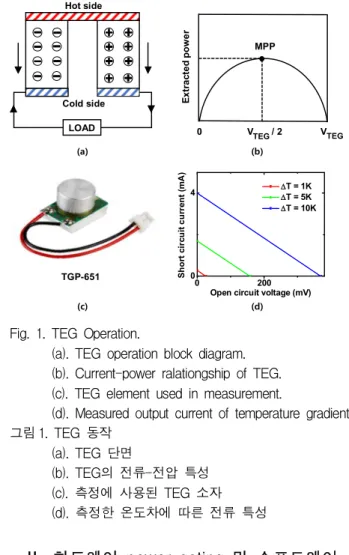
열전소자는 그림 1-(a)와 같이 hot side와 cold side 간의 온도 차에 따라 열에너지가 전기 에너지 로 전환되어 전류가 흐르는 소자이다. 열전소자의 전류-전압 특성이 그림 1-(b)에 나와 있다. 여기에서 open-circuit voltage와 short-circuit current의 1/2 지점 이 Maximum Power Point(MPP)라고 불리는 점이 며, 열전소자가 이 점에서 동작하도록 조건을 정해 줄 때, 열전소자는 제일 큰 전력을 생산할 수 있다 [4]. 그림 1-(c)는 본 논문에서 사용된 열전소자의 그림을 보여주고 있다. 모델명은 TGP-651이다. 그 림1-(d)는 그림 1-(c)에서 보여주고 있는 열전소자 의 실제 측정 결과를 나타내고 있다. 열전소자에 가해지는 온도의 차가 증가함에 따라 열전소자의 출력전압과 출력전류가 증가함을 확인할 수 있다.
본 논문에서는 열전소자 10개를 병렬 연결하여 에너지 하베스팅 회로를 시뮬레이션 하였다. 열전 소자 10개를 병렬로 연결할 경우에 전력변환회로 의 출력전압을 4.2V로 가정했을 때, 열전소자용 전 력회로는 대략 8uA 정도의 전류를 공급할 수 있음 을 알았다. 따라서 본 연구에서 사용하는 웨어러블 센서 시스템의 전력소비는 8uA 이하가 되어야 한 다. 이를 위해서 본 연구에서는 하드웨어 방법으로 power gating을 이용한 저전력 구동과 소프트웨어적으 로 active/sleep control할 수 있는 저전력 기법을 구 현하고 테스트하여 웨어러블 센서 시스템의 전력 소비를 열전소자 하베스팅에서 공급 가능한 범위로 맞출 수 있다는 것을 보이고자 한다. 하드웨어 scheme
에는 수동용 소자(LM35DT, 온도센서)를 사용하였으 며, 소프트웨어 scheme에는 I2C통신이 가능한 소 자(HDC1010,온습도센서)를 사용하였다[5-7].
LOAD Hot side
Cold side
(a) (b)
(c) (d)
VTEG V / 2TEG
MPP
Extracted power
0
TGP-651 00 200
4
Short circuit current (mA)
Open circuit voltage (mV) DT = 1K DT = 5K DT = 10K
Fig. 1. TEG Operation.
(a). TEG operation block diagram.
(b). Current-power ralationgship of TEG.
(c). TEG element used in measurement.
(d). Measured output current of temperature gradient.
그림 1. TEG 동작 (a). TEG 단면
(b). TEG의 전류-전압 특성 (c). 측정에 사용된 TEG 소자 (d). 측정한 온도차에 따른 전류 특성
Ⅱ. 하드웨어 power gating 및 소프트웨어 active/sleep control scheme
1. 하드웨어 power gating
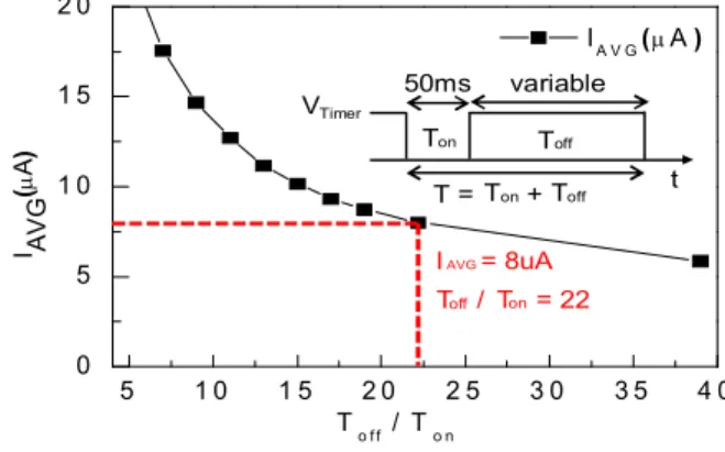
Power gating이 없는 하드웨어 센서회로의 평균 소비전류는 114.58uA이다. TEG를 이용한 하베스 팅 회로에서 공급할 수 있는 전류는 8uA로 센서회 로를 구동시키기에 충분하지 않기 때문에 평균소 비전류를 줄이기 위하여 하드웨어 power gating을 사용하였다[8]. Power gating을 위하여 Timer (TPL5110)를 사용하여 센서의 on/off time을 조절 하여 평균소비전류를 줄이는 방법을 사용하였다 [9]. Timer에 연결되는 저항을 변경하게 되면 전압 을 driving 해주는 주기가 달라지는데 이는 pulse width modulating(PWM)이라고 한다. 본 논문에서 사용된 timer는 low voltage time이 50ms이며, high
(843)
Low-Power Operation Method of Thermal-Energy Harvesting Sensor Circuit 323
voltage time은 주기에서 50ms를 뺀 값이다[10].
본 실험에서는 off time을 길게 할수록 평균소비전 류가 줄어들기 때문에 timer 뒷단에 switch 역할을 하는 PMOS를 연결하여 센서의 on time과 off time을 조절하였다. 이때 on time은 50ms로 고정 이 되게 하며, off time을 늘려서 전류 소비를 감소 시키게 하였다.
VDD
Timer (TPL5110)
Sensor
(LM35DT/Temperature)
on off
Ton
T = + 50ms
Timer
V
Toff
T T t variable
Fig. 2. Power gating using timer.
그림 2. Timer를 이용한 power gating
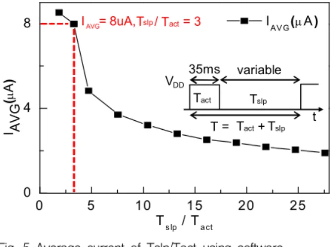
2. 소프트웨어 active/sleep control scheme Timing control을 갖는 온습도 센서의 DC 평균 소비전류는 32uA이다. 이 전류 또한 TEG를 이용 하여 얻는 하베스팅 전류로 구동시키기 부족하기 때문에 두 번째 방법으로는 소프트웨어를 이용한 active/sleep mode timing control을 진행하였다. 실 험에서 사용된 온습도 센서(HDC1010)는 I2C통신을 통하여 controller와 통신하게 되는데, 이를 이용하여 active/sleep mode 조절이 가능하다[8-9]. 본 실험에서 는 Arduino Flora를 controller로 사용하였으며, 데이터 를 요청하면 active, 요청한 데이터를 전달해주면 sleep mode로 변하는 센서의 특징을 이용하여 데 이터 요청주기를 변경하며 실험을 진행하였다.
T
T = + 35ms VDD
Tslp act
t Tslp
Tact
variable Sensor(HDC1010/
Humidity &
Temperature)
Controller (Arduino Flora) Active/sleep mode control
Instruction &
humidity/temperature
(SCL Line) (SDA Line)
Fig. 3 active/sleep control scheme using software.
그림 3. 소프트웨어 active/sleep control scheme
Ⅲ. 실험/측정 결과
1. 하드웨어 power gating
센서 회로의 DC 평균소비전류는 114.58uA이다.
하드웨어 power gating을 이용하여 센서의 Toff/
Ton의 비를 5로 하였을 때, 평균소비전류는 22.4uA, 7일 때 17.6uA로 줄어드는 것을 확인하였다. 평균 소비전류를 8uA 이하로 낮추기 위해선 Toff/Ton 의 비가 22 이상이 되어야 한다. 이때 추가되는 timer에 의한 오버헤드도 고려하여 Toff/Ton의 비 를 정하였다. Timer에서 소비되는 오버헤드 전류 는 3uA, 센서 회로에서 사용되는 평균소비전류는 5uA로 두 개를 합치면, 전체 소비전류가 8uA가 되 어서 에너지 하베스팅 회로의 공급 전류인 8uA와 같아지게 된다. 센서 회로의 전류소비는 그림 4와 같이 Toff/Ton의 비를 크게 할수록 소비전류가 줄 어드는 것을 확인할 수가 있다.
5 1 0 1 5 2 0 2 5 3 0 3 5 4 0 0
5 1 0 1 5 2 0
IA V G(mA )
I A(mA) VG
To f f / To n I = 8uA AVG
Ton
T = + 50ms
Timer
V
Toff on t T Toff
T /off T = 22on
variable
Fig. 4 Average current of Toff/Ton using hardware power gating.
그림 4. 하드웨어 power gating을 이용한 회로의 Toff/Ton 당 평균소비전류
2. 소프트웨어 active/sleep control scheme 소프트웨어 방법에서 사용된 센서 회로의 DC 평 균 소비전류는 32uA이다. Active/sleep mode control scheme에서 Tslp/Tact의 비를 3보다 크게 하면 소 비 전류를 8uA 이하로 할 수 있음을 확인할 수 있 었다.
본 실험에서 controller로 사용한 arduino flora는 많은 전류를 소비하기 때문에 저전력 센서 회로 구 동에 적합하지 않다. 이 arduino controller를 대신 하여 run time 시 88uA/MHz, standby mode일 때 0.27uA의 전류만을 소비하는 STM32L052x6을 사
(844)
324 j.inst.Korean.electr.electron.eng.Vol.22,No.3,842∼845,September 2018
용한다면 저전력 소비로 센서 회로를 구동시킬 수 있을 것이다.
0 5 10 15 20 25
0 4 8
I A(mA) VG
Ts lp / Tact
IAV G(mA) I = 8uA,AVG T / = 3slp Tact
T
T = + 35ms VDD
Tslp act
t Tslp
Tact
variable
Fig. 5 Average current of Tslp/Tact using software active/sleep control scheme.
그림 5. 소프트웨어 active/sleep control scheme을 이용한 회로의 Tslp/Tact 당 평균소비전류
Ⅳ. 결론
본 논문에서는 센서 회로를 저전력으로 구동시킬 수 있는 방법으로 하드웨어 power gating과 소프트웨 어 active/sleep control scheme을 제안하였다. 하 드웨어에서 사용된 센서 회로의 DC 평균소비전력은 114.58uA였고, 센서의 Toff/Ton time비를 22이상이 면 8uA이하의 평균소비전류를 얻을 수 있었다. 이 는 timer의 파워오버헤드를 포함한 수치이다. 소프 트웨어에서 사용한 센서 회로의 DC 평균소비전류 는 32uA이다. Tslp/Tact의 비를 3이상으로 해주면 8uA이하의 평균소비전류를 얻을 수 있다.
References
[1] Pouya Kamalinejad, Chinmaya Mahapatra, Zhengguo Sheng, Shahriar Mirabbasi, Victor C.M. Leung, and Yong Liang Guan, “Wireless energy harvesting for the Internet of Things,”
IEEE Communications Magazine, vol.53, no.6,
pp.102-108, 2015. DOI:10.1109/MCOM.2015.7120024 [2] Vladimir Leonov and Ruud J. M. Vullers,“Wearable electronics self-powered by using human body heat: The state of the art and the perspective,”
Journal of Renewable Sustainable Energy, vol.1,
no.6, 2009. DOI:10.1063/1.3255465
[3] Sravanthi Chalasani and James M. Conrad,
“A survey of energy harvesting sources for embedded systems,” IEEE SoutheastCon, pp.
442-447, 2008. DOI:10.1109/SECON.2008.4494336 [4] Loreto Mateu, Cosmin Codrea, Nestor Lucas, Markus Pollak, and Peter Spies, “Human Body Energy Harvesting Thermogenerator for Sensing Applications,” International Conference on Sensor
Technologies and Application, pp.366-372. 2007.
DOI:10.1109/SENSORCOMM.2007.4394949 [5] Texas Instruments, “Texas Instruments,”
http://www.ti.com/lit/ds/snis159h/snis159h.pdf.
[6] Frederic Leens, “An introduction to I2C and SPI protocols,” IEEE Instrumentation & Measurement
Magazine, vol.12, no.1, pp.8-13, Feb. 2009.
[7] Texas Instruments, “Texas Instruments,”
http://www.ti.com/lit/ds/symlink/hdc1010.pdf/.
[8] Hailin Jiang, Malgorzata Marek-Sadowska, and Sani R. Nassif, “Benefits and costs of power-gating technique,” International Conference
on Computer Design, pp.559-566. 2005.
DOI:10.1109/MIM.2009.4762946
[9] Texas Instruments, “Texas Instruments,”
http:// www.ti.com/lit/ds/symlink/tpl5110.pdf/.
[10] D. Grahame Holmes and Thomas A. Lipo,
Pulse width modulation for power converters:
principles and practice, John Wiley & Sons,
2003.(845)