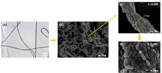
New Design of Li[Ni<sub>0.8</sub>Co<sub>0.15</sub>Al<sub>0.05</sub>]O<sub>2</sub> Nano-bush Structure as Cathode Material through Electrospinning
6
0
0
전체 글
(2)
(3)
(4)
(5)
(6)
수치
관련 문서
Among the sub-factors of autonomy support coaching behavior, strategy recognition had the most direct influence on the grit of athletes, followed by
For job characteristics sub-factors, while the average of functional diversity was high in graduate school graduates, the average of task importance, job
Second, as a result of the IPA analysis of the sub-factors of audience perception, the factors of entry route were located in the first quadrant, the
Among the five sub-content categories, only in the communication domain 'listening and speaking', the social relations domain 'living together' and the
This study was conducted to recognize the importance of self - management of dance major students and to understand the relationship between the sub -
For the gender, while training and direction, democratic direction, positive regard, and autocratic direction of leadership type sub-factors were perceived as high in
Fourth, for the sub-factors of personality traits according to weight lifters’ education, while there was a high difference in neuroticism and agreeableness
For the sub-factors of selection attributes and customer value according to screen golf course handicap, convenience, professionality, facilities, price,
