Ⅰ. 서 론
우리나라 통계청의 조사에 따르면 2000년 65세 이상 인구는 8.3%를 차지하였고 2020년에는 15.7%
를 거쳐 2040년에는 32%에 도달해서 급속히 고령화 사회로 들어설 전망이다.1이에 따라 총의치를 포함 한 의치를 필요로 하는 환자가 점점 증가할 것으로 예상된다. 그러나 전통적인 총의치는 소실된 자연치 아를 대체하기에 부족한 것으로서, 특히 하악 총의 치는 불편함과 통증을 유발하기 쉽고 잔존 치조골의 흡수도 심하여 저작 기능 회복에 있어서도 미흡하다 고 하겠다.2캐나다의 McGill Consensus에 의하면 기 존의 총의치를 이용한 하악 무치악 수복은 더 이상 보철치료에 있어서 첫 번째 선택이 아니며, 양측 이 공 사이에 2개의 임플랜트로 지지되는 피개의치가 하악 무치악 환자의 첫 번째 치료선택이 되어야 한 다고 하였다.3
Chiapasco 등4은 하악 이공 사이에 2개 임플랜트를 식립하고 즉시 부하를 가한 피개의치에서 3-8년 동 안의 성공률을 88.8%로 보고하였고, Menicucci 등5은 ball and socket attachment를 이용한 하악 임플랜트 지지형 피개의치가 clip and bar attachment를 이용 한 피개의치보다 작업측과 비작업측 무치악 점막으 로의 하중 분산이 우수함을 보고하였다. 또한 Trakas6도 독립된 ball attachment가 하악골의 휨을 허용하므로 응력의 분산에 있어서 연결시키는 형태
의 attachment보다 유리하다고 하였다. 반면 하악 임 플랜트 지지형 피개의치에서 clip and bar type attachment가 ball attachment보다 유지력에 있어서 더 우수하며7연조직의 건강과 환자 만족도에 있어서 두 종류 간 별 차이가 없다는 보고8도 있어왔다. 그럼 에도 불구하고 2개 임플랜트와 ball and socket attachment를 이용한 하악 피개의치는 하악 무치악 환자에게 유용한 보철치료 방법이라 여겨진다.
따라서, 본 연구의 목적은 상하악 완전 무치악 환 자에서 하악의 이공 사이에 2개의 임플랜트를 식립 하고, ball & socket attachment가 부착된 피개의치 를 장착 시킨 후, 임플랜트의 식립 위치에 따른 의치 의 동요도와 하악골 등에 미치는 응력분포를 3차원 유한요소 분석법을 이용해 비교 분석하는 것이다.
Ⅱ. 연구 재료 및 방법 1. 유한요소 분석을 위한 3차원 모델링
상하악 완전 무치악 환자에게 하악의 이공 사이에 2개의 임플랜트를 식립하는 치료 개념으로 모형을 제작하였다. 하악 무치악 모형을 제작하고 고무 인 상재를 이용하여 치은을 형성한 후 피개의치를 제작 하고(Fig. 1) 제작된 모형을 3D scanner(LC50, Metris HQ, Leuven Belgium)(Fig. 2)를 이용하여 유한요소 모델을 완성하였다(Fig. 3).
대한치과보철학회지:Vol. 45, No. 5, 2007
하악 임플랜트 유지형 피개의치의 안정성과 하악골 응력분포에 대한 3차원 유한요소법적 연구
경희대학교 치과대학 치과보철학교실, 경희대학교 구강생물학 연구소 홍해룡∙최대균∙백 진∙권긍록
※ 이 연구는 2006년도 경희대학교 연구지원에 의한 결과임. (KHU-20060348)
2. 모델 분류와 경계조건
scan된 3차원 모델을 이용하여 2개의 임플랜트가 식립된 조건이 서로 다른 4가지 모델을 제작하였다.
식립 임플랜트는 직경 3.8mm 길이 10mm인 Dentium일체형 Ball implant(Dentium Co. Ltd, Seoul, Korea)를 이용하였고, Retentive anchor로 Gold matrice(DALBO B, CEANDRES &
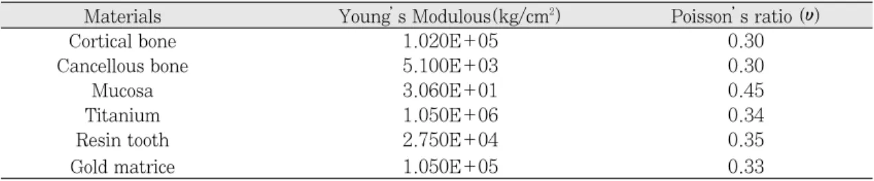
METAUX SA, Bienne, SWISS)를 부착한 모형을 가 정했다. 경계조건 중 고정점은 하악체 하연에 설정 하였고, 구성성분들의 물성치는 선현들의 연구 결과
9,10를 참조하여 적용하였다(Table I).
1) 모델의 분류
모델은 임플랜트의 식립위치와 각도에 따라서 4개 의 군으로 하였다. 가상의 교합 평면에 직각이 되면 서 서로 평행하게 식립한 군으로는 그 위치에 따라 서 양측 측절치 부위군(M1) 양측 견치 부위군(M2), 양측 제1소구치 부위군(M3)으로 구분하였으며, 식 립 각도에 따른 군으로 좌측 견치부에는 가상의 교 합 평면에 대하여 15도 원심으로 식립하고, 우측 견 치부는 15도 근심으로 경사시켜 식립한 군(M4)을 더하여 총 4개의 실험 군을 설계하였고, 대조군으로 는 임플랜트를 식립하지 않은 무치악 의치군(M5)으 로 하였다(Table II).
2) 적용 하중
적용 하중의 양식은 양측성 균형교합(Bilateral Balanced Occlusion : BL)과 편측성 군기능교합 (Unilateral Group Function : UL) 그리고 견치유 도 교합(Canine Protected Occlusion : CP)을 적용 하였다.11양측성 균형교합 하중의 적용은 하악 우측 을 작업측으로 설정하여 적용하중의 3/4을, 비작업 측으로 설정한 좌측에는 적용하중의 1/4을 각각의 해당 치아들에 나누어 작업측과 비작업측 동시에 가 하였고, 편측성 군기능교합 하중은 작업측 해당 치 아에, 견치유도 교합하중은 작업측 견치 절단연에 가하였다. 적용하중의 크기는 Lundeen 등12제시한 저작중의 bite force중 평균 closing force와 평균 opening force를 참고하였으며, 총의치 교합임을 고 려하여 이 수치의 1/5인 14N을 적용하였다. 교합양 식에 따른 하중 적용은 환자의 우측을 작업측으로 가정하여 해당하는 각각의 하악 치아 교합 접촉점에 하중을 동일하게 나누어 수평으로 적용하였다(Table III).
3) 변위량과 등가 응력의 산출
유한요소 해석 프로그램인 ANSYS (Ver. 8.0, Swanson Analysis System Inc, USA)를 이용하여 의치의 변위량과 하악골의 최대 등가응력(maximun EQV stress)을 관찰하였다. 변위량은 모델을 유한 Fig. 2. 3D scanner(LC50, Metris HQ, Leuven Belgium). Fig. 3. The FEA model divided into tri-
angular elements and nodes.
개의 요소로 mesh를 한 후 각 요소의 절점에 대하여 변위량을 x축, y축, z축 방향으로의 이동량을 계산하 였고 그 총합은 각 변위량 제곱의 합에 대한 제곱근 을 하여 구하였고 등가응력(Equivalent stress, von Mises stress)은 요소 내에 일어나는 응력의 총합으 로 계산하였고 응력은 각 모델을 하중조건에 따라 요소별로 등가응력과 최대 등가응력 구하였다.
Ⅲ. 결 과
1. 임플랜트 식립위치에 따른 의치의 변위량과 응력
견치유도 교합 하중양식은, 모든 실험조건에서 다 른 두 교합양식에 비해 매우 큰 변위량과 응력 분포 Table I. Material’s properties used in the FEA analysis
Materials Young’s Modulous(kg/cm2) Poisson’s ratio (υ)
Cortical bone 1.020E+05 0.30
Cancellous bone 5.100E+03 0.30
Mucosa 3.060E+01 0.45
Titanium 1.050E+06 0.34
Resin tooth 2.750E+04 0.35
Gold matrice 1.050E+05 0.33
Table II. Classification of models
Model Location of Implant fixtures Angle of inter-fixture
M 1 Lateral Incisors parallel
M 2 Canines parallel
M 3 1st. Premolars parallel
M 4 Canines 15�tilted toward
distally and mesially respectively M 5 conventional complete denture
Table III. Classification of load application
Type of occlusion Applied Force Applied area Loading point*
10.5N #43-47 (10.5N/5 each) working side
-Buccal slope of functional cusp BL
3.5N #37-33 (3.5N/5 each) non working side
-Lingual slope of functional cusp
UL 14N #43-47 (14N/5 each) working side
-Buccal slope of functional cusp
CP 14N #43 (14N) working side
-incisal edge
BL: Bilateral balanced occlusion. UL: Unilateral group functioned occlusion. CP: Canine Protected occlusion.
*Loading point is 2mm under the cusp tip along the cusp inclination.
를 나타냈다(Table IV). 이런 이유로 연구성적은 양측성 균형교합 하중양식과 편측성 군기능 교합 하 중 양식의 실험 결과만을 비교 분석하였다.
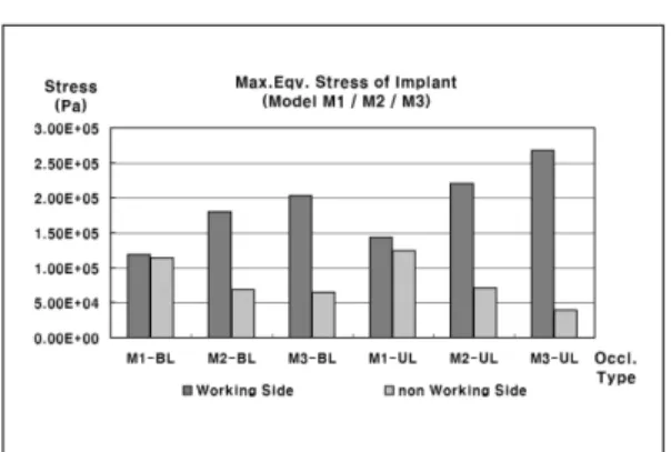
하악 임플랜트 지지형 피개의치 모델 M1, M2, M3의 변위량은 양측성 균형교합 하중(BL)과 편측성 군기능 교합 하중(UL)조건에서 비슷하게 나타났다 (Fig. 4). 두가지 하중 조건에서 하악골에 미치는 응 력은 모델 M1이 가장 작았으며(Fig. 5) 임플랜트에 미치는 응력은 작업측에선 모델 M1이 가장 작았고 비작업측에선 M1이 가장 컸다(Fig. 6). Female matrice에 미치는 응력 또한 작업측에선 모델 M1이 가장 작았고 비작업측에선 M1이 가장 컸다(Fig. 7).
2. 임플랜트 식립 각도 차이에 따른 변위량과 응력
견치위치 식립 임플랜트 지지형 하악 피개의치 모 델 M2와 동일 위치에 경사를 주어 임플랜트를 식립
한 모델 M4의 변위량은 각각의 하중 조건에서 모델 간 큰 차이는 없었다(Fig. 8).
하악골에 미치는 응력은 임플랜트를 경사 식립한 모델 M4에서의 하악골에 미치는 응력 값이 모델 M2에서의 값보다 작았다(Fig. 9). 임플랜트에 미치 는 응력은 작업측에선 모델 M4가 모델 M2보다 작 았고 비작업측에서는 반대로 모델 M4가 모델 M2보 다 컸다(Fig. 10).
Female의 matrice에 미치는 응력은 작업측에선 모 델 M4가 모델 M2보다 작았으며 비작업측에선 모델 M4가 모델 M2에 비하여 하중 조건에 따라 크거나 비슷했다(Fig. 11).
3. 임플랜트 지지형 피개의치와 전통적인 총의치 의 변위량과 응력 비교
모델 M1과 전통적인 무치악 총의치 모델 M5의 변 Table IV. Maximum Equivalent Stress(Pa) and Displacement of overdenture (m) Load Max.Eqv. Max. Eqv. Max. Eqv.Stress Max. Eqv. Stress Max. Eqv. Stress Overdenture’s Model Type Stress of Stress of working of non working of working side of non working total
mandible side Implant side Implant Female matrice side Female matrice displacement
BL 3.38E+04 1.19E+05 1.14E+05 1.39E+05 8.83E+04 2.47E-04
M1 UL 4.09E+04 1.44E+05 1.25E+05 1.73E+05 8.34E+04 3.24E-04
CP 2.77E+05 1.54E+06 1.29E+06 1.63E+06 9.39E+05 2.88E-03
BL 4.52E+04 1.80E+05 6.87E+04 1.70E+05 6.20E+04 2.48E-04
M2 UL 5.60E+04 2.20E+05 7.16E+04 2.22E+05 5.04E+04 3.25E-04
CP 2.84E+05 1.36E+06 7.30E+05 1.17E+06 5.98E+05 2.88E-03
BL 3.77E+04 2.03E+05 6.48E+04 1.76E+05 7.18E+04 2.46E-04
M3 UL 4.38E+04 2.68E+05 3.92E+04 2.30E+05 4.01E+04 3.23E-04
CP 2.75E+05 1.33E+06 4.24E+05 1.60E+06 5.10E+05 2.89E-03
BL 3.00E+04 1.63E+05 9.26E+04 1.02E+05 7.44E+04 2.47E-04
M4 UL 3.92E+04 1.93E+05 9.32E+04 1.16E+05 5.00E+04 3.24E-04
CP 2.52E+05 2.03E+06 8.89E+05 1.40E+06 5.98E+05 2.87E-03
BL 2.96E+04 2.47E-04
M5 UL 3.86E+04 3.24E-04
CP 1.28E+05 2.90E-03
M1: Model of Implant fixtures were in Lateral Incisor areas.
M2: Model of Implant fixtures were in Canine areas.
M3: Model of Implant fixtures were in 1st. Premolar areas.
M4: Model of Implant fixtures were in their angulation.
M5: conventional complete denture.
BL: Bilateral balanced occlusion. UL: Unilateral group functioned occlusion, CP: Canine Protected occlusion.
Fig. 4. Total displacement of model M1, M2 and M3.
M1: Model of Implant fixtures were installed in Lateral Incisor areas.
M2: Model of Implant fixtures were installed in Canine areas.
M3: Model of Implant fixtures were installed in 1st.
Premolar areas.
BL: Bilateral Balanced Occlusion.
UL: Unilateral Group Function.
Fig. 5. Maximum equivalent stress of mandibular bone.
M1: Model of Implant fixtures were installed in Lateral Incisor areas.
M2: Model of Implant fixtures were installed in Canine areas.
M3: Model of Implant fixtures were installed in 1st.
Premolar areas.
BL: Bilateral Balanced Occlusion.
UL: Unilateral Group Function.
Fig. 6. Maximum equivalent stress of working and non-working side implant.
M1: Model of Implant fixtures were installed in Lateral Incisor areas.
M2: Model of Implant fixtures were installed in Canine areas.
M3: Model of Implant fixtures were installed in 1st.
Premolar areas.
BL: Bilateral Balanced Occlusion.
UL: Unilateral Group Function.
Fig. 7. Maximum equivalent stress of working and non-working side female matrice.
M1: Model of Implant fixtures were installed in Lateral Incisor areas.
M2: Model of Implant fixtures were installed in Canine areas.
M3: Model of Implant fixtures were installed in 1st.
Premolar areas.
BL: Bilateral Balanced Occlusion.
UL: Unilateral Group Function.
Fig. 8. Total displacement of Model M2 and M4.
M1: Model of Implant fixtures were installed M2: Model of Implant fixtures were installed in
Canine areas.
M4: Model of Implant fixtures were installed in Canine areas with 30°medio-distal interim- plant angulation.
BL: Bilateral Balanced Occlusion.
UL: Unilateral Group Function.
Fig. 9. Maximum equivalent stress of Mandibular bone in Model M2 and M4.
M1: Model of Implant fixtures were installed M2: Model of Implant fixtures were installed in
Canine areas.
M4: Model of Implant fixtures were installed in Canine areas with 30°medio-distal interim- plant angulation.
BL: Bilateral Balanced Occlusion.
UL: Unilateral Group Function.
Fig. 10. Maximum equivalent stress of working and non-working side implant in Model M2 and M4.
M1: Model of Implant fixtures were installed M2: Model of Implant fixtures were installed in
Canine areas.
M4: Model of Implant fixtures were installed in Canine areas with 30°medio-distal interim- plant angulation.
BL: Bilateral Balanced Occlusion.
UL: Unilateral Group Function.
Fig. 11. Maximum equivalent stress of working and non-working side femal matrice in Model M2 and M4.
M1: Model of Implant fixtures were installed M2: Model of Implant fixtures were installed in
Canine areas.
M4: Model of Implant fixtures were installed in Canine areas with 30°medio-distal interim- plant angulation.
BL: Bilateral Balanced Occlusion.
UL: Unilateral Group Function.
위량은 각각의 하중 조건에서 비슷하게 나타났으며 (Fig. 12) 하악골에 미치는 응력은 모델 M1이 전통 적인 무치악 총의치 모델 M5보다 크게 나타났다 (Fig. 13).
Ⅳ. 고 찰
실제 임상에서, 발치 후 오랜 기간 흡수되어 위축 된 치조제에 임플랜트를 식립하는 치료 술식은 여러 가지 해부학적 요인으로 인해 제한을 받게 된다.
Chan 등13은 피개의치를 위한 임플랜트 식립 시 하악 에 비해 상악에서의 어려움을 언급하였고, Geertman 등14은 심하게 위축되고 흡수되더라도 하악 전치부에 선 임플랜트를 수용할만한 깊이와 높이의 치조제를 흔히 남기게 된다고 하였다. 본 실험에서는 이러한 임상 상황을 재현하고자 하악 전치부에 임플랜트를 식립한 모델을 설정하였고 교합 양식에 따른 영향을 보기 위해 교합면에 대한 수평하중을 각각의 하악치 아 교합접촉점에 하중을 동일하게 나누어 부여했으 며, 총 하중의 양은 상하악 총의치 교합상태임을 고 려해서 14N을 적용했다. 이는 Mu¨ller 등 선학들15의 연구에서 제시한 상하 총의치 환자의 최대 교합력 약 100N보다는 적은 힘을 적용한 것이었다.
∙임플랜트 식립위치에 따른 피개의치의 변위와 응력분포
Taylor16는 하악 임플랜트 지지형 피개의치의 2개 임플랜트 식립 위치의 선택에 대한 연구결과에서, 측절치 위치에 임플랜트를 식립하는 것이 견치 위치 보다 피개의치가 회전하는 움직임이 감소하고, 하악 전치의 기능시 절단연으로부터 임플랜트 간의 회전 축까지의 거리가 줄어들어 의치의 안정에 도움을 준 다고 하였다. 하지만, 본 연구에서는 임플랜트 식립 위치에 따른 피개의치의 변위량 차이가 나타나지 않 았다. 이것은 아마도 하중조건의 차이와 최대한 확 대된 의치상이 점막과 긴밀하게 접촉하고 있는 조건 을 부여한 실험모델을 사용한 결과로 여겨진다.
양측성 균형교합 및 군기능 교합의 하중 조건에서 하악골에 미치는 응력 결과는 측절치 임플랜트 식립 모델 (M1)에서 가장 낮은 것으로 나타나 잔존 하악 골의 보호 면에서도 유리할 것으로 추론된다. 식립 위치에 따른 모델 M1 M2 M3에서 임플랜트에 미치 는 응력과 female matrice에 미치는 작업측에서의 응 력을 비교 해보면 모델 M1이 다른 모델들에 비해 작 게 나타났고, 또한 각각의 모델 내에서 작업측과 비 작업측 응력 값을 비교해보면 그 응력 값들의 편차 도 모델 M1이 다른 모델들에 비해 작게 나타났는데 Fig. 12. Total displacement of Model M1 and M5.
M1: Model of Implant fixtures were installed in Lateral Incisor areas.
M5: Conventional complete denture.
BL: Bilateral Balanced Occlusion.
UL: Unilateral Group Function.
Fig. 13. Maximum equivalent stress of Mandibular bone in Model M1 and M5.
M1: Model of Implant fixtures were installed in Lateral Incisor areas.
M5: Conventional complete denture.
BL: Bilateral Balanced Occlusion.
UL: Unilateral Group Function.
이는 측절치 임플랜트 식립 모델 M1이 수평하중 시 에 작업측과 비작업측의 임플랜트 및 female matrice 로 응력이 잘 분산됨을 나타내는 것으로 생각된다.
하중적용 부위에서 식립된 임플랜트까지의 거리 관계를 살펴보면 하중적용 부위에 가까운 임플랜트 일수록 하중의 직접적인 영향으로 임플랜트에 미치 는 응력과 Female에 미치는 응력은 크게 나타났다.
모델 M1에서 모델 M4까지 식립된 8개 임플랜트의 위치를 고려해보면 하중적용 부위에서 멀어질수록 임플랜트에 미치는 응력은 작게 나타났다. 이는 Porter17등이 발표한 하악 임플랜트 지지형 피개의치 에서의 하중 분포에 관한 연구에서 하중을 식립된 임플랜트 가까이에 직접 가할 때에 가장 큰 force와 moment를 나타낸다는 결론과 유사하였다. 즉, 작업 측의 경우 하중작용 부위와 가까운 제1소구치 식립 모델(M3)은 가장 큰 임플랜트 응력과 Female응력을 나타내었고, 측절치 임플랜트 식립모델(M1)은 하중 적용 부위와 상대적으로 멀리 위치하므로 작은 응력 을 나타냈다.
Sadowsky와 Caputo18는 하악 임플랜트 지지형 피개의치에 대한 연구보고에서 이상적인 응력의 분 산을 위해서는 의치의 후방 연장의 긴밀한 접촉이 매우 중요하다고 서술한바 있다. 그러므로 임플랜트 지지형 하악 피개의치 경우에 의치 유리단이 길어지 고 점막접촉부의 면적이 넓어질수록 또한 하중 적용 점으로부터 피개의치 지지를 위한 임플랜트가 멀리 식립될수록 응력 분산에 유리하다고 예상할 수 있다.
∙임플랜트 식립 각도차이에 따른 변위와 위와 응 력분포 비교
견치 부위에 임플랜트를 평행하게 식립한 모델 (M2)과 경사 식립한 모델(M4) 간에 피개의치의 변 위량은 차이가 없었으나, 하악골에 미치는 응력은 모델 M4에서 낮게 나타났다. 특히, 임플랜트를 근심 으로 경사지게 식립한 작업측에서 임플랜트에 미치 는 응력과 female matrice에 미치는 응력이 작게 나타났다. Satoh 등19은 하악 구치부에 경사 식립한 임플랜트에 대한 3차원 유한요소 분석에서 자연치아 를 따라 근심설측으로 기울여 식립하는 것이 응력의 분산에 유리하다고 보고하였는데 비록, 구치부에 경
사 식립한 임플랜트의 결과이기는 하지만 본 실험의 결과와 유사한 것으로 생각된다.
모델 M4에서 원심 15도 경사 식립한 비작업측의 female matrice에 미치는 응력값이 수직으로 식립된 임플랜트의 female matrice에 미치는 응력값보다 크게 나타 났다. Gulizio 등20은 임플랜트 지지형 피개 의치에서 임플랜트 경사 식립이 유지력에 미치는 영 향에 대한 연구에서 임플랜트 경사도가 20도 이상일 때 통계적인 유의성을 보이며 그로 인해 Gold matrice의 헐거워짐이 심해진다고 보고하였다. 이 런 결과들을 토대로 볼 때, 하악 피개의치에 있어서 원심 경사 식립한 임플랜트의 경우에서 쉽게 Gold matrice가 헐거워지리라 예상된다.
∙임플랜트지지 피개의치와 전통적인 총의치의 변 위와 응력분포 비교
모든 하중 조건에서의 피개의치의 변위량은 측절 치 임플랜트 식립 모델(M1)과 전통적인 무치악 총 의치 모델(M5)에서 비슷한 값을 나타냈고, 하악골에 미치는 응력은 모델 M1에서 전통적인 무치악 총의 치 모델 M5보다 크게 나타났다.
본 실험의 결과는 임플랜트 지지형 피개의치가 전 통적인 총의치보다 의치의 변위와 응력 분산 측면에 서 우위에 있음을 보여주지 못했다. 이것은 유한요 소 분석을 위한 무치악골 및 의치 모델 작업 시, 실 제 임상 상황보다 더 긴밀한 적합을 가지는 이상적 인 의치로 설계된 점과 하중조건에 있어서 교합 양 식을 따라 적은 양의 수평하중만 적용한 하중조건에 의해 두 모델간의 변위량 차이를 보이지 않은 것으 로 생각된다. 또한 모델 M1이 M5에 비해 큰 응력값 을 보인 이유도 모델 M1은 측방력의 영향을 직접 받게되는 임플랜트가 식립된 모델이기 때문이며, 그 힘의 크기도 적정수준 이내인 것으로 생각된다.
그럼에도 불구하고, 2개의 임플랜트 지지형 피개 의치의 치조제 침하량은 전통적 총의치에 비해 적음 을 보고한 Kordatzis 등21의 하악 구치부 잔존 치조제 흡수에 대한 5년 간의 연구결과를 볼 때, 실제 임상 에서는 임플랜트에 의해서 응력분산 효과와 의치의 유지 및 안정성의 증대를 얻을 수 있다는 해석이 가 능하게 한다.
Meijer 등22과 Raghoebar 등23은 2개 임플랜트 지지
형 하악 피개의치를 이용하는 환자의 만족도가 전통 적인 총의치 환자에서보다 높다고 하였고, Visser 등24은 일반 총의치 장착자들의 안정과 유지의 저하 로 인한 불평과 그에 따른 저작능력의 감소를 보고 하면서 하악 임플랜트 지지형 피개의치에서 이러한 불만들이 확실히 줄어들었다고 보고한 바 있다. 이 와 같이 임플랜트지지 피개의치가 기존 의치의 문제 점인 구강 내에서의 안정성과 유지력을 개선시키고 환자의 만족도를 충족시킬 수 있는 치료술식임을 확 인할 수 있었다.
Ⅴ. 결 론
상하악 완전 무치악 환자에서 하악의 이공 사이에 2개의 임플랜트를 식립하고, ball & socket attach- ment가 부착된 피개의치의 3차원 유한요소 모델을 이용하여 임플랜트의 식립 위치와 교합 양식 하중에 따른 의치의 동요도와 하악골의 응력 등을 비교 분 석한 결과 다음과 같은 결론을 얻었다.
1. 견치유도 교합양식 하중은 하악 임플랜트 지지 형 피개의치에서 양측성 균형교합 및 군기능 교 합양식에 비해 임플랜트와 Female matrice에 미치는 응력이 가장 크게 나타났다.
2. 하악 양쪽 측절치 부위에 임플랜트를 식립한 피 개의치가 하악골과 주위 구조로의 응력분산에 가장 유리한 것으로 나타났다.
3. 하악 양쪽 견치 부위에 2개 임플랜트를 근원심 으로 경사 식립한 피개의치에서 근심경사 시킨 임플랜트는 정상 식립된 임플랜트보다 하악골 과 주위 구조로의 응력 분산에 유리하였다.
참고문헌
1. Korea National Statistical Office. 2006.
(http://www.stat.go.kr).
2. Wright PS. Two implants for all edentulous mandibles. Br Dent 2006;200:8:469.
3. Feine JS, Carlsson GE, Awad MA, Chehade A, Duncan WJ, Gizani S, et al. The McGill concensus statement on overden- tures. Mandibular two implant overdentures
as the first choice standard of care for ed- ntulous patients. Gerontology 2002;19:3- 4.
4. Chiapasco M, Gatti C. Implant-retained mandibular overdentures with immedi- ate loading: a 3- to 8-year prospective study on 328 implants. Clin Implant Dent Relat Res 2003;5:1:29-38.
5. Menicucci G, Lorenzetti M, Pera P, Preti G. Mandibular Implant-Retained Overde- nture: Finite element analysis of two an- chorage systems. Int J Oral Maxillofac Implants 1998;13:369-376.
6. Trakas T, Michalakis K, Kang K, Hirayama H. Attachment systems for implant retained overdentures: a literature review. Implant Dent 2006;15:1:24-34.
7. Petropoulos VC, Smith W, Kousvelari E.
Comparison of retention and release periods for implant overdenture attachments. Int J Oral Maxillofac Implants 1997;12:2:176- 85.
8. Karabuda C, Tosun T, Ermis E, Ozdemir T. Comparison of 2 retentive systems for implant-supported overdentures: soft tis- sue management and evaluation of patient satisfaction. J Periodontol 2002;73:9:1067- 70.
9. Borchers L, Reichart P. Three dimen- sional stress distribution around a dental implant at different stages of interface de- velopment. J Dent Res 1983;62:155-9.
10. Rieger MR, Fareed K, Adams WK, Tanquist RA. Bone stress distribution for three endosseous implant. J Prosthet Dent 1989;61:223-8.
11. Jo YH, Hobo S, Takayama H. Occlusion.
Koonja Publishing Inc. 1996;434-453.
12. Lundeen HC, Gibbs CH. Advances in cc- clusion. John Wright PSG Inc. Boston Bristol London. 1982;21-22.
13. Chan MF, Narhi TO, de Baat C, Kalk W.
Treatment of atrophic edentulous maxil- la with implant-supported overdentures:
a review of literature. Int J Prosthodont 1998;11:7-15.
14. Geertman ME, Boerrigter EM, Van Waas MA, van Oort RP. Clinical aspects of multicenter clinical trial of implant-retained mandibular overdentures in patients with severely resorbed mandibles. J Prosthet Dent 1996;75:194-204.
15. Mu¨ller F, Heath MR, Ott R. Maximum bite force after the replacement of complete den- tures. The Gerodontology Association 2001;18:58-62.
16. Taylor TD. Implant Overdentures: The Standard of Care for Edentulous Patients.
Quintessence Publishing Co, Inc.71-81.
17. Porter JA Jr, Petropoulos VC, Brunski JB.
Comparison of load distribution for implant overdenture attachments. Int J Oral Maxillofac Implants 2002;17:5:651-62.
18. Sadowsky SJ, Caputo AA. Effect of an- chorage system and base contact on load transfer with mandibular implant-re- tained overdenture. J Prosthet Dent 2000;84:327-34.
19. Satoh T, Maeda Y, Komiyama Y.
Biomechanical Rationale for Intentionally Inclined Implants in the Posterior Mandible
Using 3D Finite Element Analysis. Int J Oral Maxillofac Implants 2005;20:533-539.
20. Gulizio MP, Agar JR, Kelly JR, Taylor TD.
Effect of implant angulation upon reten- tion of overdenture attachments. J Prosthodont 2005;14:1:3-11.
21. Kordatzis K, Wright PS, Meijer HJ.
Posterior Mandibular Residual Ridge Resorption in Patients with Conventional Dentures and Implant Overdentures. Int J Oral Maxillofac Implants 2003;18:447- 452.
22. Meijer HJ, Raghoebar GM, van’t Hof MA, Geertman ME, van Oort RP. Implant- retained overdentures compared with complete dentures with or without pre- prosthetic surgery. A prospective study fol- lowed over 10 years. Ned Tijdschr Tandheelkd 2005;112:1:7-12.
23. Raghoebar GM, Meijer HJ, Stegenga B, van’t Hof MA, van Oort RP, Vissink A.
Effectiveness of three treatment modalities for the edentulous mandible. A five-year randomized clinical trial. Clin Oral Implants Res 2000;11:195-201.
24. Visser A, Meijer HJ, Raghoebar GM, Vissink A. Implant-retained mandibular overdentures versus conventional den- tures: 10 years of care and aftercare. Int J Prosthodont 2006;19:3:271-8.
Reprint request to:
Kung-Rock Kwon, D.M.D., M.S.D., Ph.D.
Department of Prosthodontics, School of Dentistry, Kyung-Hee University,
#1, Hoegi-Dong, Dongdaemun-Gu, Seoul, 130-701, Korea [email protected]
Statement of problem: Recently there are on an increasing trend of using implants - especially in edentulous mandible of severly alveolar bone recessed.
Purpose: The aim of this study was to analyze the displacement and stress distribu- tion of various mandibular implant-retained overdenture models supported by two implants in interforaminal region under the occlusion scheme load.
Material and method: FEA models were made by the 3D scanning of the edentulous mandibular dentiform. The three models were named as Model M1, M2, and M3 accord- ing to the position of implants: M1, Lt. incisor area, M2, Canine area, and M3, 1st Premolar area. Inter-implant angulation model was named as M4. Conventional complete denture was named M5 and used as a control group. Ball implant and Gold matrice were used as a reten- tive anchors. The occlusion type loads were applied horizontally over each tooth.
Results:
1. In mandibular implant retained overdenture Canine Protected Occlusion type load result- ed in higher levels of stress to the implants and female matrices than other types of loads.
2. The overdenture model, M1, with implants in lateral incisor areas resulted in lower stress concentration to the implants and female matrices than other models.
3. In mandibular implant retained overdenture the stresses of the implant and female matrice were lower in mesially inclined implant than these of parallel installed implant.
Conclusion: Lateral incisor areas could be the best site for the implants in mandibular implant-retained overdenture. The mandibular implant retained overdenture models mentioned above showed to the lowest stress to the implants and female matrices.
3D FINITE ELEMENT ANALYSIS OF OVERDENTURE STABILITY AND STRESS DISTRIBUTION ON MANDIBULAR
IMPLANT-RETAINED OVERDENTURE
Hae-Ryong Hong, D.M.D., Dae-Gyun Choi, D.M.D., D.D.Sc.
Jin Bak, D.M.D., M.S.D., Ph.D., Kung-Rock Kwon, D.M.D., M.S.D., Ph.D.
Department of Prosthodontics and Institue of Oral Biology, School of Dentistry, Kyung-Hee University
ABSTRACT
Key words : FEA, Mandible, Overdenture, Implant Angulation