Vol. 18, No. 3 pp. 681-686, 2017
Corrosion mitigation of photovoltaic ribbon using a sacrificial anode
Wonwook Oh, Sung-Il Chan
*1Electronic Convergence Material & Device Research Center, Korea Electronics Technology Institute
희생양극을 이용한 태양광 리본의 부식 저감
오원욱, 천성일*
전자부품연구원 융복합전자소재연구센터
Abstract Degradation is commonly observed in field-aged PV modules due to corrosion of the photovoltaic ribbon.
The reduced performance is caused by a loss of fill factor due to the high series resistance in the PV ribbon. This study aimed to mitigate the degradation by corrosion using five sacrificial anodes - Al, Zn and their alloys - to identify the most effective material to mitigate the corrosion of the PV ribbon. The corrosion behavior of the five sacrificial anode materials were examined by open circuit potential measurements, potentiodynamic polarization tests, and galvanic current density and potential measurements using a zero resistance ammeter. Immersion tests for 120 hours were also conducted using materials and damp heat test tests were performed for 1500 hours using 4 cell mini modules. The Al-3Mg and Al-3Zn-1Mg sacrificial anodes had a low corrosion rate and reduced drop in power, making then suitable for long-term use.
요 약 태양광 모듈에서 태양전지를 연결해주는 인터커넥터로 리본 솔더로 SnPbAg가 사용되고, 옥외 태양광 발전에 장기간 노출시 리본의 부식으로 인한 열화가 흔히 관찰된다. 이러한 부식현상으로 인하여 리본과 태양전지의 접합이 약해져 접촉저 항이 증가하고, 또한 리본 자체의 직렬 저항이 증가하게 되어 태양전지의 전압 전류 곡선에서 충진률 손실로 출력이 저하된 다. 본 논문에서는 리본의 부식을 완화시킬 수 있는 방법으로 희생양극법을 이용하여 순수 알루미늄 및 아연, 알루미늄, 아연 그리고 마그네슘의 합금을 이용한 5가지 희생양극 소재의 부식에 의한 열화 저감을 연구하였다. 전기화학적 방법으로 희생양 극 소재의 개방회로 전위와 폐쇄회로 전위를 측정하였고, 포텐시오다이나믹 분극 곡선을 측정하고, 영저항전류계를 이용하여 리본과 소재간의 갈바닉 전류를 측정하였다. 또한, 아세트산과, NaCl에 리본과 희생양극 소재의 부착 전후의 침지시험과 4셀 미니모듈로 제작한 후 1500시간 고온고습 시험 전후 출력을 평가하였다. 그 결과 Al-3Mg와 Al-3Zn-1Mg의 희생양극 소재가 부식속도가 느리고, 출력저하를 저감시킬 뿐만 아니라 장기 안정성에도 효과적인 것으로 평가된다.
Keywords : Damp heat test, Galvanic corrosion, Photovoltaic module, Photovoltaic ribbon, Sacrificial anode
This work was supported by the New & Renewable Energy of the Korea Institute of Energy Technology Evaluation and Planning (KETEP) grant funded by the Korea government Ministry of Trade, Industry and Energy.(No.20153010011980)
*Corresponding Author : Sung-Il Chan(Korea Electronics Technology Institute) Tel: +82-31-789-7054 email: [email protected]
Received November 21, 2016 Accepted March 10, 2017
Revised December 5, 2016 Published March 31, 2017
1. Introduction
Sn-Pb solder alloys have been widely used in industry because of their low melting points, low cost, good electrical conductivity, and good mechanical properties [1]. As an interconnector, photovoltaic (PV)
ribbon consists of solder-coated copper. It has high electric conductivity and low yield strength. The corrosion of an interconnector is classified as wear-out failure that can occur following long-term operation.
However, a decrease in the peak power (Pmax) was observed in PV modules that had been field-aged for
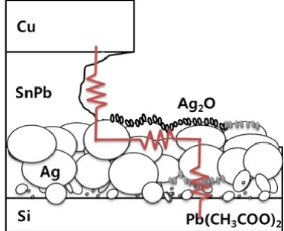
several years; this was because of the fill factor (FF) loss due to an increase in the series resistance (Rs) induced by the early degradation or failure of the interconnector [2]. The reported corrosion mechanisms (Fig. 1.) of the Ag electrode and SnPb solder are as follows:
(1) Following the reaction between Pb2+, as an additive in the silver paste, and CH3COO-, which is decomposed in the ethyl vinyl acetate (EVA), Pb(CH3COO)2 is formed at the top of the Ag finger and at the interlayer between the Ag and Si [3,4].
(2) A AgO2 layer is formed on the surface of the Ag finger, resulting in the line resistance of the Ag finger [5].
(3) The SnPb in the PV ribbon dissolves because of galvanic corrosion, which occurs because of the potential difference between the Ag and PV ribbon [6].
(4) The bulk Ag and crystallites at the edge of the Ag finger are oxidized by the thermal and humidity stress.
Additionally, the PV ribbon at the rear of the solar cell is vulnerable to moisture penetration through the backsheet. This degradation, due to corrosion, is a hindrance to long-term reliability.
The damp heat (DH)-induced degradation rate depends on the metallization process and quality of the Ag, water vapor content, and the production of acetic acid from the EVA. The deacetylation and hydrolysis of the vinyl-acetate monomers in the EVA results in the generation of acetic acid that could accelerate the corrosion of the electrical interconnectors [7]. The use of EVA with an acetic acid content greater than 2500 μg/g results in the degradation of the PV modules. A DH test over a period of 2000 h is sufficient to fill the EVA layer at the front of the solar cell with water vapor. The amount of acetic acid in an EVA layer of a PV module that has been field-aged for 20 years is relatively low compared to that which has been
subjected to a DH test for 2000 h [8].
The aim of this study is to identify the most effective sacrificial anode to mitigate the corrosion of a PV ribbon. We investigated the cathode protection of a PV ribbon with respect to galvanic corrosion, and conducted various electrochemical and DH tests on a mini module with various sacrificial anodes applied.
Fig. 1. Reported degradation mechanisms
2. Experimental
Pure Al and Zn, as well as Al-Mg, Al-Zn-Mg, and Zn-Al alloys were used as conventional sacrificial anodes, and the PV ribbon solder was composed of Sn36Pb2Ag (wt%). Table 1 shows the detailed chemical compositions for the five sacrificial anode samples. The corrosion behavior of the Al, Al alloys, Zn, and Zn alloys were investigated by open circuit potential (OCP) measurements, potentiodynamic polarization tests (closed circuit potential (CCP)), immersion tests, galvanic current density and potential measurements, and DH tests. All the electrochemical experiments were performed in a deaerated 0.1 M NaCl solution at room temperature, using a three-electrode system with a saturated calomel electrode (SCE) as the reference electrode, a Pt-plate as the counter electrode, and 1 cm2 samples as the working electrodes. The electrochemical tests were performed using a GAMRY
reference 600 potentiostat. The OCP, referred to as the corrosion potential, is the potential at which no current is recorded for 600 s. When the OCP stabilized following the immersion of the samples in a NaCl solution for 10 min, the potentiodynamic polarization curve measurements were conducted at a scan rate of 0.5 mV/s. The measurements of the galvanic current density and galvanic potential were conducted using the zero resistance ammetry (ZRA) technique in open circuit conditions [9]. The fluctuation in the current between the two identical working electrodes was recorded with respect to time, and the fluctuation in the potential between the working electrodes and the SCE was simultaneously recorded [10]. An increase in the current density and a decrease in Ecorr will be simultaneously observed when corrosion initiates on one of the working electrodes. Using this method, it is possible to quantify the induction time for passivity breakdown under an open circuit condition. A galvanic coupling immersion test was performed in 0.1 M NaCl for 120 h. The surface area of the sacrificial anodes was 0.6 cm2 and that of the SnPbAg was 3 cm2. The ratio of the surface area of the test anode to that of the cathode was 1:5. The anode and cathode were coupled together using conductive tape. Following the immersion test, the samples were ultrasonically cleaned using distilled water. We conducted a DH test (95
°C/95% RH, 1000 h) on the 2- and 4-point sacrificial anodes that were applied to the bus ribbon of a 4-cell mini-module; the size of each anode was 0.6 cm2.
3. Results and Discussion
Fig. 2 shows the OCP measurement results for the Sn36Pb2Ag, pure Al, Al-3Mg, Al-3Zn-1Mg, pure Zn, and Zn-0.5Al samples, following their immersion in a deaerated 0.1 M NaCl solution for 10 min. The Al-3Mg sample moved towards the positive potential during the initial stage of immersion because of the formation of an oxide film (MgO). Owing to the
formation of an Al2O3 layer, the Al sample also exhibited a higher potential than that of the standard hydrogen electrode (SHE) (1.66 VSHE). The Al-3Zn-1Mg affects the behavior of the passive Al, because it has a higher electronegative potential than pure Al. The corrosion potential of the pure Zn and Zn-0.5Al demonstrated similar results. Following the OCP measurements, potentiodynamic polarization tests were conducted by potential sweeping to obtain the CCP measurements.
Fig. 2. OCP and CCP of samples in 0.1 M NaCl
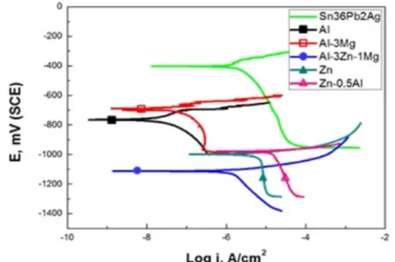
Fig. 3 presents the potentiodynamic polarization curves of the samples. The OCP and CCP results correlate well. From the OCP and CCP results, it can be determined that the pure Zn and Zn-0.5Al have similar corrosion potentials. However, the current density of the Zn-0.5Al alloy is greater than that of the pure Zn.
Fig. 3. Potentiodynamic polarization curves of samples in 0.1 M NaCl
The anodic and cathodic Tafel slopes, corrosion
potential (Ecorr), corrosion current density (Icorr), and corrosion rate of the samples were obtained from the potentiodynamic polarization curves; as shown in Table 2.
In terms of penetration, the corrosion rate can be calculated using Faraday’s Law. The Al-Zn-Mg sample has the lowest corrosion potential (OCP: -1134 VSCE, CCP:-1112 VSCE). The pure Al is unsuitable for use as a sacrificial anode for cathodic protection in seawater [11]. To increase the activity of the Al, a small amount of a metallic element such as Zn must be added [12]. The corrosion rate is expressed in terms of the weight loss, as mg per square decimeter per day (mdd) as shown in Eq. 1 [13].
Corrosion rate = (KW)/(ATD) (1)
Where:
K = constant (= 2.4×10⁶ D in mdd) W = mass loss (in g)
A = area (in cm2)
T = time of exposure (in h) D = density (in g/cm3))
The mdd values indicate the weight consumption and reflect the current density. The Zn and Zn-Al samples appear to have a higher corrosion rate than the other anodes. Where βa and βc are the anodic and cathodic Tafel slopes, respectively. The Al2O3 film is not stable in water and transforms into Al(OH)3 via hydration. The accumulation of the oxide and hydroxide films on the surface occurs slowly via Al dissolution and H2 evolution through the blocking of active sites. Because Zn is more electronegative than Al, it may preferably dissolve when subjected to anodic potentials. The samples have different potentials, thus resulting in anodic behavior for one and cathodic behavior for another. The galvanic current density and potential between the sacrificial anodes and the SnPbAg were measured by the ZRA technique.
Furthermore, these parameters were calculated from the Tafel curve.
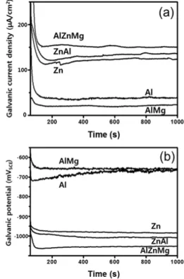
Fig. 4 shows the results for the galvanic current density, galvanic potential, and corrosion rate. The values calculated from the intersection of the potentiodynamic polarization curve were compared with those measured by the ZRA technique. The corrosion rate was calculated using Eq.1, using the results obtained from the ZRA measurements. For the sacrificial anode material to be suitable for long-term use, there should be a relatively large corrosion potential difference (low corrosion potential) between the SnPb solder and the sacrificial anodes.
Fig. 4. (a) Galvanic current density and (b) galvanic potential between sacrificial anodes and SnPbAg
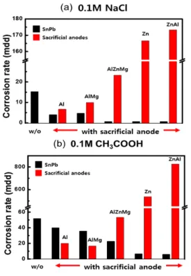
Fig. 5 shows the corrosion rates calculated using the mass loss that occurred following the immersion test.
The Zn and Zn-0.5Al anodes are unsuitable for long-term use because of their high corrosion rate. The Al-3Zn-1Mg anode appears to have a satisfactory corrosion rate and the consumption of SnPbAg is low with its use.
Fig. 5. Corrosion rates following the immersion test with galvanic coupling in 0.1 M NaCl(a) and 0.1 M CH3COOH(b) for 120 h (mdd = mg/100 cm2/day)
Fig. 6 indicates the results of the Pmax drop rate that were obtained from the DH test (95 °C/95% RH, 1000 h) performed on the 4-cell mini-modules. 2- and 4-point sacrificial anodes consisting of Al, Al-3Mg, and Al-3Zn-1Mg were applied at the ends of the PV ribbon. Compared to its initial value, the mini module without the sacrificial anode presented a Pmax drop rate of 4.5%. The samples with the sacrificial anodes showed a reduction in the Pmax drop rate.
Fig. 6. Pmax drop rate following the DH test
Fig. 7 and table 1 show the light I-V parameters following a period of 1500 h. The FF loss via the Rs increase was reduced for the samples with the sacrificial anodes.
Fig. 7. I-V parameters following DH testing for 1500 h
Table 1. I-V parameters of Fig. 7.
Samples Pmax(W) Isc(A) Voc(V) FF(%) Rs(mΩ)
W/O 16.1 8.80 2.62 69.8 52.2
Al 16.5 8.77 2.62 71.7 48.8
AlMg 16.6 8.80 2.61 72.4 46.7
AlZnMg 16.7 8.74 2.63 72.6 46.7
We demonstrated the electrochemical behavior between the SnPbAg solder and the sacrificial anodes.
Because we cannot precisely determine the environment of the electrolyte inside the PV module, electrochemical tests have to be performed in an acetic acid solution to achieve a more accurate simulation.
4. Conclusion
Using electrochemical and DH tests, we evaluated the use of five sacrificial anodes to mitigate the corrosion of a PV ribbon. The Al-3Zn-1Mg sacrificial anode showed the lowest corrosion potential value, as measured by OCP and CCP; it also had a high galvanic current density, as measured by the ZRA technique.
The immersion test showed that the Zn and Zn-0.5Al sacrificial anodes had corrosion rates of over 160 mdd when they were galvanically coupled with SnPbAg.
The Zn and Zn-0.5Al sacrificial anodes were considered to be unsuitable because of their high consumption. Following the DH tests, there was a reduction in the power drop with the use of the Al-3Mg and Al-3Zn-1Mg sacrificial anodes compared to the PV module with the non-sacrificial anode.
References
[1] L. C. Tsao, “Corrosion Resistance of Pb-Free and Novel Nano-Composite Solders in Electronic Packaging,”
Corrosion Resistance, Dr Shih (Ed.), 2012, ISBN:
978-953-51-0467-4, InTech.
DOI: https://doi.org/10.5772/33228
[2] E. D. Dunlop, and D. Halton, “The Performance of Crystalline Silicon Photovoltaic Solar Modules after 22 Years of Continuous Outdoor Exposure,” Progress in Photovoltaics: Research and Applications, 2006.
DOI: https://doi.org/10.1002/pip.627
[3] C. Peike, S. Hoffmann, P. Hülsmann, B. Thaidigsmann, K.A. Weiβ, M. Koehl, and P. Bentz, “Origin of damp-heat induced cell degradation,” Solar Energy Materials & Solar Cells, 2013.
DOI: https://doi.org/10.1016/j.solmat.2013.03.022 [4] M. D. Kempe, G. J. Jorgensen, K. M. Terwilliger, T. J.
McMahon, C. E. Kennedy, T. T. Borek, “Acetic acid production and glass transition concerns with ethylene-vinyl acetate used in photovoltaic devices,”
Solar Energy Materials and Solar Cells, 2007.
DOI: https://doi.org/10.1016/j.solmat.2006.10.009 [5] T. H. Kim, N.C. Park, and D.H. Kim, “The effect of
moisture on the degradation mechanism of multi-crystalline silicon photovoltaic module,”
Microelectronics Reliability, 2013.
DOI: https://doi.org/10.1016/j.microrel.2013.07.047 [6] N. C. Park, “A Study on the Reliability of Crystalline
Silicon Photovoltaic Module Under Different Temperature and Humidity Conditions,” Ph. D. thesis, Korea University, 2013.
[7] T. Shioda, PV Module Reliability Workshop, 2012 [8] T. Shioda, “Acetic acid production rate in EVA
encapsulant and its influence on performance of PV modules,” 2nd Atlas/NIST PV Materials Durability Workshop, 2013.
[9] R. Sanchez-Tovar, M.T. Montanes, and J. Garcia-Anton,
“Thermogalvanic corrosion and galvanic effects of copper and AISI 316L stainless steel pairs in heavy LiBr brines under hydrodynamic conditions,” Corrosion Science, vol. 60, pp.118–128, 2012.
DOI: https://doi.org/10.1016/j.corsci.2012.04.001 [10] M. Z. Yang, J.L. Luo, Q. Yang, L. J. Qiao, Z. Q. Qin,
and P. R. Norton, “Effects of hydrogen on semiconductivity of passive films and corrosion behavior of 310 stainless steel,” Journal of the Electrochemical Society, vol. 146, pp. 2107–2112, 1999.
DOI: https://doi.org/10.1149/1.1391899
[11] B. M. Ponchel, R. L. Horst, “Aluminium performance of Al–Zn–Sn,” Materials Protection, vol. 7, 1968.
[12] S. Khireche, D. Boughrara, A. Kadri, L. Hamadou, and N. Benbrahim, “Corrosion mechanism of Al, Al–Zn and Al–Zn–Sn alloys in 3 wt.% NaCl solution,” Corrosion Science, vol. 87, 2014.
[13] J. R. Davis, Corrosion: Understanding the Basics.
Materials Park, Ohio: ASM International, 2000.
[14] T. Kaewmaneekul, and G. Lothongkum, “Effect of aluminum on the passivation of zinc–aluminum alloys in artificial seawater,” Corrosion Science, vol. 66, 2013.
Wonwook Oh [Regular member]
•Feb. 2011 : Ggachon Univ.
Information technology, MS
•Feb. 2015 : Korea Univ., Material science and engineering, PhD
•Feb. 2015 ~ current : Korea electronics technology institute, Researcher
<Research Interests>
PV modules and system
Sung-Il Chan [Regular member]
•Aug. 2001 : Suwon Univ., Industrial engineering, MS
•Feb. 2011 : Ajou Univ., Industrial engineering, PhD
•Feb. 1997 ~ current : Korea electronics technology institute, Principal researcher
<Research Interests>
PV modules and system, Industrial engineering