Vol.33, No.9 pp. 603~608, 2009 (ISSN-1598-5725)
Ship Manoeuvring Performance Experiments Using a Free Running Model Ship
Namkyun Im†, Jeong-Ho Seo*
†Faculty of Maritime Transportation, Mokpo Nat'l Maritime Univ.
* Faculty of Maritime Transportation, Mokpo Nat'l Maritime Univ.
Abstract : In this paper, a 3m-class free running model ship will be introduced with its manoeuvring performance experiments. The results of turning circle test and zig-zag test will be explained. The developed system are equipped with GPS, main control computer, wireless LAN, IMU (Inertial Measurement Unit), self-propulsion propeller and driving rudder. Its motion can be controlled by RC (Radio Control) and wireless LAN from land based center. Automatic navigation is also available by pre-programmed algorithm. The trajectory of navigation can be acquired by GPS and it provides us with important data for ship’s motion control experiments. The results of manoeuvring performance experiment have shown that the developed free running model ship can be used to verify the test of turning circle and zig-zag. For next step, other experimental researches such as ship collision avoidance system and automatic berthing can be considered in the future.
Key words : Free Running Model Ship, turning test, zig-zag test, GPS
†Corresponding author : [email protected] 061) 240-7213
* [email protected]
1. Introduction
Recently many researches on ship automatic navigation system have been carried out(Im, 2007). The one of systems required for these researches is a free running model ship. A free running model ship has been used in ship model basin area to validate or confirm ship’s manoeuvring/motion or resistance performance before the ship’s building(Shin, Yoon, 2008;2004). When a free running model ship is used in a basin, usually it is known that there are limits of basin size to fully test the ship’s performance. Therefore many researches have been carried out outdoor such as pond or river.
When experiment is conducted outdoor using a free running model ship, a lot of equipments are required such as IMU (Inertial Measurement Unit), GPS (Global Position System) and other facilities to get other ship’s information.
This paper will introduce MMU (Mokpo National Maritime university) free running model ship which can be used for ship’s manoeuvring/motion performance tests. The system is equipped with GPS and AIS to get ship’s real time position and other ship’s information. Main purpose of this model ship is to carry out ship’s intelligent navigation test where the ship navigate recommend sea route or ship avoid other ship in the sea without human control automatically. The research in this paper was carried out as the first step of these researches. The structural and functional concept of the free
running model will be introduced. AIS(Automatic Identification System) decorder program was also developed to obtain others ships' data. We carried out basic ship’s performance tests such as tuning circle and zig-zag test as a first step of ship intelligent navigation tests. We found good performance in the model ship and that the model can be utilized in ship intelligent navigation tests in the future.
2. The Structure of free running model ship
The explations of MMU free running model ship consists of following equipments and contents.
- Main electric system - Device control system - Signal measurement hardware - Data Transition Type - Model ship
2.1 Main electric system
A free running model ship usually requires high capacity
of power because it is operated open waters with wind, wave
or current disturbances. The electric system of MMU model
supplies its electricity to servo motors and computer power
and communication system. Two servo motors are equipped
in the model ship, one (700W) for propeller and the other
(100W) for rudder operation. In operation situations, the
servo motors always controlled, so capacity of battery is
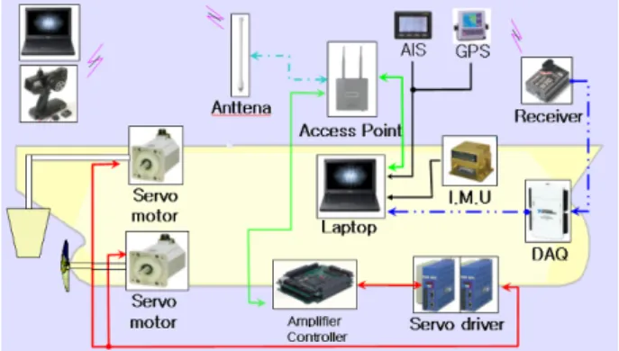
important to keep the model powered for long time. Two of battery are installed with a 12V deep cycle method and 100ah class of parallel circuits. Output power from batteries is sent to a DC/AC inverter and converted into 220V single-phase current for each electricity equipments. A current transformers or SMPS (Switching Mode Power Supply) of 24V or 12V often is used for small capacities equipments. The Fig. 1 explains the model ship' system flow.
Fig. 1 System flow in a model ship
2.2 Device control system
Control device system consists of access point (IEEE.802 11g), laptop computer, PMAC, servo driver and wireless control system. The following explains more details
- Laptop computer
It controls the total system of model ship. Its signal translated into each equipment with TCP/IP signal through a network adopter
- PMAC
When it receives TCP/IP singal, the output of range 0-10V is produced and sent to each servo driver such as rudder and propeller gears.
- Serve driver
It controls the rudder and propeller motors with siganls from PMAC.
- Radio control Receiver
The receiver get signals from radio control transmitter to control rudder angle and propeller revolution. The translated signal is sent to laptop computer by way of NI USB-DAQ.
2.3 Data acquisition hardware
The signals in a free running model can be into two types roughly. The first is signal for a ship motion control part and the second is for motion measurements such as 6 DOF (Degree Of Freedom). All signals from ship’s motion and control part is translated into laptop computer in the model
where each signal are stored or re-translated according to their purpose. The Fig. 2 explains the data acquisition system. The following explain measured signal at each equipment.
Fig. 2 Data acquisition system
- PMAC
Each phase generated in encoders of servo motor is input into PMAC via servo driver. The input phases are converted into meaningful data for rudder location and propeller revolution. The data also translated into laptop computer via TCP/IP to be stored as data log or monitoring purpose.
- NI-USB-DAQ
The data translated into radio control receiver is converted to PWM (pulse Width Modulation) signal. The NI-USB-DAQ translate the signal of PWM into laptop computer in model ship via USB port.
- 6 Axis IMU (Inertial Measurement Unit)
The signal data from IMU are translated into computer by serial communication. They are used for ship’s motion logging and monitoring.
- GPS (Global Position System)
The signal data from GPS also are translated into computer by serial communication. They are used for logging and monitoring of ship’s trajectory.
- AIS (Automatic Identification System)
It is equipped to obtain other ship’s information such as ship’s position, heading angle and speed. Its signal also translated as serial data into computer. This system can be used as one of intelligent navigation system. When a model ship avoids collision situations, the data from AIS is very essential to calculate the risk of collision between two ships.
2.4 Data transition type
A communication system of the model ship can be divided
into three types of analogue signal, TCP/IP and RS-232. The following are explanations of equipments and protocol.
- Digital and analogue signal
Encoders in servo motor produce several pulse. Control signal for servo motor ranges from 0V to 10V. The NI-USB-DAQ adopted in the model ship has spare channel for singal I/O , therefore additional hardware installation will be convenient such as wind and current meters and additional propulsion equipment.
- TCP/IP
The access point(IEEE. 802.11g), a close range wireless communication protocol, enable users to transmit data with 54Mbps. The communication between the laptop computer in the model ship and shore control center is possible by TCP/IP. The signal to/from PMAC is translated via access point with form of TCP/IP to control ship’s operation.
- RS 232
Several equipments such as IMU, AIS and GPS use serial data transmission, RS 232. All data from these equipments are stored in laptop computer system for logging and monitoring of the ship’s situations.
- PWM (Pulse Width Modulation)
Emergency situations such as model ship power failure or collisions require prompt and direct control. Radio control transmitter- receiver deals their signal with PWM method.
When NI-USB-DAQ receives pulse from radio control receiver and decides what kinds of control should be done using the pulse’s time from raising edge to falling edge.
2.5 Model ship
The model ship has 1/100 of model scale(SIMMAN, 2008).
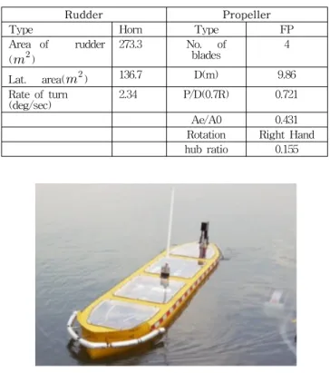
Water-proof was considered in every hatch to prevent capsizing of the model. The table 1 and 2 show the principal of model ship. The Fig. 3 explains the model ship.
Table 1 Principal particulars of model ship
Ship Model
Scale ratio 1 1/100
Type Tanker Ship Tanker Ship
Design speed(m/s) 7.973 0.7973
L.B.P(m) 320 3.2
L.W.L(m) 325.5 3.255
B(m) 58.0 0.58
Depth(m) 30.0 0.3
Draft(m) 20.8 0.2080
WSA( ) 27320.0 2.7320
Volume( ) 312737.5 0.3127
Cb 0.8101 0.8101
Fn 0.142 0.142
Table 2 Principal particulars of model ship
Rudder Propeller
Type Horn Type FP
Area of rudder ( )
273.3 No. of
blades 4
Lat. area( ) 136.7 D(m) 9.86
Rate of turn
(deg/sec) 2.34 P/D(0.7R) 0.721
Ae/A0 0.431
Rotation Right Hand hub ratio 0.155
Fig. 3 Model ship
2.6 Other algorithm for model ship
The model ship can be equipped with AIS to receive other ship's information. The Fig. 4 shows the snap-shot of AIS decorder program. As shown in this figure, useful information such as navigation status, position, speed, turn of rate etc. are available through this program. These information can be used when the model ship is applied for intelligent control ship; when the model avoids dangerous ships automatically in next research step. The AIS decorder program is one of the important items that are essential for intelligent and automatic ship navigation system.
Fig. 4 AIS decorder program
3. The model operation
The operating system for the model ship can be divided into two system of software operating system and hardware operating system.
3.1 Operating system of software
Table 3 indicates software operating system adopted for the model ship. As shown this table, Window XP and LabView are used for OS and computer program language.
Table 3 Operating system of software
Computer OS Widows XP
Computer Language LabVIEW 8.5
device driver PMAC
NI-DAQ
3.2 Operating system of hardware
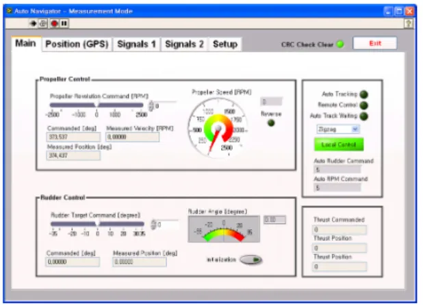
Critical control is done by inner computer on board which is controlled from shore computer with wireless network communication. A priority of control is set to radio control receiver-transmitter in specified frequency to cope with emergency situations. This enables users to take appropriate and prompt actions. In case of radio control receiver failure or networks signal errors, the inner computer of model ship is designed to run programmed sequence or process. The Fig. 5 indicates the priority of operation system. When local control mode is selected, model ship can be controlled by shore or inner laptop computer by manual mode. If local control mode is cancelled, radio control is searched at first.
When radio control signal is not found, automatic navigation control mode is activated.
Fig. 5 Main screen of operating program
Users can use additional safety measurement, the function of “fail safe” where radio control system can be kept specified conditions or stopped if radio transmitter-receiver
failed to get signals or the level of power in battery is so low. This enables the user to cope with emergency situations such as power failure in model ship or critical collision situation.
All data of model ship can be obtained from USB ports.
Additional equipment’s installation also is possible through spare ports of USB.
4. Experiments
In this research, two kinds of experiments are carried out in the costal sea and in a towing tank. Zig-zag test and turning test were performed. These tests are known as very essential and important method to evaluate a ship’s manoeuvring performances.
4.1 Zig-zag tests
Zig-zag test of 10˚/10˚ and 20˚/20˚ were performed with the range of 0.8-0.9kts speed. The experiments were carried out with almost no wind conditions and very calm sea conditions. The Fig. 6 shows the results of 10˚/10˚ zig-zag test carried out. The Fig. 7 shows the results of 20˚/20˚
zig-zag test carried out in the costal sea side. As shown in these figures, it is found that the model ship well perform zig-zag test without any errors and the data of ship’s heading and rudder angle also are very clear.
Fig. 6 10˚/10˚ zig-zag test
20' ZIG-ZAG
-35 -30 -25 -20 -15 -10 -5 0 5 10 15 20 25 30 35
0 5 10 15 20 25 30 35 40
Time(sec)
Angle(deg) Heading Rudder Roll
Fig. 7 20˚/20˚ zig-zag test in the sea
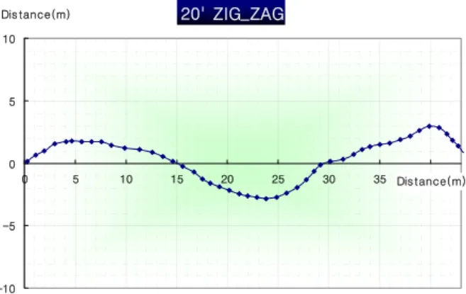
The Fig. 8 shows the ship’s trajectories obtained by GPS during ship’s zig-zag test.
20' ZIG_ZAG
-10 -5 0 5 10
0 5 10 15 20 25 30 35 Dis tance(m)40
Dis tance(m)
Fig. 8 Ship’s trajectories in 20˚/20˚ zig-zag test
Table 4 shows the comparison between model ship and IMO standard regulations of Ship's Manoeuvabiliy (IMO,2002). It is found that the result of model ship's zig-zag tests satisfy IMO rules.
Table 4 Comparison of Zig-zag tests
Test Type Model
[deg] IMO [deg]
10˚/10˚ deg Zig-Zag Test
1st OSA 7 20
2nd OSA 17.5 40
20 ˚/ 20 ˚
Zig-Zag Test 1st OSA 11 25
4.2 Turning circle test
Ship’s turning test also was carried out. A turning circle tests usually to be performed to both starboard and port with 35 degree rudder angle. The rudder angle is executed following a steady approach with zero yaw rate. The Fig.
9,10 and 11 show the results of turning test. As shown in these figure, the trajectories of the model and ship’s heading and rudder angle are clearly obtained to evaluate ship’s manoeuvring performances. The diameter of tactical is found around 7-8 meters. This experiment was performed in open sea.
Turning Circle
0 5 10 15
0 5 10 15 20 25 Distance(m)30
Distance(m)
Fig. 9 Ship’s trajectories in turning test
Turnig Circle
-40 -35 -30 -25 -20 -15 -10 -5 0 5
0 10 20 30 40 50 60 70 80 90
Time(sec) Angle(deg)
-270 -180 -90 0 90 180 270
Rudder Heading Angle Angle(deg)