MEMS Gyro North Finding 방법을 이용한 실내 이동로봇의 전방향 탐지
Indoor Mobile Robot Heading Detection Using MEMS Gyro North Finding Approach
위 원 룡1, 이 민 철†, 김 지 언2
Wei Yuan-Long1, LeeMin-Cheol†, KimChi-Yen2
Abstract This paper presents a new approach for mobile robot heading detection using MEMS Gyro north finding method in the indoor environment. Based on this, the robot heading angle measurement scheme is proposed; improved north finding theory and algorithm are also explained. Several approaches are applied to confirm system’s precision and effectiveness. In order to find out the heading angle, a single axis MEMS gyroscope to sense the angle between the robot heading direction and the north is used. To reach enough estimation accuracy and reduce detection time,the least square method (LSM) for the signal fitting and parameter estimation is applied. Through a turn‐table, we setup a carouseling system to decrease the substantial bias effect on gyroscope’s heading angle. For the evaluation of the proposed method, this system is implemented to the Pioneer robot platform. The performance and heading error are analyzed after the test. From the simulation and experimental results, system’s accuracy, usefulness and adaptability are shown.
Keywords: Mobile Robot, Heading Angle, North Finding, MEMS Gyro, LSM, Indoor Navigation
1. Introduction1)
Microelectrics mechanics system (MEMS) gyroscope has the characteristics of smaller size, lighter weight, and lower price than the traditional rate sensors and other navigation units. As the MEMS technique’s swift growth, the precision and stability have already got evidently improvement in the last three years. Auto- nomous navigation is an important issue in mobile
Received : Sep. 29. 2011; Reviewed : Oct. 28. 2011; Accepted : Nov. 08. 2011
※ This research was supported by the MKE (The Ministry of Knowledge Economy), Korea, under the Specialized Field Navigation / Localization Technology Research Center support program supervised by the NIPA (National IT Industry Promotion Agency) (NIPA-2011-C7000-1001- 0004).
※ The authors would like to thank Dr. Hong from University of California at Berkley for his help with the experiments.
† Corresponding author: School of Mechanical Engineering, PNU
1 Department of Mechanical Engineering, Pusan National University
2 Division of Mechanical Engineering, YeungnamCollege of Science and Technology
robotics, especially in indoor scenarios. It can be applied into multiform areas such as building exploration, room cleaning, and home service[1]. All sorts of applications require that system’s accuracy must be high enough to accomplish designated missions. Generally, a mobile robot needs to know its position and heading angle information in order to autonomously navigate within an indoor area[2]. A variety of methods for the localization have already been discussed[3]. Considering about the cost, size and effectiveness, lots of researchers mainly utilize MEMS sensors to calculate robots’ heading angle and position data. While in this paper, we specially focus on the heading angle part to find out a new low-cost but high-precision approach to increase its accuracy and decrease its errors based on MEMS gyroscope.
In previous research, several methods have been
proposed to consummate robot’s heading angle detection based on low-cost “tiny” devices. Magnetic gyrocompass can be a detection device, but if using it into the indoor environment, direction information can be affected by the ferrous materials or electromagnetic inference from the mobile itself and others. Consequently, some researchers applied dead reckoning(DR) with other range sensors for the mobile robot indoor navigation[5]. However, the heading angle evaluated from the wheel encoders has a long term error increasing problem.
Therefore it’s not competent for the far distance navigation. Some other researchers focused on setting up an “indoor GPS”, such as using ultrasonic beacons[6]. This complex system shows acceptable performance but being confined to environment size, and it’s not suitable for the unknown place exploration. So in these days, the mainstream is applying an inertial navigation system (INS) for the robot attitude detection[7]. Through MEMS gyroscope and accelerometer we can figure out the heading angle and the position information. Despitethat the system can be suitable for the autonomous navigation, its accuracy deteriorates with time and suffers from the error overlaying problem and other errors from the gyro drift. To get rid of such kinds of error overlaying problem in the INS, the best choice is giving the mobile robot a “sense of direction” as humans. The development of MEMS inertial sensors offers revolutionary improvements in cost, size, and ruggedness relative to fiber-optic and spinning mass technologies[8]. In the last three years, some researches focused on this gyrocompassing application. Developers from Honeywell reported a process toward a MEMS tuning-fork type gyroscope with a 30s searching period[9]. These devices use navigation-grade quality for deciding the north direction, but it’s too high price to make it into the robot market. Therefore some other researchers provided a low-cost MEMS gyroscope based north finding system in a laboratory level[10]. The results showed 1° accuracy, which is an acceptable performance for the heading angle measurement. However, it took around a long time for one time direction searching,
approximate 7.5 hours. It’s also not appropriate for the mobile robot application.
In this paper, we suggest an improved MEMS Gyro north finding method to detect the robot’s azimuthin a short time. The main issue is using gyroscope’s input axis to sense the angular velocity of the earth. This gyrocompassing theory will be explained in the next part specifically. There are different methods to measure the Earth’s rotation. Until recent advances in MEMS technology, only very high quality and expensive gyros, such as ring laser gyros (RLG), were accurate enough to be used for this application[11]. Limited by its machining precision, the MEMS gyroscope usually has the large drift. Using the digital signal procession (DSP) of drift signal, the performance of the MEMS gyroscope could be improved effectively. To make it perform the same function, we design a signal processing scheme and an integrated system. For achieving a high precision, we use a five order butterworth filter for the digital filtering. And then a LSM is applied for the gyroscope output signal fitting and parameter estimation. In the long time movement, gyroscope’s bias instability is affected by the errors of angular rate random walk and temperature variations. These errors can be compensated by carouseling[12]. Therefore a turntable with a servo motor is designed to improve the measurement using adaptive Kalman filter. Through several approaches, substantial drift and noise can be eliminated to reach a
±3° north finding accuracy within 20 seconds. Its measurement period is visible faster than the other systems. And then we set up this system into the mobile robot to detect the heading angle. The sensitive axis and the robot heading are in the same direction. Based on this situation, a flat indoor area is chosen as the experiment environment to check out the performance.In this paper, an accelerometer is also integrated into the gyroscope for the attitude calibration, in order to compensate the output signal. Control system implementation issue is discussed. Experiment is simulated and carried out in a pioneer mobile robot. In this new navigation scheme, the reduction of the error
Ze
Xe
Ye
Yg
Zg
ωe
φ ω0
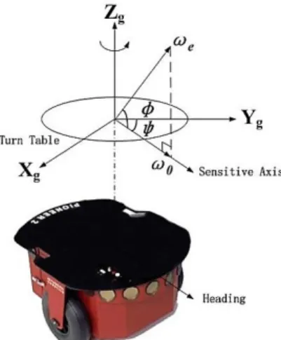
Fig. 1. Geographic coordinate system on the MEMSGyro’s location (geographical latitudeφ).
Fig. 2. Heading detection scheme based on MEMS Gyro north finding approach
and drift can be proved. The experiment results demonstrate effectiveness and performability of the proposed heading detection system.
This paper is organized as follows. Section2 presents the MEMS Gyro north finding theory; the mobile robot heading measurement scheme is also included. The implementation of proposed system will be given in Section3 specifically. Section4 shows the signal processing results and analysis. Section5 mainly discusses the MEMS Gyro North Finding performance and experimental results in prescribed indoor area. To sum up, we give a conclusion in the last Section 6.
2. Theoretical Background 2.1 MEMS Gyro North Finding
As MEMS gyroscope’s accuracy and stability improve nowadays, to accomplish mobile robot’s pointing and targeting mission using MEMS Gyro north finding approach will be a suitable way, due to its low cost, small size and environment adaptability. MEMS gyroscope can sense the angular velocity based on the Coriolis force and its structure. According to this principle, we utilize gyroscope to sense the component of earth’s angular velocity on the sensitive axis. As shown in Fig. 1, a geographic coordinate system is set
up on the MEMS Gyro’s location (geographical latitude φ): Zg, Xg, Yg separately represent the sky direction, the geographical east and north. The gyroscope is fixed perpendicular to the ground, and the sensitive axis is horizontal to the ground. Then MEMS Gyro can provide a ω0, which is the component of earth’s angular velocity ωe on the sensitive axis. Based on this, we can figure out the angle between the initial-time direction of sensitive axis and the geographic north.It is derived specifically in Fig. 2. And if the mobile robot’s forward position is initialized same as the sensitive axis initial-time direction, then the heading angle for the next step movement can be calculated.
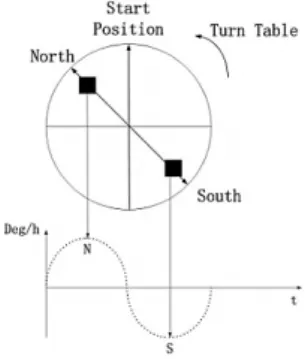
To find out the true north, the Earth’s angular velocity magnitude in a setup location is measured, which is about a maximum of 15°/h. Due to this precision, some forms of error compensation approaches are needed. Sine wave can be applied as the modulated carrier because of its internal continuity and capacity of resisting disturbance. Therefore a rotation table on the mobile robot combined with the earth action is set up to provide a sine wave:
(1)
where ω is the gyro output angular velocity in inertial measurement position according to the turn table
rotation, which is matched to the robot heading position when ω is initial state, ω0. The parameter ωe is the magnitude of the earth’s rotation rate; is the local latitude and represents the angle between the robot heading position and north direction. In this function, it is assumed that the bias and other errors are not considered. This method is shown in Fig. 3.
Fig. 3. Earth and turn table combined action
2.2Heading Angle Measurement
In the ideal situation, gyroscope’s output signal also can be like this:
(2)
Actually, though we apply a turn table to compensate temperature variations and a majority of bias, a complicated zero bias and random walk still existin this signal. So, the factual output signal should be like this [13]:
(3)
Here
∙
In function (2) and (3), E0 is the zero bias; ωt is turn table rotation rate; is the signal to be measured; E1 is the each harmonic component; n(t) represents the drift and noise. Considering about the
filtering performance and calculation conciseness, in this paper we utilize an IIR digital filter to eliminate the drift and noise. In the frequently-used IIR filter, we choose a five order Butterworth filter due to its characteristic and efficiency through MATLAB. After the table rotation calibration and Butterworth filtering, the heading errors are substantially limited by some drift and harmonic component. These errors are eliminated using LSM correlation detection.
To increase the measurement rate, we design a continuous motion north finding method. All the data should be saved during one period in a relative high rate, and then the north finding angle is obtained through the least square parameter estimation. After the filtering, the gyroscope’s output is obtained as:
∙ (4)
where f is the turn table frequency, fs is the sampling frequency, Ni represents the sampling point numbers.
According to the equation (4), it is derivedas
∙
∙ (5)
∙ ∙
And it is defined as
Y = EX (6)
where
⋯
∙∙⋮ ∙∙ ∙ ∙
Mobile Robot
MEMS Gyro
Servo motor
Bluet oot h
Host PC
Encoder Mot or cont rol signal
Heading signal
Fig. 4. Schematic diagram of hardware configuration
Fig. 5. Developed MEMS Gyro north finding system for mobile robot heading detection configuration
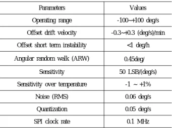
Parameters Values
Operating range -100~+100 deg/s
Offset drift velocity -0.3~+0.3 (deg/s)/min Offset short term instability <1 deg/h Angular random walk (ARW) 0.45deg/
Sensitivity 50 LSB/(deg/s)
Sensitivity over temperature -1 ~ +1%
Noise (RMS) 0.06 deg/s
Quantization 0.05 deg/s
SPI clock rate 0.1 MHz
Table 1. Gyroscope performance specifications The north finding angle is defined as
(7)
3. Implementation of Proposed System
The schematic diagram of the proposed heading detection system is shown in Fig. 4. It is founded on the Pioneer P3-DX robot, which is the most common and popular research platform in robot area. The north finding system consists of a MEMS gyroscope, an AVR board, two Bluetooth serial adaptors, a dc motor for the table rotation, and a host computer. MEMS Gyro’s data is transferred from sensor to the computer by using a Bluetooth because the table turning situation must be under a wireless environment. Turntable servo motor data is processed using a serial interface through the MMC board motor controller. We apply an adaptive Kalman filter to control the rotation motion. Through the host computer, the output heading angle signal is transferred by Serial communication to the wheel encoder. A single axis MEMS gyroscope (SCC1300- D02, VTI Technologies) is chosen for the experiment.
For north finding signal processing about angular velocity, an AVR board is used, which contains an Atmega128 embedded AVR MCU. The turntable is
driven by a servo motor (276550 Brushless servo motor, Maxon Motor ag.) and communicates with host computer through the Bluetooth serial Adaptor (Parani SD100, Sena Technologies, Inc.). The whole system is shown in Fig. 5.
The MEMS gyroscope SCC1300-D02 package consists of a single axis gyroscope and a three axis accelerometer[14]. The turn table leveling error will affect the north finding result: when the turn table has an inclination angle . Due to the perpendicular component influence of the earth angular velocity, , the real result is not the north direction, but the sky and north components composition. And accelerometer can easily measure gravity to find out the roll and pitch. Therefore in the system, the accelerometer is applied to calibrate the platform for the north finding results before data
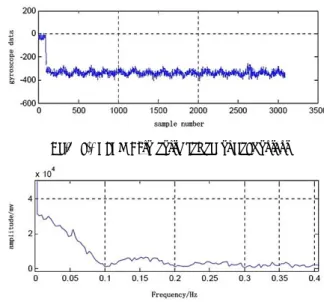
Fig.6 (a). MEMS Gyro north finding original output
Fig.6 (b). FFT analysis of MEMS Gyro north finding original output saving. Besides, the gyroscope’s specifications are given
in Table 1. The resolution and characteristic are suitable for earth rotation detection and even available during high speed movement.
4. Signal Processing Performance
Based on the proposed MEMS Gyro north finding approach, a set of signal processing scheme is designed to achieve the integration with mobile robot movement using the least square method (LSM). Considering about the requests for the navigation time and heading precision, the research specially is focused on the robot’s heading error analyses and north finding elapsed time reduction, which are two of the main factors to affect the accuracy and efficiency. And this signal processing test is implemented on the laboratory table.
The environment temperature is 25℃.
4.1 Digital Filtering
To compensate the temperature drift, the turn table into the system is applied to reduce such kind of bias.
After that, the gyroscope’s original output and its FFT analysis during north finding are shown in Fig. 6 (a) and (b), respectively. From these figures it is shown that, even the output signal performs as a sine wave, the direct current component, sub harmonic and noise still mix with the effective signal, which causes it hard to differentiate. Such kinds of components will strongly influence the heading accuracy. Sampling time and turntable angular velocity also will visibly affect the north finding performance.So actually it is compared with the different kinds of sampling time to match the suitable motor performance. At last, the period for one time north finding we decide is 18 seconds, which is an acceptable interval for the mobile robot application. The sampling time is 10 Hz.
To solve this problem, we design a digital filtering approach through MATLAB. Considering about the filtering result, a conciseness of calculation and output signal’s parameters, we choose a fifth-order Butterworth filter based on the Butterworth theory. The frequency
response of the Butterworth filter is maximally flat in the passband and rolls off towards zero in the stopband[15]. This characteristic is suitable for the gyroscope in this experiment. The performance is clearly shownin Fig. 7. Through the FFT frequency spectrogram shown in Fig. 8it is observed that; the high frequency component has almost been eliminated apparently, but the low frequency component still left.
sample number sample number
Fig. 7. Output signal wave form before and after digital filtering
Fig. 8. MEMS Gyro output signal FFT frequency spectrogram after filtering
Fig. 9. MEMS Gyro output signal before (red) and after (blue) correlation detection
Fig. 10. MEMS Gyro output signal FFT frequency spectrogram after correlation detection
4.2 Correlation Detection
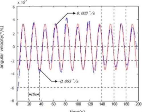
Through the Butterworth lowpass and highpass filtering, the output signal wave form is shown as an approximate sine wave. The signal has some distortion due to the unfiltered low frequency component and drift.
The LSM correlation detection method is utilized to extract an effective signal. From Fig. 9it is shown that, the wave form after the final detectionprocess becomes standard sine wave. The maximum and minimum angular velocities are around 0.003°/s, in good agreement with the horizontal component of the earth’s angular velocity at 35.14° latitude (experiment location).
The frequency spectrogram after correlation detection is shown in Fig. 10. It is proved that the proposed method is enough to eliminate the low frequency component and the drift in order to reserve the effective signal.
Besides, before the experiment for a mobile robot, we use Allan variance analysis method is used to check out gyroscope’s zero bias instability, which is the most
important parameter for evaluate its feasibility[16]. The result can be seen in Fig. 11. The Allan variance of MEMS Gyro after calibration is below 0.1°/h. It has an enough precision for the application of north finding and mobile robot heading detection. And then through the function (4) and (5), the north finding angle is calculated, which will be provided to the mobile robot movement.
Fig. 11. MEMS Gyro output signal Allan variance analysis
5. Experiment Results
The previous experimental setup is followed to carry out the mobile robot heading detection system. The test location is at the mechanical department building in Pusan National University, whose latitude is around north 35.14°. From the calculation it is figured out that the earth’s angular velocity in this position is approximate 12°/h. The MEMS gyroscope is under a sensitive device. To check out the heading detection performance, the selected experiment environment is under a smooth indoor ground without obstacles or slopes. The whole measured platform is observed distinctly in Fig. 12. In order to avoid huge effect from the vibration and shock, the mobile robot moving velocity is set up0.2m/s. And before the movement, the turn table rotates continuously for 10 minutes. This kind of operation can get rid of most of the temperature drift and calibrate the zero point, which are important for the heading accuracy. The gyroscope output data in these ten minutes is shown in Fig. 13.
444.4cm 14.6 °
40 °
N ϕ = North 35.14°
980.0cm
North Finding Position
Fig. 12. Measured platform for mobile robot indoor experiment
Fig. 13. Gyroscope north finding output before movement
Fig. 14. Experimental test using Pioneer robot
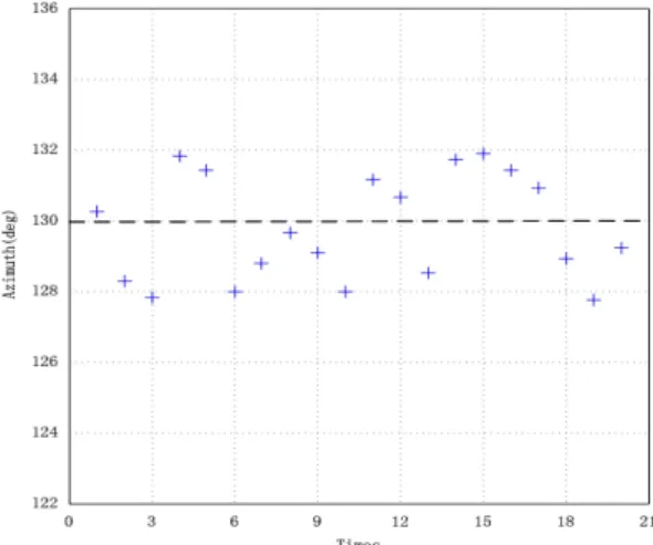
Fig. 15. 20 times heading angle data distribution After moving directly in a 980.0cm distance, the
robot will stop and have one time north finding to figure out the heading angle for the next target pointing.This data is saved for an analysis. Since it is knownthat the target direction is northeast144.6°, the system can calculate the next step rotation information. Fig. 14 shows the realization of robot experiment.
The process is repeated over 20 times to check out the accuracy. During the movement, several kinds of resources will affect the final heading results, such as
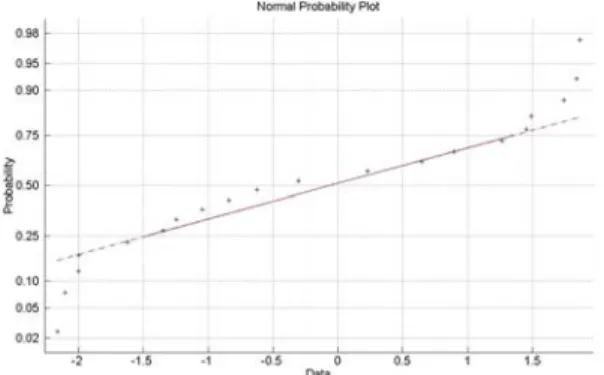
turn table vibration, wheel encoder error and gyroscope error. Therefore when the robot stops at the target, we compare heading angle data with the azimuth is compared up to 20 times in order to evaluate the precision. From Fig. 15it is known that, the average data errors are all between ±3°, which is an acceptable result for the indoor mobile robot application. It makes each time result subtracted to the mean value to get the errors. Through MATLAB Normality test, the heading error distribution can be observed. Fig. 16 shows the final diagram. From the result it isanalyzed thatthe error sample accords with normal distribution approximately.
Fig. 16. Heading error distribution through MATLAB Normality test
6. Conclusion
This paper presented a mobile robot heading detection approach using MEMS Gyro north finding method in the indoor environment. Efficient north finding performance is shown by using a low-cost signal axis gyroscope. Through the LSM filtering method and the turn table rotation, the zero bias, random drift, and other noise has been compensated and the north finding accuracy has improved which was compared with previous researches, the searching time has also been reduced sufficiently.
MEMS Gyro heading detection scheme for mobile robot has been proposed and experimentally validated.
The system feasibility has been evaluated through several times of experiment. From the error analysis it was verified that this method can be applied into the heading detection. However, even the searching time and accuracy have already improved; it is still not suitable for a real-time navigation.
Future work will be focused on decreasing the north searching time through multi-gyroscope integration operations. Also it will be applied to other kinds of filtering method to improve the precision. The various multi sensors fusion approaches will be explored to consummate the data integration. Also some new techniques for this research will be founded to achieve the real-time application.
References
[1] R. Siegwart, and I. R. Nourbakhsh, “Autonomou s Mobile Robots, Introduction”, Cambridge: The MIT Press, London, England, 2004.
[2] S. HERNA’ NDEZ, J.M. TORRES, C.A.
MORALES AND L. ACOSTA,“A New Low Cost System for Autonomous Robot Heading and Position Localization in a Closed Area”, Auto- nomous Robots 15, 99–110, 2003.
[3] J. Borenstein, H. R. Everett, L. Feng, “Where am I? Sensors and Methods for Mobile Robot Positioning”, Univ. of Michigan, April 1996, http://www-personal.umich.edu/~johannb/shared/pos 96rep.pdf.
[4] Taeyeon Kim, loon Lyou,“Indoor Navigation of Skid Steering Mobile Robot Using Ceiling Landmarks”,IEEE International Symposium on Industrial Electronics, 2009.
[5] Ching-Chih Tsai, “A Localization System of a Mobile Robot by FusingDead-Reckoning and Ultrasonic Measurements”, IEEE TRANS- ACTIONS ON INSTRUMENTATION AND MEASUREMENT, VOL. 47, NO. 5, October 1998.
[6] Lindsay Kleeman, “Optimal Estimation of Position and Heading for Mobile Robots Using Ultrasonic Beacons and Dead-reckoning”, Pro- ceedings of the 1992 IEEE International Con- ference on Robotics and Automation, Nice, France, May 1992.
[7] Hakyoung Chung, Lauro Ojeda, and Johann Borenstein, “Sensor fusion for Mobile Robot Dead-reckoningWith a Precision-calibrated Fiber Optic Gyroscope”, Proceedings of the 2001 IEEEInternational Conference on Robotics 8 Automation, Seoul, Korea, May 21-26, 2001.
[8] Marc S. Weinberg, Anthony Kourepenis,“Error Sources in In-Plane Silicon Tuning-Fork MEMS Gyroscopes”, Journal of Microelectromechanical Systems, June 2006.
[9] Burgess R. Johnson, EugenCabuz, Howard B.
French, Ryan Supino, “Development of a MEMS Gyroscope forNorthfinding Applications”, Honeywell
International, 2010.
[10] Lucian loan lozan, MarttiKirkko-Jaakkola, Jussi Collin, JarmoTakala, and CorneliuRusu, “North Finding System Using a MEMS Gyroscope”, Symposium Gyro Technology, Karlsruhe, Germany, 2010.
[11] VTI MEMS Gyro website about north finding application,http://www.vti.fi/en/news-events/press [12] B. M. Renkoski, “The effect of carouseling on
MEMS IMU performance for gyrocompassing applications”, Thesis (S.M.), Massachusetts Institute of Technology, Dept. of Aeronautics and Astro- nautics, June 2008.
[13] Li Denghua, Zhou Feng, Wu Xibao, “Research on two-position north-seeking method based on the Single axis FOG”, Advanced Materials Research Vols. 301-303, Switzerland, 2011.
[14] Datasheet for VTI SCC1300-D02 MEMS Gyro package,http://www.vti.fi/en/products/gyroscopes/co mbined_gyroscope_and_acceleration_sensors/
[15] StephenButterworth, the Butterworth filter, http://e n.wikipedia.org/wiki/Butterworth_filter/
[16] D.W.Allan, the Allan variance,http://en.wikipedia.o rg/wiki/Allan_variance/
Yuanlong Wei 2010 Electrical Engineering,
Beihang University(B.S.) 2010~Present M.S. Candidate,
Mechanical Engineering, PNU
Research Area : Mobile robot localization and Navigation, MEMS sensors
MinCheol Lee 1983 Mechanical Engineering,
PNU (B.S.)
1988 Science and Engineering, Tsukuba University (M.S.) 1991 Applied Physics Engineering,
Tsukuba University (Ph.D) 1991~Present Professor, Mechanical Department, PNU Research Area : Intelligent Robot Control, Path Planning,
Localiztion & Navigation Surgical Robot Control
ChiYen Kim
1999 Mechanical Engineering, PNU (B.S.)
2001 Mechanical Engineering, PNU (M.S.)
2008~Present Ph.D Candidate, Mechanical Engineering PNU 2011~ Present Full-time lecturer, Division of Mechanical
Engineering, Yeungnam College of Science and Technology
Research Area : Surgical Robot, Mechatronics Mechatronics