https://doi.org/10.7848/ksgpc.2019.37.5.379
Enhancement of UAV-based Spatial Positioning Using the Triangular Center Method with Multiple GPS
Joo, Yongjin
1)·Ahn, Yushin
2)Abstract
Recently, a technique for acquiring spatial information data using UAV (Unmanned Aerial Vehicle) has been greatly developed. It is a very crucial issue of the GIS (Geographic Information System) mapping system that passes way point in the unmanned airframe and finally measures the accurate image and stable localization to the desired destination. Though positioning using DGPS (Differential Global Navigation System) or RTK- GPS (Real Time Kinematic-GPS) guarantee highly accurate, they are more expensive than the construction of a single positioning system using a single GPS. In the case of a low-priced single GPS system, the stability of the positioning data deteriorates. Therefore, it is necessary to supplement the uncertainty of the absolute position data of the UAV and to improve the accuracy of the current position data economically in the operating state of the UAV. The aim of this study was to present an algorithm enhancing the stability of position data in a single GPS mode of UAV with multiple GPS. First, the arrangement of multiple GPS receivers through the center of gravity of the UAV were examined. Next, MD (Mahalanobis Distance) is applied to detect instantaneous errors of GPS data in advance and eliminate outliers to increase the accuracy of previously collected multiple GPS data. Processing procedure for multiple GPS reception data by applying the center of the triangular method were presented to improve the position accuracy. Second, UAV navigation systems integrated multiple GPS through configuration of the UAV specifications were implemented. Using the unmanned airframe equipped with multiple GPS receivers, GPS data is measured with the TCM (Triangular Center Method). In addition, UAV equipped with multiple GPS were operated in study area and locational accuracy of multiple GPS of UAV with VRS (Virtual Reference Station) GNSS surveying were compared. The result showed that the error factors are compensated, and the error range are reduced, resulting in the reliability of the corrected value. In conclusion, the result in this paper is expected to realize high-precision position estimation at low cost in UAV using multiple low-cost GPS receivers.
Keywords : UAV, Multiple GPS, TCM, MD
Original article
1. Introduction
Recently, a technique for acquiring spatial information data using UAV (Unmanned Aerial Vehicle) has been greatly developed. In the existing position system such as total station and GPS (Global Positioning System), it is being gradually replaced with unmanned aerial vehicles due to the difficulty of direct measurement in the field with a lot of manpower and time for accurate positioning(Kim, 2018), A DEM (Digital Elevation Model) and a DSM (Digital Elevation
Model) based on an based on an UAV have been developed to analyze the accurate status of road management and facilities (Joo, 2017; Feng et al ., 2014), as well as analysis and accuracy of 3D spatial information (Uysal et al ., 2015; Eker et al .,2018;
Lee and Sung, 2016), Positioning and utilization of spatial information by UAV are superior to conventional methods in terms of speed, economy and convenience. In addition, due to the characteristics of UAV, it is possible to collect current information and analyze and map spatial information for safety prevention and prompt response in disasters
Received 2019. 10. 03, Revised 2019. 10. 15, Accepted 2019. 10. 23
1) Member, Dept. of Aerial Geoinformatics, Inha Technical College (E-mail: [email protected])
2) Corresponding Author, Dept of Civil and Geomatics Engineering, California State University, Fresno, United States (E-mail: [email protected])
This is an Open Access article distributed under the terms of the Creative Commons Attribution Non-Commercial License (http://
areas, where directly access is limited because of many obstacles(Kim et al ., 2014; Shin et al ., 2017; Um, 2018; Kwon et al ., 2019), Especially UAV are becoming increasingly used in environmental and natural disaster monitoring, precise surveying of cultural properties, border surveillance, emergency assistance, search and rescue missions and relay communications (Vacca and Onishi, 2017; Cole et al ., 2009;
Van et al ., 2018; Hayat et al ., 2016; Erdelj et al ., 2017).
It is a very crucial issue of the GIS (Geographic Information System) mapping system that passes way point in the unmanned airframe and finally measures the accurate image and stable localization to the desired destination. The navigation system in UAV not only obtains the current location information of UAV through GPS, but also enables stable flight course and path planning through the setting of the way point (WP) that the unmanned airframe will fly. Positioning using DGPS (Differential Global Navigation System) or RTK-GPS (Real Time Kinematic-GPS) guarantee highly accurate but they are more expensive than the construction of a single positioning system using a single GPS. However, in the case of a low-priced single GPS system, the stability of the positioning data deteriorates. Therefore, it is necessary to supplement the uncertainty of the absolute position data of the UAV and to improve the accuracy of the current position data economically in the operating state of the UAV.
This study aimed to suggest an algorithm enhancing the stability of position data of UAV in a single GPS mode using multiple GPS. Newly designed framework for an unmanned positioning were developed by using a low-cost multiple GPS receiver installed in the UAV, which is enabled to reduce the distance errors by calibrating more accurately the position.
In addition, multiple GPS receivers equipped with UAV are arranged according to the TCM (Triangular Center Method) and operated in the case study area to compare and analyze the position accuracy. To achieve our goal in this study, the research methods and procedures are as follows. First, in chapter 2, we mainly dealt with design of an algorithm for the TCM with multiple GPS. Then, the arrangement of multiple GPS receivers through the center of gravity of the UAV and the error range according to the number of GPS receivers were were examined. Next, we designed processing procedure for multiple GPS reception data and propose a
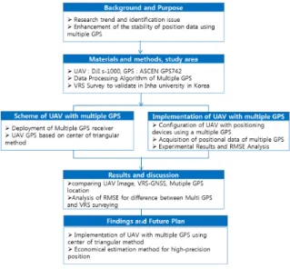
method to improve the position accuracy of GPS by applying the pre-processing process and the center of the triangular method. In chapter 3, we configured the UAV specifications used in the empirical research and suggest implementing UAV navigation systems with multiple GPS to efficiently operate the equipment. Using the unmanned airframe equipped with multiple GPS receivers, GPS data is measured with the TCM. A precision VRS (Virtual Reference Station) receiver surveyed the location of benchmarks selected for the way point within flight capture area to verified coordinate accuracy and stability by comparing data of multiple GPS of UAV and VRS surveying position data. Fig. 1 shows the flow and content of the overall study.
Fig. 1. Overview of study procedure
2. Scheme of UAV with Multiple GPS
2.1 Deployment Design of Multiple GPS Receiver
The GPS data contains various information such as time
and the number of satellites receivable at the latitude and
longitude, the traveling speed, and the moving direction. The
slower speed the UAV moves, the more frequent phenomenon
of the data jumps or the larger the error has. Especially, in
the case of stationary positioning, there are many variables
that are difficult to obtain stable data depending on time
and environment. In addition, due to the characteristics of
the hardware itself, there is a difference in data acquisition
performance between GPS modules. Fig. 2 shows the center of gravity and the error range of the UAV according to the number of GPS receivers (Choi et al ., 2013; Kim et al ., 2013;
Moon et al ., 2008), Fig. 2(a) shows that the circle is assumed to be an error range of GPS, and the triangle in (b) and the rectangle in (c) represent the average error range of the whole receiver through the error range of each GPS receiver. When two GPS receivers are used, the position range is calculated through the average of the two received points, so the error range is wide as shown in Fig. 2 (a), In addition, the direction between two points is instantaneously changed at the moment of rotation, and the position error becomes larger.
the position of the GPS receiver is approximated by using the TCM, so that the error range can be minimized as shown in Fig. 2 (b), In addition, it is possible to estimate the position more flexibly at the moment of instantaneous rotation. On the other hand, if more than four receivers are used, the center of gravity is obtained by using the center of gravity of the triangle as shown in Fig. 2 (c), the variation of the center of gravity becomes large and the error range becomes widened.
Therefore, this increases the instantaneous error in rotation.
Fig. 2. Weighted center and error range of UAV according to the number of GPS
2.2 GPS Receiver based on TCM
In this paper, a system that minimizes the error range considering the number of receivers were designed. The GPS receiver can be arranged in a triangular shape as shown in Fig. 3. Then, the center point where the reception range of the GPS receiver overlaps can be determined as the position of the UAV airframe. When the position of the GPS receiver is approximated by the center of gravity, the error range can be minimized by using the TCM in which three GPS receivers are arranged in a triangular shape. The position can be measured more flexibly even during instantaneous rotation.
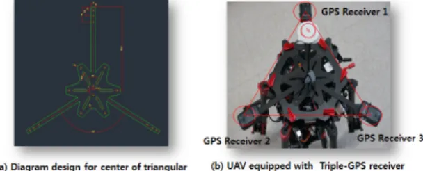
Fig. 3 shows a method of applying the TCM to the arrangement
structure of the GPS receiver in the UAV airframe including the positioning device. Three GPS receivers with one receiver on the front and two receivers on the rear were designed and mounted on a real UAV airframe by applying a TCM. Fig. 3 (a) shows the unmanned airframe with three support fixture and a radial GPS fixed pedestal with the same angle and length of 120 degrees from each other at the center. Fig. 3 (b) shows the arrangement of the GPS receiver in the UAV airframe including the positioning device. The UAV includes three GPS receivers mounted on three support fixtures. GPS receivers are placed in equilateral triangles to receive various data from satellites without error and to reduce interference between GPS receivers. Therefore, the first GPS receiver, the second GPS receiver, and the third GPS receiver are arranged in a triangular shape among them.
Fig. 3. Arrangement of the GPS receives for the TCM
2.3 Data Processing Algorithm of Multiple GPS 2.3.1 GPS Data Reception
When the GPS data transmission starts from the satellite, the GPS data includes information relating to the current position or speed of movement of the GPS receiver and metadata about the GPS data. 1st GPS receiver or 3rd GPS receiver included in the positioning device receives GPS data from at least one satellite. The processor of the positioning device analyzes the received data to the 1st or 3rd GPS receiver. The stability of the GPS receiver is determined by confirming that all data are received at the same time and the number of satellites connected to each GPS receiver is equal to or greater than a predetermined number 4.
2.3.2 Data Preprocessing
In order to increase the accuracy of previously collected
multiple GPS data, MD (Mahalanobis Distance) is applied
to detect instantaneous errors of GPS data in advance
and eliminate outliers. MD has a function in which the standard deviation and the correlation coefficient indicating the properties of a variable are considered together. As a result, more accurate absolute position information can be determined.
(1)
where, i is a gps, is a covariance matrix
If it is determined that the stability is insufficient, the currently received data is excluded from the positioning process and additional GPS data is received from the satellites.
And repeats the process of determining the stability of the GPS receiver from the received GPS data. If the reliability of the GPS is not ensured, the present position can be estimated by using the direction, speed and the direction angle of the moving UAV object at a point where the position is already known. If the position of the unmanned aircraft at time t is known, the position at time t + Δt is determined as follows.
(2)
Also, assuming that the unmanned aerial vehicle makes a straight line motion when flying toward the way point, when the jump phenomenon of GPS data occurs, the position data obtained from the Eq. (2) is greatly deviated. To overcome this problem, the geometrical configuration of latitude and longitude is divided into four parts based on the direction of magnetic north at the present location, and linear regression analysis is performed on the characteristics of GPS data using velocity and azimuth, Respectively. Let Lon be the longitude, Lat be the latitude, t be the time, and a and b are the estimated coefficients, then the least squares method of regression analysis can be used as shown in Eq. (3),
(3)
2.3.3 Correction of Received Position Data After determining whether the data of three receivers are reliable In the previous step, the position is corrected by the center of gravity of the triangle using the position data of the stable moment of each receiver in order to secure the reliability of the data continuously. Eq. (1) is a calculation formula of the position of each GPS receiver and multiple GPS receivers. G is a GPS receiver, and n is the number of satellites measured at the receiver. Here, the position value of the receiver having a large number of satellites is weighted.
If the three receiver data are all good, the center of gravity is determined using the shape of a triangle. If two data are determined to be reliable, the average of the two data is calculated. When only one piece of GPS data is reliable, it takes an independent positioning format and receives data. If the number of satellites in the GPS receiver is less than four, the data is excluded.
(4)
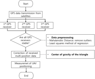
The overall positioning procedure for UAV with multiple GPS receivers as shown in Fig. 4
Fig. 4. Positioning procedures for multiple GPS receivers
3. Implementation of UAV with Multiple GPS
3.1 Configuration of UAV with Positioning Devices Using a Multiple GPS
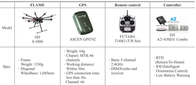
Table 1 shows the configuration of a UAV with positioning devices of a multiple GPS used in this study. The frame of the UAV used in this study is DJI S1000 model and includes 8 propellers and landing gear which can be folded in flight.
One propeller output is up to 2.5kg and can be operated with a maximum weight of 20kg. The GPS receiver consists of ASCEN GPS742 with a single positioning error of less than 10 meters. The controller adopts DJI's A2 controller and iSOD II video transceiver, which are products of the same company, in consideration of convenience and compatibility between products. We used two units of the Futaba T14SG controller for UAV handling and camera operation. The camera was determined to be Panasonic's GH4 with 16 million pixels.
Fig. 5 shows the UAV equipped with multiple GPS by TCM implemented in this study. As shown in Fig. 5(a), we equipped the unmanned aerial vehicle with a radial GPS fixed pedestal that included support fixture with three identical length at 120 degrees from each other in the center.
The GPS fixture includes a plurality of openings into which a screw or bolt can be inserted. It also includes a number of supports of the same length that are spread at a certain angle.
The radial GPS fixed mount is physically connected to the body of the unmanned aerial vehicle. Pedestal of the radial GPS is fixed to the upper end of the unmanned frame, and connects the body of the UAV as shown Fig. 5(b), Multiple GPS receivers were mounted on the three support fixture of the GPS installed in the unmanned airframe as shown Fig.
5(c), The three GPS receivers were installed on three support fixture extending from the center of the unmanned airframe as shown Fig. 5(d), Under the elongated support structure, the GPS can receive radio waves without interference from other equipment in the unmanned aerial vehicle. In order to ensure safety distance, the propeller included in the unmanned airframe was designed with a GPS device and a long extended GPS receiver as shown Fig. 5(e), The GPS receiver is located outside the turning radius of rotation of the propeller. A GPS receiver is positioned between the turning radius formed by the multiple propellers. Fig. 5 (f) is the final assembly of unmanned airframe with multiple GPS including the positioning device extends in three directions from the center by TCM.
FLAME GPS Remote control Controller
Model
S-1000 DJI ASCEN GPS742 FUTABA
T14SG (T/R Set)
A2+iOSDⅡ Combo DJI
Spec.
∙ Frame Weight:1330g
∙ Diagonal
Wheelbase:1,045mm
∙ Weight: 64g
∙ Chipset: MTK 66 channels
∙ Working distance:
Within 10m
∙ GPS connection time:
less than 36s Channel: 66
∙ Basic 5-channel 2.4GHz
∙ DSMXradio and receiver
∙ RTH
(Return-To-Home)
∙ IOC(Intelligent Orientation Control)
∙ Low Battery Warning
Table 1. Configuration of UAV
(a)
(c)
(b)
(d)
(f) (e)
Fig. 5 UAV assembly of multiple GPS by TCM
3.2 Acquisition of Positional Data of Multiple GPS In order to improve the accuracy of UAV 's outdoor single location estimation, we used the position of the TCM using multiple GPS above mentioned in 3.1 compensating the positional information of single GPS with relatively large error. For the experiment, coordinates were obtained for the roads inside Inha University. The coordinates of GPS and the location of GCP are as shown in Fig. 6.
Fig. 6. Study area
Fig. 7 shows that multiple GPS data of the unmanned aerial vehicle captured by the flight and the position data of the VRS GNSS surveying to be converted and displayed on the GIS map. Fig. 7(a), (b) and (c) show reception logs of three individual GPS, and Fig. 7(e) Three GPS receivers were used
to obtain the positional information corrected by the TCM.
A total of 26 GCP locations as a benchmark for way points in the unmanned aerial photographing area were obtained by using VRS surveying receiver (Kolida K9-T) as shown in Fig. 7(f),
(a) GPS Receiver 1
(d) GPS Receiver 1&2&3
(b) GPS Receiver 2
(e) CTM
(c) GPS Receiver 3
(f) VRS (Virtual Reference Station)