* 인하공업전문대학 기계공학부 기계설계과 주소: 402-752 인천광역시 남구 인하로 100
⌧ Corresponding Author E-mail: [email protected]
Mechanical Design of Ring Laser Gyroscope Using Finite Element Method
Jeong Ick Lee*
(Manuscript received: Aug, 7, 2012 / Revised: Sep, 22, 2012 / Accepted: Sep, 22, 2012)
링 레이저 자이로스콥을 위한 유한요소법 기계 설계
이정익*
Abstract
The gyroscopes have been used as a suitable inertial instrument for the navigation guidance and attitude controls. The accuracy as very sensitive sensor is limited by the lock-in region (dead band) due to the frequency coupling between two counter-propagating waves at low rotation rates. This frequency coupling gives no phase difference, and an angular increment is not detected. This problem can be overcome by mechanically dithering the gyroscope. This paper presents the design method of mechanical dither by the theoretical considerations and the verification of the theoretical equations through FEM applications. As a result, comparing to the past result(4), the maximum prediction error of resonant frequency was within 3 percent and peak dither rate was within 5 percent. It was found that the theoretical equations can be feasible for the mechanical performance of dither.
Key Words : Ring laser gyroscope(링 레이저 자이로스콥), Lock-in region(폐영역), Dead band(사영역), Mechanical dither(기계적 디더), Resonant frequency(공명 진동수), Torsional stiffness(비틀림 강성), Peak angular amplitude(피크 각 진폭), Peak dither rate(피크 디더 레이트), Finite element method(FEM, 유한요소법)
Nomenclature
P : Shear force M : Bending moment E : Modulus of elasticity I : Moment of inertia of area J : Polar moment of inertia of mass
: Circumferential deflection of spoke fn : Resonant frequency
: Bending stress of spoke ε : Longitudinal strain of spoke
max: Peak dither rate
1. Introduction
When there is an applied rotation about the axis normal to the plane of rotation, the operation of gyroscope depends on the phase difference for beams traveling in opposite
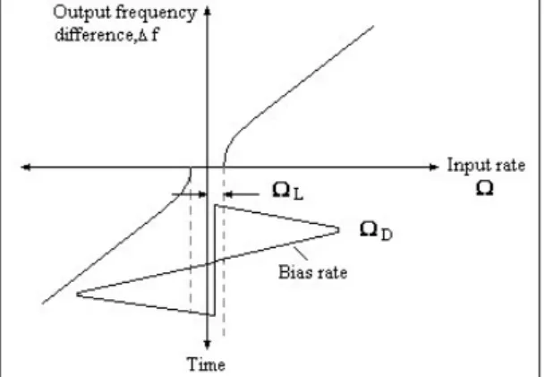
Fig. 1 Laser gyroscope alternating bias technique
Fig. 2 Dither spoke geometry
direction within a closed path. This difference gives rise to a phase difference. But the accuracy of gyroscopes has been limited by the lock-in region due to the fact that at low rotation rates of gyroscope the frequency coupling mechanism arises from back scattering of the mirrors. This effect gives no phase difference and hence no detect of angular increment.
In other words, this reduces the angular sensitivities to the electrical and mechanical disturbances such as low frequency noise components, in the optical measurement. It is important to minimize the transition periods of lock-in region. The dithering motion is to operate the gyroscope under the lock-in region in order to be sensitive against input rotation rates which are below that certain region (Fig. 1). The dithering method uses the electrical signal processing for the low back scatter in conjunction with a stable gas discharge, a suitable dither drive and a stabilized resonator cavity length. But the simplest dithering method is to use the mechanical dither(1,3~5).
The purpose of the mechanical dithering is to suppress the dead band, oscillate the block about the rotation axis and add an external rotation rate. The design considerations
of mechanical dither include the followings : structural resonant frequency, peak angular amplitude and dither rate, driving technique, and inertia of dithered components.
The formulation of mechanical dither was explained by Shackleton B. R. in 1987(4). His paper presented the geo- metrical approach of spoke, but had no considerations of the loading condition and angular characteristics due to the piezo element deformation.
In this paper, the mechanical performances of dither are theoretically presented on the basis of any loading condition and angular characteristics (peak dither amplitude and rate) due to the piezo element deformation. And using the transverse vibration behavior of elastic spoke, the resonant frequency of mechanical dither is calculated. Through the finite element analysis, the structural performances of mechanical dither are compared.(2)
2. Mechanical Performance of Dither
The aforesaid mono block system is assumed to be mounted on the outer diameter R1 of spoke. But if a spoke has the end mass m at a point R1, the resonant frequency for the mounting location of mono block system at an arbitrary point L' on the spoke may be given by,
′
(1)
where n is the number of elastic spokes, Kθ is the torsional stiffness of the dither from Eq. (6), Jsys is the polar mass moment of inertia of the dithering system, L is the swing arm of spoke assumed as R1- R2. The relationship between m and Jsys is given by
′
for a spoke.
Since both ends of spoke are respectively built at the central post and mono block, the bending stresses at the ends must to be verified within the allowable stress. Using Eq. (9) and setting x = 0, the bending stress at R2 is given by,
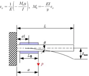
Fig. 3 Spoke deformation due to bending moment
(2-a)
and can be rewritten, and t = d / 2
(2-b)
Also, the torque can be written in terms of the geometric parameters and mechanical properties,
(3-a)
(3-b)
Hence the bending stress may be expressed in terms of the geometry of the spoke and the angular deflection.
3. Loading Condition
The mechanical dither is mounted via the beam-shaped spokes to the gyroscope mono block and to the inertial rigid reference frame. The deformation of spoke is under the alternate deformation of piezo element on both faces. Each opposite voltage signal on two faces is loaded and results in the compression and expansion deformations of spoke.
The bending behavior of spoke due to the stretching and contracting deformations of piezo element is shown in Fig. 3.
The longitudinal strain εx of spoke and the bending moment are given by,
ε
,
ε
(4)
Setting the maximum strain εx≈ ΔL / L0 at the piezo element bonding face (y = d / 2), the bending moment of spoke may be given by,
(5)
on the neutral axis, where L0 is the length of piezo element, d is the thickness of spoke, ΔL is the maximum deformation of piezo element along the longitudinal direction.
Since the maximum deflection due to a moment Mb or a vertical load P must be equal at the end, the equivalent force is given as,
max
(6)
(7)
The bending angle θa at the loading point a is approxi- mated as the peak angular amplitude.
(8-a)
And from the condition that the maximum external work is equal to the maximum kinetic energy, the peak dither rate may be given by,
max max
max
max
(8-b)
where δa is the vertical deflection at the loading point a.
4. Simulation
The primary goal of the finite element analysis is to guide the structural design of dither. A typical simulation of the dynamic behavior based on the structural stiffness of the dither system takes into account two aspects: the first is the
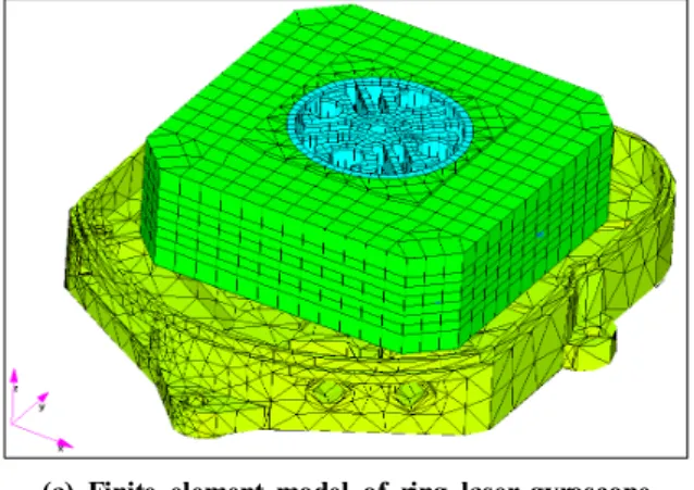
(a) Finite element model of ring laser gyroscope
(b) Resonant frequency of typical mechanical dither Fig. 4 Schematic model of ring laser gyroscope
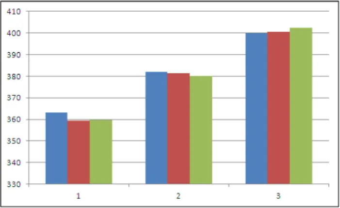
Table 1 Resonant frequencies of mechanical dithers to thickness variations
No Thickness d (mm)
Test Freq. (Hz) Peak dither rate(deg/sec)
FEA Freq. (Hz) Peak dither rate(deg/sec)
Theoretical Eq.
Freq. (Hz), Peak dither rate(deg/sec) 1 2.94 363.00,
134.15
359.54, 137.25
359.77, 137.19 2 3.08 382.00
145.10
381.23, 141.61
380.07, 144.24 3 3.22 400.00
150.00
400.44, 143.52
402.50, 147.03 mode at the detection space of gyroscope and the second
is the frequency history of the angle in the desired direction referred to as the dither amplitude.
The radial dither in Fig. 4-(a) is mounting via four wedge- shaped spokes to the gyroscope solid block and to the inertial reference frame which is rigid. The bending moment of a spoke under the driving deformation of piezo element (ΔL = ±2μm) may be calculated from Eq. (15). From Fig.
2 and 3, the shape parameters of a spoke in Fig. 4 are as follows: n = 4, R1= 19.25mm, R2= 5.00mm, L' = 10.50mm, w = 30.00mm, a = 6.25mm, a1= 4.00mm. From Eq. (19), the equivalent polar mass moment of inertia of system is 1.66 ton-mm2 except the grounded constituent components, based on the test resonant frequency (fsys= 382Hz) and the inertial effect of system is taken into account as the scalar dummy inertia. This equivalent mass moment of inertia of system
may be used for representing the inertial effect of the dithering structure. If the resonant frequency is basically given, the equivalent polar mass moment of inertia (Jsys) may be approximated as follows,
≈
(9)
where fdither is the natural frequency of mechanical dither structure without the consideration of mono block system, which is 4897.12Hz as shown in Fig. 4-(b) and fdither is the mass moment of inertia of mechanical dither., which is 0.01095ton-mm2 .
The structural damping factor is given as Q - factor (Q
= 1/2ζ ), which is 150. The material properties are given as INVAR 36 ALLOY (E = 144.9GPa, v = 0.29, ρ = 8.11×10⁻⁶ kg/mm3).The four spokes are constrained for the connection with the rigid inertial reference frame. For 8-node hexa- hedron solid element model of mechanical dither, the peak dither rate and resonant frequency are simulated through the direct frequency response analysis, using MSC/NASTRAN V70.5. Table 1 shows the 1st resonant frequency for the rotational mode and peak dither rate.
In Table 1, the results of the finite element analyses and numerical solutions show that the maximum relative errors to test results are within 3 percent in the resonant frequency and 5 percent in the peak dither rate, and two methods are relatively available for designing the mechanical dither. Fig.
5 shows the resonant frequency comparisons of Test, FEA and theoretical equation of mechanical dithers to thickness variables (when 2.94, 3.08 and 3.22). But the difference rate is not over 3 percent. Fig. 6 also show the peak dither rate comparisons of Test, FEA and theoretical equation of
Fig. 5 The resonant frequency comparisons of Test, FEA and Theoretical Equation of mechanical dithers to thickness variables(1=2.94mm, 2=3.08mm and 3=3.22mm)(blue:Test, red:FEA, green:Theoretical)
Fig. 6 The peak dither rate comparisons of Test, FEA and Theore- tical Equation of mechanical dithers to thickness variables (1=2.94mm, 2=3.08mm and 3=3.22mm)(blue:Test, red:FEA, green:Theoretical)
mechanical dithers to thickness variables (when 2.94, 3.08 and 3.22). But the difference rate is not over 5 percent.
From the aforesaid equations, it can be known that the relative error between finite element analyses and theoretical solutions depend on the working elastic length, which is given as L
= R1- R2. This working elastic length is the effective bending length under the bending deformation of a spoke.
5. Conclusion
From the geometric parameters and material properties of
the dither, the mechanical characteristics can be given as follows: torsional stiffness, bending profile, points of inflection, stress caused by bending of the spokes, resonant frequency and peak dither rate. And since the stress within the spoke and piezo element may further limit the angular amplitude and rate, the peak dither rate is usually limited to the angular amplitude which did not cause stresses in the spoke material to exceed the effective material stress. The effective bending length as the working elastic length is the important factor which has an influence on the angular deflection as the bending deformation of spoke. But the geometrical parameters of spoke can approximately be used. And the finite element analysis can be used for designing the concrete and complicated spoke within the given design range.
References
(1) Kline-Schoder, R. J., Wright, M. J., 1992, “Design of a Dither Mirror Control System,” Mechanics, Vol. 2, No. 2, pp. 115~127.
(2) Craig, R. R., 1981, Structural Dynamics an Introduction to Computer Methods, John Wiley & Sons, New York.
(3) Schleich, W., and Dobiasch, P., 1984, “Noise Analysis of Ring Laser Gyroscope with Arbitrary Dither,” Optics Communications, Vol. 52, No. 1, pp. 63~68.
(4) Shackleton, B. R., 1987, “Mechanical Design Conside- rations for a Ring Laser Gyro Dither Mechanism,”
Proceeding Instrument Mechanical Engineering, pp.
105~112.
(5) Hutchings, T. J., 1978, “Scale Factor Non-linearity of a Body Dither Laser Gyro,” Proc. IEEE Nat'l Aerospace and Electronic conference, pp. 549~555.
(6) Cho, H. Y., Kim, K. W., Kim, D. B., Sin, H. S., Kim, W.
Y., and Park, J. K., 2012, “Finite Element Analysis for Laser Polishing,” 2012 Proceedings of the Korean Society of Manufacturing, pp. 29.
(7) Lee, Y. C., 2008, “A Study on the Mechanical Design and the 2.5-axile Combined Machining by CAD/CAM,”
Transaction of the Korean Society of Manufacturing Technology Engineers, Vol. 17, No. 6, pp. 97~103.