Vol.14, No.4, pp.18-24 (2020)
Drag Reduction Effect by Counter-flow Jet
on Conventional Rocket Configuration in Supersonic/Hypersonic Flow
Yongchan Kim
1, Duk-Min Kim
1, Tae-Seong Roh
1and Hyoung Jin Lee
1,†1
Department of Aerospace Engineering, Inha University
Abstract
The counter-flow jet from a supersonic/hypersonic vehicle causes a structural change in the shock wave generated around the aircraft, which can lead to reduced drag and heat loads. Since the idea is to mount a counter-flow jet device for drag reduction in the aircraft, it is necessary to understand the effect of such a device on the entire aircraft. In this study, the effect of drag reduction due to counter-flow jet on a conventional rocket configuration was analyzed through CFD analysis. The results showed that the drag reduction effect was the largest in the blunt region and that the counter- flow jet also affected the downstream of the aircraft. The analysis indicated that the drag reduction effect by the counter-flow jet was about 10 to 25 % when targeting the entire rocket-shaped area, while the effect was as high as 50% when targeting only blunt objects.
Key Words: Drag Reduction, Counter-flow Jet, Supersonic/Hypersonic Flow, Rocket
1
1.. IIn nttrro od du uc cttiio on n
Recently, aircrafts have reached speeds in the hypersonic region beyond the supersonic region, and various efforts have been made to reduce the drag of such aircrafts to increase their propulsion efficiency. Counter-flow jet, one of the various methods for drag reduction, involves injecting a gas toward the freestream to cause flow interactions between the jet and the bow shock, where both drag and heat reduction effects can be obtained simultaneously. Therefore, the counter-flow jet is considered the most efficient technique for drag reduction, and various studies have employed numerical and experimental approaches to analyze the effect of the counter-flow jet condition on the drag and heat reduction.
Previous studies have mainly examined the factors affecting drag reduction caused by a counter-flow jet and observed their effects or analyzed the flow structure caused by the counter- flow jet. For example, Finley [1] observed the surface pressure distribution by changing the nozzle outlet Mach number, the nozzle-base area ratio, and the counter-flow jet and freestream total pressure ratio on the hemispherical shape, and the author confirmed that the drag and thermal load reduction effect increased as the total pressure ratio increased. Shang [2]
analyzed the drag force in terms of the total pressure ratio
using a plasma jet through experiments and numerical analysis.
The author found that there is a critical pressure ratio at which the drag force is minimized, and that the flow structure can be classified based on this value. Hayashi [3] analyzed the effect of heat reduction with changes in the nozzle outlet Mach number, the nozzle outlet diameter, and the total temperature of the jet gas at the same mass flow rate using a nitrogen gas.
Their results showed that a lower heat reduction effect is obtained with a smaller nozzle outlet Mach number, a larger nozzle outlet diameter, and a smaller total temperature of the injection gas. Tatsumi [4] theoretically analyzed the point at which the total axial force coefficient is at its minimum value.
Venukumar [5] conducted computational simulations to show the tendency of drag reduction according to the pressure ratio by using a helium and nitrogen gas and confirmed that the drag reduction rate could remain constant when the pressure ratio was above a certain value. Daso [6] performed experiments and numerical simulations to analyze the tendency of drag and heat reduction with variations in the nozzle outlet Mach number, nozzle outlet diameter, injection flow rate, and angle of attack, and they observed the flow structure by jet mass flow rate. Yisheng [7] established RPA as a new parameter combining total pressure ratio and jet flux and obtained the drag reduction effects with changes in the various parameters through numerical simulations. The author found that as the RPA value increases, the drag reduction rate increases, and the same drag coefficient is obtained at the Received: Mar. 26, 2020 Revised: Jun. 10, 2020 Accepted: Jun. 19, 2020
† Corresponding Author
Tel: +82-32-860-7355, E-mail: [email protected]
Ⓒ The Society for Aerospace System Engineering
same RPA value. Bibi [8] applied a diverging nozzle for a counter-flow jet and analyzed the drag and flow structure in terms of the pressure ratio and confirmed that the drag reduction effect of the diverging nozzle was greater than that of the sonic nozzle. Recent studies have examined combinations of various methods for drag reduction. For example, Xi [9] observed the drag reduction effect in terms of the combination of the cavity and counter-flow jet, and Ou [10]
observed the drag reduction effect in terms of the combination of a spike and a counter-flow jet, then analyzed the drag reduction mechanism. Kim et al. [11] identified counter-flow jet factors that have a dominant effect on drag reduction and analyzed the drag reduction tendency through various factors.
They also confirmed that a high drag reduction effect could be obtained with a low mass flow rate when considering the combined effect of design parameters.
Most of the previous studies examining drag reduction observed the counter-flow jet flowfield and analyzed the effects of various parameters, but the model geometries considered only consisted of blunt objects such as hemispheres, cones, and ogives. The reason for this is that the drag force is particularly large on the blunt part of the nose cone, and the previous studies have mainly been performed as fundamental studies aimed at observing or analyzing the flowfield by the counter-flow jet, not as system applications of the aircraft. However, since the ultimate aim is to install a counter-flow jet device for drag reduction in the aircraft, it is necessary to understand the drag reduction effect of the counter-flow jet on the overall aircraft, not just on any single part such as the nose, and examine the installation possibilities.
In addition, since a drag force acts on the whole aircraft, the drag reduction effect may be smaller than the overall drag force, even if the drag reduction effect on the only blunt object is large.
In this study, CFD simulations were performed to investigate the drag reduction effect by the counter-flow jet on the conventional rocket configuration. The drag reduction effect was analyzed on the entire aircraft as well as on each part of the aircraft, and the potential effect of the counter-flow jet device was confirmed.
2
2.. N Nu um me erriic ca all a ap pp prro oa ac ch h
2
2..1 1 N Nu um me erriic ca all m me etth ho od ds s a an nd d g ge eo om me ettrry y
In this study, the computational analysis was conducted using commercial CFD software (Star-CCM+ 14.02). A density-based coupled solver was used for the two- dimensional axisymmetric steady-state RANS equation. To ensure the reliability of the simulation results, the numerical methods were applied through the same technique used in the previous study [11]. The Advection Upstream Splitting Method (AUSM+) technique was applied to the inviscid convection term, and the 3rd order Monotomic Upwind
Scheme for Conservation Laws (MUSCL) was applied to spatial difference. The working fluid was an ideal gas, in which the viscosity and specific heat were calculated using Sutherland’s law and the polynomial in T conditions. For a turbulence model, the k-w SST model was used, and compressibility correction was applied. The wall condition was set to the non-slip isothermal condition, and the Y+ value at the wall satisfied the constraint of the value being 1 or less for accurate analysis of the turbulent boundary layer.
The model geometry was a conventional rocket shape with a blunt-conical nose, which was configured with TAHHD, as presented in Fig.1 [12]. The freestream and counter-flow jet conditions are listed in Table 1. The flight altitude was selected so that the same stagnation pressure would be preserved at different flight Mach numbers. Hypersonic aircraft can only operate at high altitudes where the total temperature of the freestream increases more than the 2000 K, in which the dissociation of the air molecules can occur. While this can affect the aerodynamic characteristics of the aircraft, it is not considered in this study. The nozzle of the counter-flow jet has an exit diameter of 9.0 mm, a Mach number of 3.0, and an injection pressure that is adjusted by PR. The PR is the stagnation pressure ratio of the freestream and the counter- flow jet, which is defined below.
= ,
, (1)
Fig. 1 Physical model [12]
Table 1 Freestream and counter-flow jet condition
M∞ 4.0 7.0 10.0
Altitude [km] 17.8 40.0 58.2
P0,∞ [bar] 11.9
P∞ [pa] 7829.1 287.1 28.0
T∞ [K] 216.65 250.35 251.99
Mj 3.0
PR (P0,j/P0,∞) 0.4, 0.8, 1.2, 1.6, 2.0
2
2..2 2 V Va alliid da attiio on n
The numerical methods were validated through grid dependency and comparative analysis with previous experimental results, and the details are presented in a previous study [11].
Figure 2 shows the validation results [11], which consist of
Fig. 2 Validation results
the Stanton numbers on the surface obtained through the experiments and computational simulations in PR 0.6, and the geometry differed from that of this study. The results of both the SA model and the k-w SST model showed levels of error similar to that of the experimental results, but it was confirmed that the results of both turbulence models were more similar to the experimental results compared to the previous study.
Compared with the previous experimental results [3], the two models showed similar differences, but in the center of the body, where the influence of the counter-flow jet is relatively large, the k-w SST model is in better agreement with the experimental results. Therefore, the k-w SST model was selected in this study.
3
3.. R Re es su ulltts s a an nd d d diis sc cu us ss siio on n
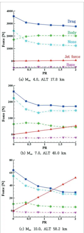
The drag is the force acting opposite to the direction of the aircraft moving, and it can be divided into pressure drag, surface friction drag, wave drag, and lift-induced drag. In the case of a supersonic/hypersonic vehicle, the drag force by the pressure is the main acting force, and the counter-flow jet only affects the pressure drag. Since the counter-flow jet for drag reduction is injected in the moving direction of the aircraft, the force generated by the gas injection acts in the opposite direction. Therefore, the total drag force of the aircraft with the counter-flow jet is equal to the total axial force, which is the sum of the force acting by the surface pressure and the force generated by the counter-flow jet. In this study, the force acting by the surface pressure is referred to as drag, the force caused by counter-flow jet is expressed as jet force, and the axial force acting on the entire aircraft is considered the sum of drag and jet force. As shown in Fig. 1, the force with the PR was compared by dividing the blunt-conical part into the nose, body, and base, which are the parts where the force mainly acts on the surface. The relationship between the forces examined in this paper can be summarized as follows.
Total axial force = Drag + Jet force
Drag = Nose force + Body force + Base force
Fig. 3 Force comparison at different flight conditions 3
3..1 1 C Co om mp pa arriis so on n o off d drra ag g ffo orrc ce e ffo orr e ea ac ch h p pa arrtt
Figure 3 shows the force change of each part caused by the counter-flow jet at each flight Mach number. For each Mach number, the magnitude of the jet force is the same. When the flight Mach number is 4.0, the drag is greater than the jet force, because the flight altitude is relatively low at 17.8 km,Fig. 4 Results at M
ꝏ4.0, ALT 17.8 km
where the atmospheric density is high. As the flight Mach number increases, the altitude also increases while the basic drag force decreases, which causes the magnitude of the drag force and the jet force to gradually become similar. In terms of the drag change with PR, it is observed that the drag acting on the surface decreases as the PR increases, regardless of the flight Mach number, which is a typical feature of the drag reduction phenomenon caused by the counter-flow jet.
As shown in Fig. 3, the drag reduction due to the counter- flow jet occurs mainly in the nose region. Regardless of the flight Mach number, as the PR increases, the drag on the nose part decreases continuously. The same tendency of drag reduction is also observed at the total drag, indicating that the drag reduction on the nose region is dominant for total drag.
By contrast, the drag by the counter-flow jet is insignificant at both the body and the base part, which are relatively far from the counter-flow jet nozzle. However, the drag force of the body is relatively larger than that of the base, and the drag of that increases when the PR is 0.4, regardless of the flight
Fig. 5 Mach number contour of No-jet and PR 0.4 cases at M
ꝏ4.0, ALT 17.8 km
Mach number, which is caused by the change of the flight Mach number around the aircraft.
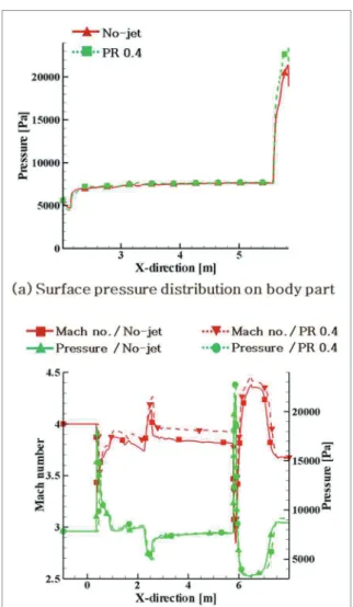
Figure 4(a) shows the pressure distribution on the surface, while (b) represents the pressure and Mach number distribution at a distance of 0.3 m from the surface. In Fig.
4(a), the pressure of the body part remains constant, and a slight difference is observed at the end, where the oblique shock wave occurs due to the flare part. In Fig. 4(b), the pressure differs only at the rear end of the body, as there is little difference at the head, whereas the Mach number shows a substantial difference.
Figure 5 shows the Mach number and pressure contour at the rear end of the aircraft. The black dotted line is the area where the Mach number and the pressure were measured, and the difference in Mach number caused by the counter-flow jet can be observed. When the counter-flow jet is injected for drag reduction, the bow shock at the front end is deformed, and the strength of the shock wave is also weakened, causing the Mach number at the downstream of the shock wave to increase.
The total pressure loss is reduced due to the weakened shock wave, but the Mach number increases, which results in the static pressure of the flow being maintained at a constant level.
In addition, the pressure downstream of the oblique shock increases as the upstream Mach number increases. Since the freestream pressure is the same, the downstream pressure of
the oblique shock is higher when the Mach number is high due to the counter-flow jet. As a result, the drag of the body increases.
3
3..2 2 C Co om mp pa arriis so on n o off d drra ag g ffo orrc ce e a att n no os se e rre eg giio on n
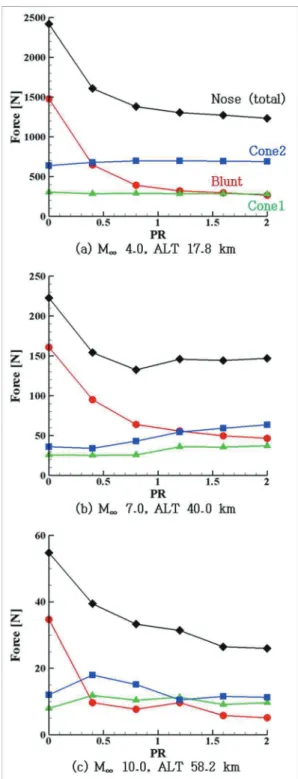
The results presented in section 3.1 confirmed that the effect of the nose part was dominant for the change in total drag force. In section 3.2, the effect of drag reduction was compared across the divided areas constituting the nose. The nose part is composed of blunt, cone 1, and cone 2, as shown in Fig. 6.
Figure 7 shows the drag force for each area of the nose.
When the flight Mach number is 4.0, the change in the drag force with increasing PR is very slight, and the value remains constant at cone 1 and 2, whereas it is substantial at the blunt area. Since the drag reduction trend at the blunt is the same as that of the entire nose, the blunt region has the most dominant effect on the drag reduction in the nose. However, for the flight Mach numbers of 7.0 and 10.0, the drag force in the cone part changes as PR increases. At the flight Mach number of 7.0, the drag also increases above PR 0.8. at the flight Mach number of 10.0, the drag increases at PR 0.4 and decreases again above PR 0.8. The cause of the change in drag at the cone can be determined by comparing the flowfield.
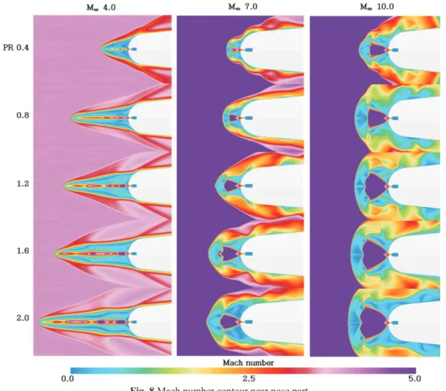
Figure 8 shows the Mach number contour, and a difference in flow structure can be observed with PR. The deformation of the shock wave due to the counter-flow jet is similar to that presented in the previous study [11]. Depending on the flight Mach number and PR, an LPM (Long Penetration Mode) or SPM (Short Penetration Mode) structure can occur, as the penetration length increases as the PR increases. When the flight Mach number is 4.0, the LPM structure appears regardless of the PR, and the impact of the shock wave deformation is limited only to the blunt part, so the change in drag occurs only in that part as well. On the other hand, when the flight Mach numbers are 7.0 and 10.0, the SPM structure is observed in every PR, and the counter-flow jet affects not only blunt but also cone. When the PR of the counter-flow jet is low, the shock wave deformed by the counter-flow jet affects the cone part, and the surface pressure increases due to the unstable flow characteristics, while the drag also increases.
However, when the PR increases, the cone part is free from the influence of the deformed shock wave, and the pressure and the drag at the cone decrease. In addition, even if the same SPM structure appears at the same PR, the size and penetration length of the counter-flow jet are different when the flight Mach number is different. This is caused by the difference in the momentum ratio between the freestream and counter-flow jet [11], and the range of counter-flow jet expands as the momentum ratio increases.
Fig. 6 Different shapes of nose part
Fig. 7 Force comparison for nose part
3
3..3 3 C Co om mp pa arriis so on n o off tto otta all a ax xiia all ffo orrc ce e
Based on the results presented in sections 3.1~2, the total axial force with varying PR was compared. The axial force for each flight Mach number was expressed as the drag ratio with respect to drag without jet. When the flight Mach number is 4.0, the axial force continuously decreases as PR increases, but when the Mach numbers are 7.0 and 10.0, the axial force decreases until PR 0.8, then increases again when the PR is above 0.8. When PR is 1.2 or more at the Mach number of 10.0, the drag ratio increases and exceeds 1, which means that the drag reduction effect caused by counter-flow jet disappears.
As the PR reaches a specific value, which varies depending on the flight conditions, the amount of increase in the jet force exceeds that of the decrease in the drag force, causing the total axial force to increase again. This phenomenon was observed in the previous study [11], where it was defined as a thrust reversal phenomenon. The total axial force is minimized at the point where the reversal occurs, and when the counter-flow jet pressure is larger than this, the axial force increases again.
Fig. 9 Total axial force ratio
The maximum drag reduction rate is 21% at the flight Mach number of 4.0, 25% at 7.0, and 7% at 10.0. When the flight Mach number is low, the drag reduction effect is larger at higher PR, and as the Mach number increases, a high drag
Fig. 8 Mach number contour near nose part
reduction effect exists at low PR, but the thrust reversal phenomenon easily occurs. Even if the jet force is the same, the drag reduction effect can differ because the drag that basically acts varies with the flight Mach number and altitude.
As a result, it is necessary to adjust the counter-flow jet pressure to the particular flight conditions.
4
4.. C Co on nc cllu us siio on n
In this study, the drag reduction effects by a counter-flow jet on a rocket with the conventional shape were examined. The possibility of a practical counter-flow jet device was examined by analyzing the drag reduction effect of the entire aircraft under various operating conditions. The results show that the drag reduction effect due to the counter-flow jet is dominant at the nose part, and a higher drag reduction effect occurs when the shape is blunt. In addition, when only the blunt shape was considered in the previous studies, the drag reduction effect was reported to be up to 30~55%. However, in this study it was confirmed that a 7~25 % drag reduction effect could be obtained when considering the overall shape of the aircraft.
Although the possibility of installation in actual aircraft was confirmed, factors such as loss due to the additional weight still need to be considered. In a future study, the drag reduction effect should be analyzed in consideration of the air reaction under high temperature conditions.
A
Ac ck kn no ow wlle ed dg ge em me en ntt
This study was conducted with the support of Inha University in 2017 (56743-01).
R
Re effe erre en nc ce es s
[1] P.J. Finley, “The flow of a jet from a body opposing a supersonic free stream,” Journal of Fluid Mechanics, vol.
26, pp. 337–368, 1966.
[2] J.S. Shang, “Plasma injection for hypersonic blunt-body drag reduction,” AIAA Journal, vol. 40, pp. 1178–1186, 2002.
[3] K. Hayashi, S. Aso, “Effect of Pressure Ratio on Aerodynamic Heating Reduction due to Opposing Jet,”
33rd AIAA Fluid Dynamic Conf. Exhib., pp. 1–8, 2003.
[4] K. Tatsumi, F. Hiroshima, “An Experimental Study of a Retrorocket with a Cylindrical Body in Supersonic Freestreams,” 24th International Congress of the Aeronauticcal Sciences, 1, pp. 1–8, 2004.
[5] B. Venukumar, G. Jagadeesh, K.P.J. Reddy, “Counterflow drag reduction by supersonic jet for a blunt body in hypersonic flow,
”
Physics of Fluids, vol. 18, 2006.[6] E.O. Daso, V.E. Pritchett, T.-S. Wang, D.K. Ota, I.M.
Blankson, A.H. Auslender, “Dynamics of Shock Dispersion and Interactions in Supersonic Freestreams with Counterflowing Jets,” AIAA Journal, vol. 47, pp.
1313–1326, 2009.
[7] R. Yisheng, “Drag reduction research in supersonic flow with opposing jet,” Acta Astronaut., vol. 91, pp. 1–7, 2013.
[8] A. Bibi, A. Maqsood, S. Sherbaz, L. Dala, “Drag reduction of supersonic blunt bodies using opposing jet and nozzle geometric variations,
”
Aerospace Science and Technology, vol. 69, pp. 244–256, 2017.[9] X. wan Sun, Z. yun Guo, W. Huang, S. bin Li, L. Yan,
“A study of performance parameters on drag and heat flux reduction efficiency of combinational novel cavity and opposing jet concept in hypersonic flows,” Acta Astronaut., vol. 131, pp. 204–225, 2017.
[10] M. Ou, L. Yan, W. Huang, S.B. Li and L.Q. Li,
“Detailed parametric investigations on drag and heat flux reduction induced by a combinational spike and opposing jet concept in hypersonic flows,” International Journal of Heat and Mass Transfer, vol 126, pp. 10-31, 2018.
[11] Y. Kim, T.S. Roh, H. Huh and H.J. Lee, “Study on the combined effect of various injection conditions on the drag reduction by a counter-flow jet in supersonic flow,”
Aerospace Science and Technology, vol. 98, March 2020 [12] C. Li, Y. Lin and M. Hsieh, "3-D Simulation of external
cooling of aero-optical side window," 2011 IEEE 3rd International Conference on Communication Software and Networks, Xi'an, pp. 214-218, 2011.
![Fig. 1 Physical model [12]](https://thumb-ap.123doks.com/thumbv2/123dokinfo/5101321.326630/2.892.470.811.570.741/fig-physical-model.webp)