https://doi.org/10.5050/KSNVE.2019.29.2.157 ISSN 1598-2785(Print), ISSN 2287-5476(Online)
1)
1. 서 론
초음파 센서는 산업 현장에서 수위계나 유속계 등 에 사용되어 왔다(1). 또한 자동차에서 후방감지 또는 주차보조 시스템에 사용되고 있다(2). 같은 원리로 이동 로봇에서도 장애물 감지에 사용된다(3). 자동차 뒤 범퍼 에 설치되어 후방 장애물 감지에 사용되는 초음파 센 서 사례를 Fig. 1에 보였다.
자동차용 초음파 센서는 Fig. 2에 단면도로 보인 바 와 같이 압전소자와 하우징으로 구성되어 있고, 하우징 은 진동판과 원통의 결합체이다(4). 하우징 원판 안쪽에 부착된 압전소자가 입력 전기신호에 의해 진동하고, 압 전 가진에 의한 원판의 진동이 초음파를 공기 중으로
방사한다. 초음파 센서의 측정거리 범위를 증대하는 방 안은 음향 지향성을 좋게 하거나 센서 원판의 진동을 크게 하는 것이다. 음향 지향성에 관련해서는 진동판 의 진동 변위분포와 연관 지어 이론적으로 계산한 연 구가 보고되어 있고(5), 유한요소 해석으로 확인한 사 례가 있다(6).
Shinji 등은 초음파 센서 원판의 진동 크기를 증대 시키기 위한 하우징 구조 개선 방안을 보였다(7). 국내 에서는 초음파 센서의 하우징 구조를 개선하는 고안 을 하여 자동차에서 원거리 장애물을 감지하고자 하였 다(8). 이러한 고안들이 센서의 진동을 얼마나 크게 하 고 초음파 전파거리를 얼마나 증대하는지는 보고되지 않았다. 진동을 크게 하는 설계를 위해서는 초음파 센 서의 하우징 구조에 따른 진동 크기와 그에 따른 음
† Corresponding Author ; Fellow Member, Soongsil University E-mail : [email protected]
* Member, Soongsil University
# A part of this paper was presented at the KSNVE 2018 Annual Autumn Conference.
‡ Recommended by Editor Gi-Woo Kim
© The Korean Society for Noise and Vibration Engineering
초음파 센서의 하우징 구조에 따른 진동 및 음향 특성
Vibration and Acoustic Characteristics Depending on Housing Structures of Ultrasonic Sensors
선 상 옥*· 김 진 오† Sang Ok Seon* and Jin Oh Kim†
(Received August 21, 2018 ; Revised October 23, 2018 ; Accepted November 2, 2018)
Key Words : Ultrasound(초음파), Sensor(센서), Housing(하우징), Vibration(진동), Acoustics(음향)
ABSTRACT
This paper deals with the vibration and acoustic characteristics of ultrasonic sensors for distance measurement according to the housing structure. To magnify the distance range, it is necessary to in- crease the vibration magnitude of the vibrating plate of the ultrasonic sensor. We consider the mod- ifications of axisymmetric housing, its thickness, and boundary of the plate and cylinder wall. We compare the characteristics of the modified housing structures by the finite elements analyses of vi- bration and acoustics. The flexibly-modified boundary of the vibrating plate allows a larger vibration and sound pressure along the distance. We identified the sensor structure of the larger ultrasound power for the given input signal.
향 특성을 파악할 필요가 있다.
원판의 둘레에 적용되는 경계조건에 따른 진동 모 드는 이론적 해석으로 정리되어 있다(9). 여기서 경계조 건은 고정지지, 단순지지, 탄성지지 등 여러 가지이다.
초음파 센서의 하우징 원판은 Fig. 2에서 보듯이 원통 이 원판과 결합되어 있는 형태이므로 이를 단순화하면 탄성지지 원판으로 간주될 수 있다. 탄성지지된 원판 의 자유진동과 가진응답에 관해서 이론적으로 연구되 어 있다(10,11).
이 논문은 실제 초음파 센서의 하우징 구조에 따른 진동변위분포와 그에 따른 초음파의 음향 특성을 다룬 다. 축대칭 하우징 구조의 기본모델과 변형모델을 대상 으로 진동 유한요소 해석을 하고, 그 결과로부터 음향 유한요소 해석을 하였다. 이 연구를 통해 장거리용 초 음파 센서에 적합한 하우징 구조를 찾고자 한다.
2. 진동 유한요소 해석
하우징 구조에 따른 진동 크기를 파악하기 위해, 기
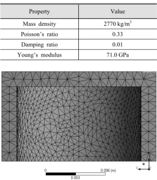
본 모델과 두께 조절 모델 및 결합부 변형 모델에 대해 진동 해석을 하였다. 유한요소 해석 프로그램인 ANSYS 를 사용하였다. 하우징의 재질은 알루미늄이고, 이 재 질의 물성치(12)를 Table 1에 기재하였다.
2.1 기본 모델
Fig. 2에 보인 초음파 센서 하우징을 기본 모델로 하였 다. 원판의 지름은 15.5 mm이고, 원통의 높이는 9.0 mm 이며, 이들의 두께는 1.5 mm이다. 사면체(SOLID76) 요 소로 구성한 유한요소 모델의 단면도를 Fig. 3에 보였 다. 요소의 크기는 0.5 mm 이하이며, 요소의 수는 약 16 000개이다.
경계조건과 가진조건이 적용되는 하우징의 모습을 Fig. 4에 보였다. 경계부는 그림의 B로서 원통의 플랜 지이고, 여기에 고정지지 조건을 설정하였다. 가진부 는 그림의 A로서 압전 소자가 부착되는 면이다. 이는 하우징 원판의 안쪽 면 중앙에 지름 6.5 mm인 원이다.
모드해석을 통해 고유진동 특성을 파악하였다. 1차와 2차 모드의 고유진동수는 각각 43.6 kHz와 44.6 kHz 로 나타났는데, 이들은 주로 원통의 진동이다. 원판의 두 께방향 진동은 3차 모드로서 고유진동수는 56.0 kHz 이고, 이 모드가 초음파 방사에 기여한다.
Fig. 1 Ultrasonic sensors on a bumper
Fig. 2 Cross-sectional view of an ultrasonic sensor
Property Value
Mass density 2770 kg/m3
Poisson’s ratio 0.33
Damping ratio 0.01
Young’s modulus 71.0 GPa
Table 1 Material properties of aluminum
Fig. 3 Sectional view of finite element model of the original housing
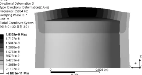
조화가진 응답 해석을 통해 하우징 원판의 두께 방 향 진동변위 분포를 구하였다. 가진부에 가진력 크기 1 N이고 진동수 56.0 kHz인 조화가진을 인가하였고, 해 석 결과를 Fig. 5에 제시하였다. 하우징 원판의 중심에 서 진동 변위가 가장 크고, 원판 둘레에 가까울수록 변 위가 작다. 이 기본 모델의 원판 중심 진동 변위 크기를 기준으로 변형 모델들의 진동 변위를 정규화한다.
2.2 두께 조절 모델
하우징 기본 모델에서 원판과 원통 벽의 두께를 점 차 감소시킴에 따른 진동 크기 변화를 파악하였다. 기 본 모델의 하우징 두께 1.5 mm를 기준으로 0.2 mm씩 감소시킨 모델에 대하여 진동 해석을 하였다. 모드해 석 결과에서 원판의 두께방향 진동 모드의 고유진동수 를 Fig. 6에 그래프로 나타내었다. 하우징의 원판과 원 통 벽이 얇을수록 고유진동수가 작다. 그 이유는 얇을 수록 판의 굽힘강성이 작고 플랜지 고정부 폭이 작아 좀 더 유연하기 때문으로 판단된다. 이 진동수를 조화 가진 해석의 가진 진동수로 선정하였다.
조화가진 응답 해석을 하여 결과를 Fig. 7에 두 가
지 그래프로 나타내었다. 기본 모델(두께 1.5 mm)에서 원판 중심의 진동변위 진폭을 기준으로 정규화하였다.
Fig. 7(a)는 원판 중심에서 두께방향 진동 변위가 하 우징 두께에 따라 변화하는 양상을 보여준다. 하우징 이 얇을수록 진동변위 진폭이 크다. 그 이유는, 고유진 동수에서와 같이, 얇을수록 판의 굽힘강성이 작고 플 랜지 고정부의 폭아 작아 좀 더 유연하기 때문으로 판 단된다.
Fig. 7(b)에는 원판 내에서 두께방향 진동변위 분포 를 하우징 두께별로 나타내었다. 진동변위가 원판 중심 에서 가장 크고 가장자리로 갈수록 작아지는 양상이 유 사하다. 하우징 전체 벽 두께를 감축하는 것은 센서 견 고성에 지장을 주어 실현성이 약하다. 그렇지만 Fig. 7 의 결과를 통해, 진동 원판의 둘레와 원통 벽의 결합부 의 변형에 의해서도 진동 크기가 달라질 수 있음을 예 상하게 되었다.
2.3 결합부 변형 모델
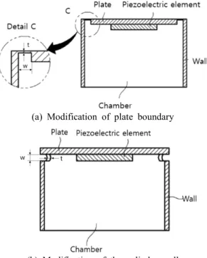
초음파 센서의 하우징이 Fig. 8에 보인 바와 같이 변형된 구조(8)에서 하우징 모델의 진동 해석을 하였다.
Fig. 8(a)의 하우징은 원판 부분에서 둘레가 얇다. Fig.
8(b)의 하우징은 원통 벽에서 원판과 연결되는 부분 이 얇다.
(1) 원판 둘레 변형 모델 (model 1)
Fig. 8(a)의 원판 둘레 변형 하우징을 모델링하여
Fig. 4 Housing model showing boundary B and exciting area A
Fig. 5 Vibration response in the original housing model
Fig. 6 Natural frequency of the plate thickness mode in the thickness-modified model
Fig. 9에 보였다. 이 변형 모델은 Fig. 9(a)에 보인 바 와 같이 원판 둘레에서 폭 w가 0.5 mm인 원환 부분에 두께 t가 1.5 mm보다 얇은 구조이다. 원판 둘레 변형부 두께는 Fig. 9(b)에 보이는 화살표의 길이 만큼이다.
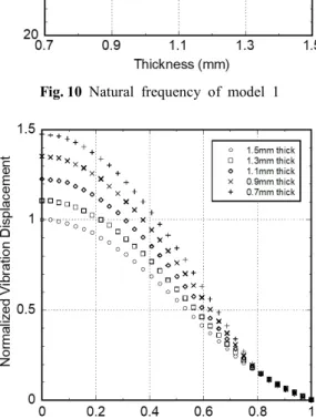
해석 모델의 경계부 및 가진부는 Fig. 4에 보인 기본 모델의 경우와 동일하다. 모드해석 결과에서 원판의 두 께방향 진동 모드의 고유진동수를 Fig. 10에 그래프로 나타내었다. 원판 둘레가 얇을수록 고유진동수가 작다.
그 이유는 앞 절의 두께 조절 모델에 대한 설명과 같다.
이 진동수에 대해서 조화가진 응답 해석을 하였다. 원
판 둘레 변형 모델의 두께방향 진동 분포를 정규화하 여 Fig. 11에 나타내었다. 5가지 원판 둘레 두께 변형 하우징 중 1.3 mm와 0.7 mm 모델의 해석 결과를 Fig. 12 에 보였다. 진동 변위 분포는 유사한 양상이고, 원판 둘레가 얇을수록 진동변위가 크다.
(a) At the center
(b) Distribution
Fig. 7 Vibration displacement in thickness direction at the thickness-modified model
(a) Modification of plate boundary
(b) Modification of the cylinder wall Fig. 8 Cross-sectional view of the modified housing
structure of an ultrasonic sensor
(a) housing with plate and cylinder
(b) Enlarged view of the plate boundary Fig. 9 Cross-sectional view of model 1 (plate boundary
modified)
(2) 원통 벽 결합부 변형 모델 (model 2)
Fig. 8(b)의 원통 벽 결합부 변형 하우징을 모델링하 여 Fig. 13에 보였다. 이 변형 모델은 Fig. 13(a)에 보인 바와 같이 원통 벽에서 결합부 쪽 폭이 0.5 mm인 부분 에 두께가 1.5 mm보다 얇은 구조이다. 원통 벽 결합부 두께는 Fig. 13(b)에 보이는 화살표의 길이 만큼이다.
해석 모델의 경계부 및 가진부는 Fig. 4에 보인 기본 모델의 경우와 동일하다. 모드해석 결과에서 원판의 두 께방향 진동 모드의 고유진동수를 Fig. 14에 그래프로 나타내었다. 원통 벽 결합부가 얇을수록 고유진동수가 작다. 그 이유는 앞 절에의 두께 조절 모델에 대한 설명
과 같다. 이 진동수를 가진 진동수로 설정하여 조화가진 응답 해석을 하였다. 원통 벽 결합부 변형 모델의 원판 두께방향 진동 분포를 정규화하여 Fig. 15에 나타내었 다. 5가지 변형 하우징 중 1.3 mm와 0.7 mm 모델의 해 석 결과를 Fig. 16에 보였다. 진동 변위 분포는 유사한 양상이고, 원통 벽 결합부가 얇을수록 진동변위가 크다.
Fig. 10 Natural frequency of model 1
Fig. 11 Vibration distribution of model 1
(a) Boundary thickness 1.3 mm
(b) Boundary thickness 0.7 mm
Fig. 12 Vibration response in model 1 (plate boundary deformed)
(a) Housing with plate and cylinder
(b) Enlarged view of cylinder wall
Fig. 13 Cross-sectional view of model 2 (cylinder wall modified)
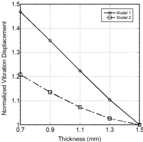
Fig. 11과 Fig. 15에 제시된 두 모델의 진동 변위 분 포 결과에서 원판 중심의 진동 변위 크기를 Fig. 17에 그래프로 나타내어 비교하였다. 두 가지 변형 하우징 모델 중 원통 벽 결합부 변형보다 원판 둘레 변형의 경 우가 진동 변위를 크게 하는 데에 유리한 것으로 나 타났다.
3. 음향 유한요소 해석
앞 절에서 구한 진동 변위 분포를 적용하여 센서의 하우징 구조에 따른 초음파의 음향 특성을 파악하고자
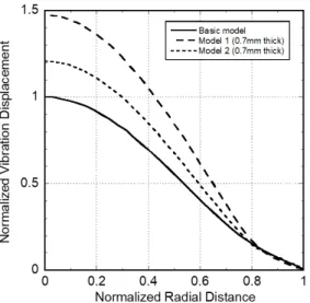
하였다. Fig. 11과 Fig. 15의 결과 중 기본 모델(두께 1.5 mm)과 두 가지 변형 모델의 진동 변위 분포를 Fig. 18에 함께 나타내었고, 이를 음향 가진조건으로 사용하였다.
음향 유한요소 해석을 위해, 센서로부터 방사하는 초
Fig. 14 Natural frequency of model 2
Fig. 15 Vibration distribution of axisymmetric housing control model
(a) Cylinder edge thickness 1.3 mm
(b) Cylinder edge thickness 0.7 mm
Fig. 16 Vibration response of model 2 (cylinder wall modified)
Fig. 17 Vibration displacement at the center of the plate of two housing models
음파가 전파하는 영역을 반 구 형상으로 설정하고 반 구의 축대칭 1/16 영역을 Fig. 19에 보인 바와 같이 음향 해석 모델로 삼았다. 요소 종류는 사면체(FULID 30)이며, 요소의 크기는 1 mm보다 작게 하여 파장 (6.07 mm)의 1/6 미만이고, 요소의 수는 약 835 000개 이다. Fig. 19(a)의 음향 해석 모델에서 네모 친 센서 부 근을 확대하여 Fig. 19(b)에 보였다. 아래면의 분포도 는 하우징 원판의 진동 변위로서, 둘레로 갈수록 진폭 이 작다.
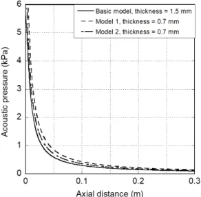
Fig. 19에 보인 음향해석 모델에 Fig. 18의 진동 변 위 분포를 가진조건으로 적용하여 음향 해석을 하였 다. 해석 결과 중 음압레벨(sound pressure level)을 Fig. 20에 나타내었다. 원판 중심의 축 방향 거리별 음 압을 Fig. 21에 나타내었다. 원판 변형 모델(model 1) 의 경우가 음압이 가장 크다. 원판 중심의 축 방향 거리 0.3 m에서 음압과 음압레벨을 Table 4에 기재하여 비 교하였다. 음압과 음압레벨이 원판 둘레 변형 모델의 경우에 가장 크다. 이는 Fig. 17과 Fig. 18에서 비교된 진동 변위 크기 경향과 일치한다.
추가하여, 지향성과의 연관성을 조사하였다. 방향각 에 따른 상대음압은 지향성 인자(directivity factor)라 고 하며(13), 음향 유한요소 해석 결과로부터 지향성 인 자 H(θ)를 산출하여 Fig. 22에 나타내었다. 배플(baffle) 된 음원에 의한 방사 음파의 지향성 인자와 지향성 D
Fig. 18 Vibration displacement in the plate of various housing structures
(a) 1/16 of hemisphere model
(b) Excitation portion
Fig. 19 Acoustic finite element analysis model
(a) Basic model (1.5 mm thick)
(b) Model 1 (0.7 mm thick)
(c) Model 2 (0.7 mm thick)
Fig. 20 Sound pressure level distribution of the ultra- sound radiating from the sensor
의 관계는 다음과 같다(13).
sin
(1)
여기서 분자의 4π는 단위 반지름 구의 표면적을 의미 하고, 분모의 θ 는 방향각을 의미한다. 적분 구간은 배 플된 반 무한공간이므로 0부터 π/2까지이다. 유한요소 해석 결과를 사용하기 위해 식 (1)을 이산화하면 다음 과 같다.
sin ∆
(2)
여기서 △θ는 요소 간격에서 발생하는 각도 변화량을 의미한다. 식 (2)를 사용하여 하우징 구조에 따른 지향 성을 산출하여 Table 2에 기재해서 비교하였다. 기본 모델과 원통 벽 변형 모델(model 2)이 원판 변형 모델 (model 1)보다 지향성이 크다. 각 모델의 정규화 진동 분포는 모두 유사함을 예측할 수 있고, 지향성은 그 차 이가 크지 않다. 즉, 원판 진동 변위를 크게 하여 방사 음압을 크게 하지만 이는 지향성과 직결되지는 않는 것으로 판단된다.
4. 결 론
초음파 센서의 측정거리 범위를 증대시키고자 하 우징 구조에 따른 진동 특성과 음향 특성을 파악하였 다. 축대칭 형상을 기본으로 하여 기본모델과 변형모 델에 대한 진동분포를 진동 유한요소 해석으로 구하 였다. 변형모델의 변형부 두께가 얇을수록 원판의 진 폭이 크다. 원판 둘레를 변형한 경우가 원통 벽을 변 형한 경우보다 진폭이 더 크다.
진동 유한요소 해석의 결과를 음향 유한요소 해석 에 적용하여 하우징 구조에 따른 음향 특성을 파악하 였다. 원판 둘레 변형 하우징의 경우가 거리별 음압과 음압레벨이 가장 컸다. 이는 진동 해석에서 진동변위 크기를 비교한 결과와 일치한다. 원판 둘레를 변형하 여 장거리용 초음파 센서의 최대 감지거리 향상 설계 에 반영할 수 있다.
References
(1) Kim, J. O., 2000, Sensors and Actuators Using Ultra- Acoustic
pressure at 0.3 m (Pa)
SPL at 0.3 m
(dB)
Directivity
Basic model 99.4 39.9 16.09
Model 1
(0.7 mm thick) 143.3 43.1 15.05
Model 2
(0.7 mm thick) 120.2 41.6 16.12
Table 2 Acoustic performances according to housing structures
Fig. 21 Acoustic pressure in the axial direction for various housing structures
Fig. 22 Directivity factor for various housing structures
sound, Transactions of the Korean Society for Noise and Vibration Engineering, Vol. 10, No. 5, pp. 723~728.
(2) Choi, H. and Jang, S. W., 2012, Front and Rear Vehicle Monitoring System Using Ultrasonic Sensors, Journal of the Korea Institute of Information and Com- munication Engineering, Vol. 16, No. 6, pp. 1125~1132.
(3) Kim, G. S., 2004, Perception of Small-obstacle Using Ultrasonic Sensors for a Mobile Robot, Proceedings of the KSPE Autumn Conference, pp. 97~100.
(4) Yoo, G. S., Lee, T. H. and Chae, M. K., 2017, Ultrasonic Transducer for Vehicle, Korea Patent 10-1,728,225.
(5) Dekker, D. L., Piziali, R. L. and Dong, E., 1974, Effect of Boundary Conditions on the Ultrasonic-beam Characteristics of Circular Disks, Journal of the Acoustical Society of America, Vol. 56, No. 1, pp. 87~93.
(6) Seon, S. O., Kim, J. O., Chae, M. K. and Yoo, G. S., 2018, Acoustic Characteristics Depending on the Vibration Distribution of Ultrasonic Sensors, Transactions of the Korean Society for Noise and Vibration Engineering, Vol. 28, No. 4, pp. 490~500.
(7) Shinji, A. and Junshi, O., 2001, Ultrasonic Sensor, United State Patent 6,250,162.
(8) Park, J. H., Yoo, G. S., Chae, M. K. and Yoon, J.
H., 2015, Ultrasonic Transducer for Long Distance, Korea Patent 10-1,491,462.
(9) Leissa, A. W., 1969, Vibration of Plates, National Aeronautics and Space Administration (NASA), Washington D.C., United States, pp. 97~100.
(10) Azimi, S., 1988, Free Vibration of Circular Plates with Elastic Edge Supports Using the Receptance Method, Journal of Sound and Vibration, Vol. 120, No. 1, pp. 19~35.
(11) Melnikov, Y. A., 2001, Green’s Function of a Thin
Circular Plate with Elastically Supported Edge, Journal of the Engineering Analysis with Boundary Elements, Vol.
25, No. 8, pp. 669~676.
(12) Dowling, N. E., 2013, Mechanical Behavior of Materials (4th ed.), Boston, Pearson, p. 49.
(13) Kinsler, L. E., 1999, Fundamentals of Acoustics, 4th ed., Wiley, New York, pp. 184~193.
Sang Ok Seon received the B.S. and M.S. degrees in mechanical engineer- ing from Soongsil University in 2016 and 2018, respectively. During his stay at Soongsil as a graduate stu- dent, he was working on ultrasonic sensors and wave propagation. Since July 2018 he has been working at LG Display, Co. Ltd.
Jin Oh Kim received the B.S. and M.S. degrees in mechanical engineer- ing from Seoul National University in 1981 and 1983, respectively, and the Ph.D. degree from University of Pennsylvania in 1989. For ten years he has got research experiences at Korea Research Institute of Standards and Science, North- western University, and Samsung Advanced Institute of Technology. Since 1997, he has been working at Soongsil University, where he is currently a Professor of mechan- ical engineering. His research interests are in the area of ultrasonic sensors and actuators using mechanical vi- brations and waves.