APPLICATION OF FINITE ELEMENT ANALYSIS TO EVALUATE PLATFORM SWITCHING
Yang-Soo Kim, D.D.S., M.S.D., Chang-Whe Kim, D.D.S., M.S.D., Ph.D., Kyung-Soo Jang, D.D.S., M.S.D., Ph.D., Young-Jun Lim, D.D.S., M.S.D., Ph.D.
Department of Prosthodontics, Graduate School, Seoul National University
Statement of problem. Platform switching in implant prosthesis has been used for esthet- ic and biological purpose. But there are few reports for this concept.
Purpose. The purpose of this study is evaluation of platform switching in wide implant by three dimensional finite element analysis.
Materials and Methods. The single implant and prosthesis was modeled in accordance with the geometric designs for Osstem implant system. Three-dimensional finite element mod- els were developed for (1) a wide diameter 3i type titanium implant 5 mm in diameter, 13 mm in length with wide cemented abutment, titanium alloy abutment screw, and prosthesis (2) a wide diameter 3i type titanium implant 5 mm in diameter, 13 mm in length with regular cemented abut- ment, titanium alloy abutment screw and prosthesis(platform switching) was made for finite ele- ment analysis. The abutment screws were subjected to a tightening torque of 30 Ncm. The amount of preload was hypothesized to 650 N, and round and flat type prostheses were loaded to 200 N.
Four loading offset point (0, 2, 4, 6 mm from the center of the implants) were evaluated. Models were processed by the software programs HyperMesh and ANSA. The PAM-CRASH 2G sim- ulation software was used for analysis of stress. The PAM-VIEW and HyperView were used for post processing.
Results. The results from experiment were as follows;
1. von Mises stress value is increased in order of bone, abutment, implant and abutment screw.
2. von Mises stress of abutment screw is lower when platform switching.
3. von Mises stress of implant is lower when platform switching until loading offset 4 mm.
4. von Mises stress of abutment is similar between each other.
5. von Mises stress of bone is slightly higher when platform switching.
Conclusion. The von Mises stress pattern of implant components is favor when platform switch- ing but slightly higher in bone stress distribution than use of wide abutment. The research about stress distribution is essential for investigation of the cortical bone loss.
Key Words
Finite element analysis, Platform switching, Implant, Microgap, Cortical bone resorption J Korean Acad Prosthodont : Volume 43, Number 6, 2005
D
ifferent from Branemark implant system, 3i wide implant have the same external hex as standard implant. Therefore 3i wide implant would be able to make prosthesis with standard size abutment, then location of microgap could be changed.The location of the microgap as well as rough/smooth implant interface have a significant effect on marginal bone formation.1-4Bone remod- eling occurs rapidly during the early healing phase after abutment connection for submerged implants.1
Crestal bone changes around two-piece, sub- merged titanium implants are significantly influ- enced by possible movements between implants and abutments, but not by the size of the micro- gap(interface). Thus, significant crestal bone loss occurs in two-piece implant configurations even with the smallest-sized microgaps (< 10 microns) in combination with possible movements between implant components.2-4The absence of micro- gap at the bone crest was associated with reduced peri-implant inflammatory cell accumulation and minimal bone loss.4
Gingival esthetics around natural teeth is based upon a constant vertical dimension of healthy peri- odontal soft tissues, the biologic width.2The bio- logic width is consisted of an epithelial and a supracrestal connective tissue barrier. The junc- tional epithelium established the attachment to the implant surface, whereas the collagen fibers and fibroblasts of the connective tissue seal were ori- ented parallel to the implant.5The dimension, from the crown-implant interface to the first bone-to-implant contact, is consistent with the for- mation of a biologic width similar to that found around the natural dentition.6
Surgical trauma, occlusal overload, peri-implan- titis, and implant crest module is also hypothesized
loss following abutment connection has both horizontal and vertical components. The horizontal component consists of the 1.3 mm to 1.4 mm of bone loss from the microgap to the crest of bone.8 If the horizontal component can be controlled or decreased, then crestal bone loss can also be decreased. Platform switching is a simple and effective way to control circumferential bone loss around dental implants. By altering the hor- izontal position of the microgap, the horizontal component of bone loss after abutment connec- tion can be reduced. Instead of using an abutment that was 5 mm in width, a standard abutment was used that measured 4.1 mm. This results in a microgap that is 0.45 mm from the edge of the plat- form. Consequently, the horizontal component of bone loss from the microgap was reduced, and osseous dimensions were maintained.9
From clinical point of view prosthesis with platform switching has been used for esthetic and biological purpose. But there are few reports for this concept. There is not yet clinically approved data about bone loss and mechanical sta- bility by platform switching.
The purpose of this study is evaluation of change of stress distribution about implant com- ponents and bone due to horizontal migration of microgap by platform switching and change of mechanical stability by finite element analysis.
MATERIALS AND METHODS
The single implant and prosthesis was modeled in accordance with the geometric designs for Osstem implant system(Osstem Co., Korea).
Three-dimensional finite element models were developed for (1) a wide diameter 3i type titani- um implant 5 mm in diameter, 13 mm in length with wide cemented abutment, titanium alloy abut- ment screw, and prosthesis (2) a wide diameter 3i
Table I. The nodes and elements for finite element analysis
Model Name Crown Abutment Abutment screw Implant Cortical bone Trabecular bone TOTAL Implant node element node element node element node element node element node element node element original 6289 5472 5472 4128 11384 56361 27817 136313 6419 10902 25644 81124 74639 228339 platform
7968 6912 7776 6336 11384 56361 27817 136313 6419 10902 25644 81124 78670 297948 switching
Table II. Poisson’s ratio, elastic modulus, bulk modulus, shear modulus
Bulk modulus(GPa) Shear modulus (GPa) Young’s modulus(GPa) Poisson’s ratio
Titanium 87.50 40.38 105.0 0.30
Cortical bone 11.67 5.38 14.0 0.30
Trabecular bone 5.0 0.52 1.5 0.45
a) b) c)
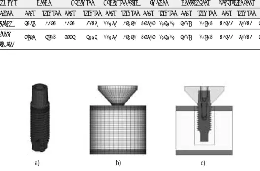
Fig. 1.The finite element model with standard abutment.
a) mesh of the abutment and the implant b) overall model embedded in bone c) cross sectional view
a) b) c)
Fig. 2.The finite element model with wide abutment.
a) mesh of the abutment and the implant b) overall model c) cross sectional view
in length with regular cemented abutment, tita- nium alloy abutment screw and prosthesis(plat- form switching) was made for finite element analysis. The nodes and element for model is showed at table I.
Poisson’s ratio and elastic modulus is marked at table II. Prosthesis was illustrated Fig. 1 and 2.
Modeling were processed by the software pro- grams HyperMesh version 7.0(Altair engineering Inc., Troy, MI, U.S.A.) and ANSA(beta CAE Systems, version 11.2.4.). All materials used in the models were considered to be isotropic, homoge- nous, and linearly elastic. The abutment screws were subjected to a tightening torque in 30 Ncm.
The preload amount was hypothesized 650 N. Real clinical value of the preload have a high standard deviation. According to the study by Martin et al10, titanium alloy abutment screw have preload from 434.8+/-310.6 N to 636.1+/-336.6 N at 32 Ncm torque tightening. It is difficult for standardiza- tion of preload, so we use Lisa’s experimental val- ue for preload by finite element analysis. When friction coefficient is 0.12, preload value of Unigrip screw and TorqueTite screw is approximately 650 N at 30 Ncm.11For real stress distribution by preload, we rotate abutment screw without con- tact condition then apply contact condition for stress distribution by preload. Implant prosthe- sis was vertically loaded by 200 N. 4 loading
offset point (0, 2, 4, 6 mm from center of implant) was evaluated. 12 mm diameter, 9 mm height round and flat occlusal table prosthesis was loaded to 200 N vertically(Fig. 1, 2). Bending moment is generated by loading offset. The PAM-CRASH 2G (ESI group, version 2004, France) was used for analysis of stress. The PAM- VIEW(ESI, version 2004, France)and HYPER- VIEW(Altair engineering Inc., Troy, MI, USA) were used for post processing.
RESULTS
When application of tightening torque for pre- load, the von Mises stress is concentrated at the first thread of cortical bone. In center loading, the von Mises stress is distributed broadly at the first thread of bone. With increasing loading offset, the von Mises stress is increased at cortical bone which is influenced by compression. The stress with platform switching is higher than the other. Total amount of stress concentrated at bone is small than other component of implant(Fig.
3 to 5).
The stress is increased in order of abutment, implant, abutment screw(Fig. 8). Irrespective of loading offset, the stress pattern by preload is main- tained(Fig. 6, 7).
The von Mises stress of platform switching
a) b) c) d) e)
implant is small than original until loading offset 4 mm(Fig. 9). The stress pattern by offset loading is well distributed in the model with platform
switching than the other.
The stress of the abutment screw is decreased as increasing of loading offset. The von Mises stress
a) b) c) d) e)
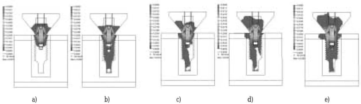
Fig. 4.The von Mises stress pattern of bone without platform switching.
a) stress distribution after preload b) 200 N center loading c) 2 mm offset loading d) 4 mm offset loading e) 6 mm offset loading
a) b) c) d) e)
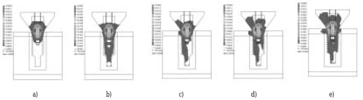
Fig. 6.The von Mises stress pattern with platform switching.
a) stress distribution after preload b) 200 N center loading c) 2 mm offset loading d) 4 mm offset loading e) 6 mm offset loading
Fig. 5.The von Mises stress of bone with and without platform switching.
of the abutment screw with platform switching is between each other. Preload is maintained until
a) b) c) d) e)
Fig. 7.The von Mises stress pattern without platform switching.
a) stress distribution after preload b) 200 N center loading c) 2 mm offset loading d) 4 mm offset loading e) 6 mm offset loading
Fig. 8.The von Mises stress of the implant components. Fig. 9.The von Mises stress of the implant with and with- out platform switching.
Fig. 10.The von Mises stress of the abutment screw with and without platform switching.
Fig. 11.The von Mises stress of the abutment with and without platform switching.
The von Mises stress
DISCUSSION
Load transfer from implants to surrounding bone depends on the type of loading, the bone- implant interface, the length and diameter of the implants, the shape and characteristics of the implant surface, the prosthesis type, and the quantity and quality of the surrounding bone.12The objective of platform switching is to reduce the cre- stal bone loss by horizontal migration of micro- gap. By reducing the crestal bone loss, we utilize full length of short wide implant and minimize the change of embrasure shape. Among the factors pro- posed as the possible causes for bone resorp- tion were surgical trauma or stress during implant tightening and inadequate loading in the first year after abutment connection.13Other factors pro- posed to be related to bone loss are the biologic width around implants1, and implant surface treatment.14Retention elements at the implant neck will counteract marginal bone resorption in accordance with Wolff’s law.15 Cortical bone loss can be reduced by retention element (microthread) or rough surface treatment. Distance between platform and first thread is clinically important because of bone loss, Branemark wide implant system is 1.2 mm distance but 3i wide implant system is 0.4~1.0 mm from platform.
Bone loss to the starting point of first thread need more research.
When application of tightening torque for pre- load, the von Mises stress is concentrated at the first thread of cortical bone. With a ‘flat to flat’
implant-abutment interface at the level of the bone-connective tissue junction, the peak bone- implant interface shear stress was located at the very top of the marginal bone.16 When center loading, the von Mises stress is distributed broadly at the first thread of bone. With increas- ing loading offset, the von Mises stress is increased at cortical bone which is influenced by com-
pression. The stress of bone when platform switching is slightly higher than the other(Fig. 5).
Stress fracture of bone is believed to result from accumulation and coalesence of microdamage occuring when bone remodeling is insufficient to mend the microdamage as it is formed. Overload can cause bone resorption or fatigue failure of the implant, whereas underloading of the bone may lead to disuse atrophy and subsequent bone loss.15,17The crestal bone region is of particular interest because of the observations of progressive bone resorption(saucerization). On the basis of both histologic examination and FEA results, an equiv- alent stress of 1.6 MPa has been deemed sufficient to avoid crestal bone loss from disuse atrophy in the canine mandibular premolar region.18Total amount of stress concentrated at bone is small than other component of implant. Whether or not decreasing of cortical bone resorption by slight- ly high stress with platform switching need fur- ther research.
The stress is increased in order of abutment, implant, abutment screw(Fig. 8). Clinical uti- lization of grade 5 titanium, titanium alloy for abut- ment screw, grade 4 titanium for implant, grade 3 titanium for abutment may be related for com- pensation of the von Mises stress. The von Mises stress of abutment is similar between each oth- er(Fig. 10). And von Mises stress is maintained until loading offset 2 mm. Irrespective of loading off- set, the stress pattern by preload is maintained.
Preload could maintain the union of implant components, and resist the external load from mas- tication. Optimum preload is within the mater- ial elastic range of the abutment screw. When the optimum preload is achieved, the abutment screw experiences the entire external load applied to the clamped parts. At this point, the screw joint is said to be protected against external force applications as long as these external loads do not exceed the preload. Thus, the accuracy of the
preload reached during screw tightening and clamping of the abutment and the implant togeth- er becomes a major and critical subject for study- ing the dynamic loading of the implant com- plex.19
The von Mises stress of platform switching implant is small than original until loading offset 4 mm, but well distributed through entire implant (Fig. 6). The stress of abutment screw is decreased as increasing of loading offset(Fig. 10). The von Mises stress of abutment screw with platform switching is small than original. The phenomenon that the amount of stress is decreased with increase of loading offset may be due to bending moment. With increase of loading offset, bending moment is also increased. There are two way of loading path, one way is in order of prosthesis, abutment, abutment screw and implant and the other way is prosthesis, abutment and platform of implant. With increase of bending moment, main way of stress transfer is the latter, so the stress of abutment screw is decreased. This means that the amount of bending moment is determinant fac- tor of stress distribution.
CONCLUSIONS
Within the limitation of this study, the follow- ing conclusion could be drawn.
1. von Mises stress value is increased in order of bone, abutment, implant and abutment screw.
2. von Mises stress of the abutment screw is lower when platform switching.
3. von Mises stress of the implant is lower when platform switching until loading offset 4 mm.
4. von Mises stress of the abutment is similar between each other.
5. von Mises stress of the bone is slightly higher when platform switching.
The von Mises stress pattern of implant com-
slightly higher in bone stress distribution than with- out platform switching. Stress research about patients is essential for investigation of the cortical bone loss.
REFERENCES
1. Hermann JS, Cochran DL, Nummikoski PV, Buser D. Crestal bone changes around titanium im- plants. A radiographic evaluation of unloaded nonsubmerged and submerged implants in the ca- nine mandible. J Periodontol 1997;68:1117-1130.
2. Hermann JS, Buser, D, Schenk RK, Schoolfield JD, Cochran DL. Biologic width around one- and two-piece titanium implants. Clin Oral Implants Res 2001;12:559-571.
3. Hermann JS, Schoolfield JD, Schenk Rk, Buser D, Cochran DL. Influence of the size of the microgap on crestal bone changes around titanium im- plants. A histometric evaluation of unloaded non- submerged implants in the canine mandible. J Periodontol 2001;72:1372-1383.
4. Broggini N, McManus LM, Hermann JS, Medina RU, Oates TW, Shenk RK, Buser D, Mellonig JT, Cochran DL. Persistent acute inflammation at the implant-abutment interface. J Dent Res 2003;82:
232-237.
5. Glauser R, Schupbach P, Gottlow J, Hammerle CH. Periimplant soft tissue barrier at experimen- tal one-piece mini-implants with different sur- face topography in humans: A light-microscopic overview and histometric analysis. Clin Implant Dent Relat Res 2005:7:s44~51.
6. Harman GA, Cochran DL. Initial implant position determines the mafnitude of crestal bone remod- eling. J Periodontol 2004;75:572-577.
7. Oh TJ, Yoon J. Misch CE, Wang HL. The causes of early implant bone loss:myth or science? J Periodontol 2002;73:322-333.
8. Tarnow DP, Cho SC, Wallace SS. The effect of inter-implant distance on the height of inter-implant bone crest. J Periodontol 2000;71:546-549.
9. David M Gardner. Platform switching as a means to achieving implant esthetics. N Y State Dent J 2005;71:34-38.
10. Martin WC, Woody RD, Miller BH, Miller AW.
Implant abutment screw rotations and preloads for four different screw materials and surfaces. J Prosthet Dent 2001;86:24-32.
11. Lang LA, Kang B, Wang RF, Lang BR. Finite ele- ment analysis to determine implant preload. J Prosthet Dent 2003;90:539-546.
12. Geng JP, Tan KB, Liu GR. Application of finite el- ement analysis in implant dentistry: A review of
13. Adell R, Lekholm U, Rockler B, Branemark PI, A 15 year study of osseointegrated implants in the treatment of the edentulous jaw. Int J Oral Surg 1981;10:387-416.
14. Pilliar RM, Deporter DA, Watson PA, Valiquette N. Dental implant design-effect on bone remodeling.
J Biomed Mater Res 1991;25:467-83.
15. Hansson S. The implant neck: smooth or provid- ed with retention elements. A biomechanical ap- proach. Clin Oral Implants Res 1999;10:394-405.
16. Hansson S. A conical implant-abutment interface at the level of the marginal bone improves the distribution of stresses in the supporting bone An axisymmetric finite element analysis. Clin Oral Implants Res 2003;14;286-293.
17. Wiskott HW, Belser UC. Lack of integration of smooth titanium surface: a working hypothesis based on strains generated in the surrounding
bone Clin Oral Implants Res 1999;10:429-444.
18. Vaillancourt H, Pillar RM, McCammond D. Factors affecting crestal bone loss with dental implants par- tially covered with a porous coating: a finite element analysis. Int J Oral Maxillofac Implants 1996;11:351- 359.
19. Patterson EA, Johns RB. Theoretical analysis of the fatigue life of fixture screws in osseointegrated den- tal implants. Int J Oral Maxillofac Implants 1992;7:26-33.
Reprint request to:
CHANG-WHEKIM, D.D.S., M.S.D.,Ph.D.
DEPARTMENT OF PROSTHODONTICS, GRADUATESCHOOL, SEOULNATIONALUNIVERSITY
28-1 YEONGUN-DONG,CHONGNO-GU,SEOUL, 110-768, KOREA [email protected]