Introduction
Implant therapy is a common dental treatment in mo- dern dentistry and has become increasingly popular in the past two decades.1The quality and quantity of the alveo-
lar bone play an important role in treatment planning, sel- ection of the diameter and length of dental implants, and the treatment success rate.2 Cone-beam computed tomo- graphy (CBCT) is a relatively new and unique imaging technique for the maxillofacial region that enables three- dimensional (3D) analyses of the soft and hard tissue.3-6
Linear measurements are routinely used to determine the thickness and the height of the alveolar ridge as part of the presurgical assessment for implant therapy, measure the distance between anatomical landmarks in ortho- dontics, and estimate the size of pathologic lesions of the
Accuracy of linear measurement using cone-beam computed tomography at different reconstruction angles
Sima Nikneshan1, Shadi Hamidi Aval1, Neema Bakhshalian2, Shahriyar Shahab3, Mahdis Mohammadpour4, Soodeh Sarikhani5,*
1Department of Dental and Maxillofacial Radiology, School of Dentistry, Shahid Beheshti University of Medical Sciences, Tehran, Iran
2Department of Advanced Periodontology, School of Dentistry, University of Southern California, Los Angeles, USA
3Department of Dental and Maxillofacial Radiology, School of Dentistry, Shahed University of Medical Sciences, Tehran, Iran
4Department of Dental and Maxillofacial Radiology, School of Dentistry, Qazvin University of Medical Sciences, Qazvin, Iran
5Department of Dental and Maxillofacial Radiology, School of Dentistry, Golestan University of Medical Sciences, Golestan, Iran
ABSTRACT
Purpose: This study was performed to evaluate the effect of changing the orientation of a reconstructed image on the accuracy of linear measurements using cone-beam computed tomography (CBCT).
Materials and Methods: Forty-two titanium pins were inserted in seven dry sheep mandibles. The length of these pins was measured using a digital caliper with readability of 0.01 mm. Mandibles were radiographed using a CBCT device. When the CBCT images were reconstructed, the orientation of slices was adjusted to parallel (i.e., 0�), ++10�,
+
+12�, -12�, and -10�with respect to the occlusal plane. The length of the pins was measured by three radio- logists, and the accuracy of these measurements was reported using descriptive statistics and one-way analysis of variance (ANOVA); p⁄0.05 was considered statistically significant.
Results: The differences in radiographic measurements ranged from -0.64 to ++0.06 at the orientation of -12�, -0.66 to -0.11 at -10�, -0.51 to ++0.19 at 0�, -0.64 to ++0.08 at ++10�, and -0.64 to ++0.1 at ++12�. The mean absolute values of the errors were greater at negative orientations than at the parallel position or at positive orientations. The ob- servers underestimated most of the variables by 0.5-0.1 mm (83.6%). In the second set of observations, the re- producibility at all orientations was greater than 0.9.
Conclusion: Changing the slice orientation in the range of -12�to ++12�reduced the accuracy of linear mea- surements obtained using CBCT. However, the error value was smaller than 0.5 mm and was, therefore, clinically acceptable. (Imaging Sci Dent 2014; 44: 257-62)
KEY WORDS: Cone-Beam Computed Tomography; Dental Implants; Dimensional Measurement Accuracy
*The study was supported by the School of Dentistry, Shahid Beheshti University of Medical Science, Tehran, Iran (Grant No. 8856).
Received November 28, 2013; Revised July 16, 2014; Accepted August 12, 2014
*Correspondence to : Prof. Soodeh Sarikhani
Department of Oral and Maxillofacial Radiology, School of Dentistry, University of Golestan, Naharkhoran Blvd, Gorgan 49178, Iran
Tel) 98-171-5550700, Fax) 98-171-4422860, E-mail) e_soodeh@yahoo.com
Copyright ⓒ 2014 by Korean Academy of Oral and Maxillofacial Radiology
This is an Open Access article distributed under the terms of the Creative Commons Attribution Non-Commercial License (http://creativecommons.org/licenses/by-nc/3.0) which permits unrestricted non-commercial use, distribution, and reproduction in any medium, provided the original work is properly cited.
Imaging Science in Dentistry∙pISSN 2233-7822 eISSN 2233-7830
jaws.7,8Since CBCT images require image reconstruc- tion, any type of error in the reconstruction process, parti- cularly in the selection of the orientation of the recons- tructed image, may result in a change and an inaccuracy in the linear measurements conducted using CBCT. Image slice orientation, thickness, and interslice interval are often determined by the operator (task-specific imaging);
therefore, it is critical to achieve a standard image recon- struction orientation protocol to increase the diagnostic value of the system.8
The present study evaluates the effect of changing the orientation of the reconstructed CBCT image on the accu- racy of linear measurements and preoperative assessments for implant therapy.
Materials and Methods
This study was an assessment of diagnostic accuracy. A total of 42 prefabricated titanium pins of similar length were inserted in seven dry sheep mandibles (Fig. 1). The length of these pins was measured before their insertion in the mandibles by using a digital caliper (Mitutoyo Corp.,
Kawasaki, Japan) with readability of 0.01 mm (Fig. 2). To simulate soft tissue, mandibles were immersed in a water container and radiographed with NewTom VGi® (QR s.r.l., Verona, Italy). Imaging was carried out at a high-reso- lution field of view of 8 cm×12 cm with a voxel size of 0.125 mm and tube voltage of 120 kVp.
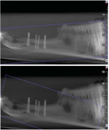
For the reconstruction of images by NNT viewer soft- ware (QR s.r.l., Verona, Italy), the orientation of slices was adjusted to parallel (i.e., 0�), ++10�, ++12�, -12�, and -10�with respect to the occlusal plane (Fig. 3). These intervals were chosen on the basis of a pilot study on the primary reconstruction of CBCT images conducted by the oral and maxillofacial radiology residents and faculty of our institution; each of these researchers had at least four years of experience with CBCT. This pilot study showed that the range of errors in angulation during image recon- struction was from -12�to ++12�, and hence, five differ- ent angles within this range were chosen to evaluate the effect of the angulation error on the measurement out- comes. The images were viewed on a 20-inch Philips mo- nitor (200P, Philips, Guildford, England) with a pixel resolution of 1024×1280 and color depth of 32 bits. Linear measurements of the lengths of pins were made by three oral and maxillofacial radiologists (Fig. 4). The observers
Fig. 1.Titanium pins are inserted in a dried sheep mandible.
Fig. 2.A digital caliper is used to measure the length of the pins prior to insertion in the mandible.
Fig. 3.Scout views show the scans with the reconstruction angle parallel (i.e., at 0�) and at 10�to the occlusal plane.
were allowed to control the contrast, sharpness, and bright- ness of the images as well as the slice thickness and the interslice interval as desired. Each observer measured each length twice with a two-week interval between the mea- surements. The accuracy of linear measurements obtained by CBCT was reported using descriptive statistics and one- way analysis of variance (ANOVA); p⁄0.05 was consi- dered statistically significant. Moreover, for the calcula- tion of the inter-rater reliability accuracy in this study, a weighted kappa statistical analysis was used.
Results
The difference in radiographic measurements made by the observers ranged from -0.64 to ++0.06 at the ori- entation of -12�, -0.66 to -0.11 at -10�, -0.51 to
+
+0.19 at 0�, -0.64 to ++0.08 at ++10�, and -0.64 to ++0.1 at ++12�(Fig. 5). Table 1 demonstrates the mean and standard deviation of the differences in measurements at each orientation considered and for each observer bet- ween the first and the second observations. The maxi- mum and minimum mean absolute values of the error were 0.34 and 0.20 at the orientation of -12�, 0.37 and 0.27 at -10�, 0.18 and 0.14 at 0�, 0.31 and 0.23 at ++10�, and 0.31 and 0.29 at ++12�, respectively. The results show- ed that the mean absolute value of the error was greater at negative orientations than at the parallel position or at positive orientations of the slices with respect to the occlu- sal plane. The maximum mean absolute value of the error was 0.37±0.13 observed at the orientation of -10�, where- as the minimum mean absolute value of the error was 0.14±0.87 recorded at 0�. The observers underestimated the length of the pins at most of the orientations by 0.5 to 0.1 mm (83.6%). In the second set of observations, taking into account the accuracy subgroups (error range), the reproducibility at all orientations was greater than 0.9.
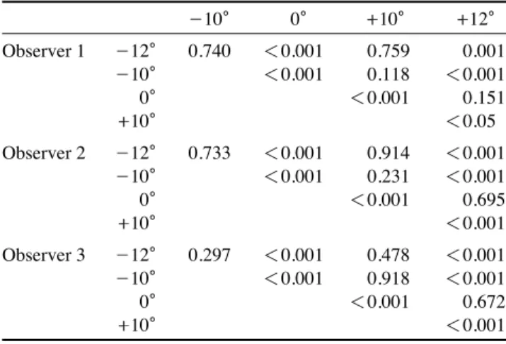
Table 2 shows the p value for the different orientation angles obtained using one-way ANOVA.
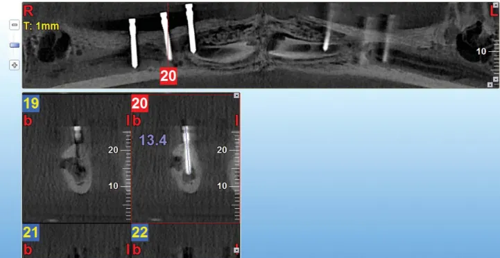
Fig. 4.Linear measurements are performed using the cross-sectional images of the pins.
Fig. 5.The graph shows the range of differences in measurements performed by three observers for the different angles used to re- construct the images.
Range of the differences in measurements(mm)
0.2
0
-0.2
-0.4
-0.6
-0.8
-12� -10� 0� 10� 12�
Discussion
The results of the present study revealed that by chang- ing the slice orientation within the range of -12�to ++12�
with respect to the occlusal plane during image reconstruc- tion, the accuracy of linear measurements using CBCT de- creases; nevertheless, these measurements can still be con- sidered highly accurate. In this study, titanium pins were used since titanium has a low atomic number and hence, will cause very small metal artifacts.9,10Furthermore, the observers were allowed to change and adjust the contrast, sharpness, and gamma factor (which is among the features of the NNT viewer software) of the images, and by doing so, they could further minimize the metal artifacts.
The highest mean difference between measurements in this study was observed at the orientation of -10�, while the lowest mean difference was recorded at 0�, which im- plies that during image reconstruction, adjusting the slice orientation to be parallel to the occlusal plane results in reducing the error in the linear measurements.
The mean absolute error value at negative orientations was greater than at the parallel position or at positive ori- entations with respect to the occlusal plane. The maximum mean of the absolute value of the error was observed at the orientation of -10�, while the minimum mean abso- lute value of the error was recorded at 0�. However, the differences in the mean errors of measurements between the considered orientations (-12�, -10�, 0�, 10�, and 12�) and the gold standard was less than 1 mm. In 2011, Gan- guly et al11demonstrated that the acceptable measurement error for implant placement was less than 1 mm. Therefore, in our study, the accuracy of measurements at all orienta- tions was considered clinically acceptable.
In a study by Sheikhi et al,12the accuracy of linear mea- surements was compared at normal and at different head positions in a Galileos CBCT system. In their study, dis- tances specified with radiopaque markers on the scans obtained at different head positions were measured. The mean difference between the physical (actual) and the radio- graphic measurements was found to be 0.45±0.05 mm.
Tomasi et al13evaluated the reliability and the reproduci- bility of linear measurements in the mandible by using CBCT at two different orientations of 0�and 45�. The mean
Table 1. The mean and standard deviation of the differences in measurements at each orientation considered and for each observer between the first and the second observations
Observer 1 Observer 2 Observer 3
First Second First Second First Second
observation observation observation observation observation observation
-12� Min -0.64 -0.64 -0.64 -0.52 -0.62 -0.43
Max -0.01 -0.06 -0.03 0.00 -0.13 -0.01
Mean -0.33±0.15 -0.24±0.14 -0.33±0.14 -0.22±0.11 -0.34±0.12 -0.20±0.10
-10� Min -0.66 -0.64 -0.66 -0.61 -0.56 -0.46
Max -0.14 -0.12 -0.11 -0.11 0.14 -0.11
Mean -0.37±0.13 -0.29±0.10 -0.36±0.12 -0.30±0.12 -0.03±0.08 -0.27±0.08
0� Min -0.51 -0.50 -0.41 -0.36 -0.32 -0.42
Max 0.19 0.19 0.09 0.09 0.09 0.09
Mean -0.12±0.12 -0.16±0.15 -0.12±0.12 -0.15±0.12 -0.13±0.10 -0.16±0.13
+
+10� Min -0.62 -0.64 -0.64 -0.44 -0.56 -0.43
Max 0.04 -0.01 0.08 -0.02 -0.02 -0.11
Mean -0.30±0.15 -0.25±0.14 -0.30±0.17 -0.23±0.10 -0.30±0.12 -0.27±0.08
+
+12� Min -0.64 -0.64 -0.42 -0.43 -0.44 -0.46
Max 0.06 0.09 0.06 0.10 0.00 -0.02
Mean -0.21±0.14 -0.24±0.13 -0.19±0.09 -0.22±0.11 -0.17±0.10 -0.22±0.09
Table 2.The p values between the measurements from the orien- tation angles for each observer
-10� 0� ++10� ++12�
Observer 1 -12� 0.740 ⁄0.001 0.759 0.001
-10� ⁄0.001 0.118 ⁄0.001
0� ⁄0.001 0.151
+
+10� ⁄0.05
Observer 2 -12� 0.733 ⁄0.001 0.914 ⁄0.001
-10� ⁄0.001 0.231 ⁄0.001
0� ⁄0.001 0.695
+
+10� ⁄0.001
Observer 3 -12� 0.297 ⁄0.001 0.478 ⁄0.001
-10� ⁄0.001 0.918 ⁄0.001
0� ⁄0.001 0.672
+
+10� ⁄0.001
absolute error value was 0.4 mm, which is almost to the same as the values obtained in our study. Further, Fakhar and Abbaszadeh14 evaluated the effects of changing the mandibular plane orientation on the accuracy of the linear dimensions of the tomographic images. Analyses showed statistically significant differences between measurements made at the standard position and upon the upward tilt of the mandibular plane. In general, in most cases, the mean absolute error value was 1 mm or less, which is within the acceptable range. However, a downward tilt of the mandi- ble caused a greater change in measurements than an up- ward tilt.
Hassan et al15evaluated the accuracy of linear measure- ments performed using 3D CBCT images at two different head positions. The greatest difference in measurements observed between the 3D models and the gold standard was less than 0.5 mm, and no significant difference was found between the linear measurements at the different head positions. Moshiri et al16compared the accuracy of linear measurements conducted using CBCT and conven- tional cephalograms and demonstrated that measurements using CBCT images had a higher accuracy than those using conventional lateral cephalograms. Further, they showed that the head position had no significant effects on the accuracy of linear measurements using CBCT.
Ludlow et al17in their study on the NewTom 9000 ma- chine revealed that the accuracy of linear measurements using CBCT was not significantly influenced by the vari- ations in the head orientation while the image was being acquired.
Moshfeghi et al18 evaluated the linear measurement accuracy of CBCT using NewTom VG on 22 anatomic landmarks in four dry skulls. Fifteen linear measurements were obtained using a digital caliper. The skulls were scanned at two settings: (a) voxel size of 0.3 mm and (b) voxel size of 0.15 mm. Radiographic distance measure- ments were made using the NNT viewer software in the axial and coronal sections by three observers. A statistical analysis showed high inter- and intra-observer reliability.
In conclusion, changing the slice orientation in the range of -12�to ++12�reduced the accuracy of linear measure- ments obtained using CBCT. However, the error values were smaller than 0.5 mm and were, therefore, clinically acceptable.
Acknowledgments
This manuscript has been entirely drawn up from a Master’s thesis, which was successfully completed by Dr.
Sarikhani under the supervision of Dr. Nikneshan.
References
1. Torres MG, Campos PS, Segundo NP, Navarro M, Crusoé- Rebello I. Accuracy of linear measurements in cone beam computed tomography with different voxel sizes. Implant Dent 2012; 21: 150-5.
2. Cavalcanti MG, Rocha SS, Vannier MW. Craniofacial mea- surements based on 3D-CT volume rendering: implications for clinical applications. Dentomaxillofac Radiol 2004; 33:
170-6.
3. Ziegler CM, Woertche R, Brief J, Hassfeld S. Clinical indica- tions for digital volume tomography in oral and maxillofacial surgery. Dentomaxillofac Radiol 2002; 31: 126-30.
4. Guerrero ME, Jacobs R, Loubele M, Schutyser F, Suetens P, van Steenberghe D. State-of-the-art on cone beam CT imag- ing for preoperative planning of implant placement. Clin Oral Investig 2006; 10: 1-7.
5. Kau CH, Richmond S, Palomo JM, Hans MG. Three-dimen- sional cone beam computerized tomography in orthodontics. J Orthod 2005; 32: 282-93.
6. Yamamoto K, Ueno K, Seo K, Shinohara D. Development of dento-maxillofacial cone beam X-ray computed tomography system. Orthod Craniofac Res 2003; 6 Suppl 1: 160-2.
7. Scarfe WC, Farman AG, Sukovic P. Clinical applications of cone-beam computed tomography in dental practice. J Can Dent Assoc 2006; 72: 75-80.
8. Kumar V, Ludlow JB, Mol A, Cevidanes L. Comparison of conventional and cone beam CT synthesized cephalograms.
Dentomaxillofac Radiol 2007; 36: 263-9.
9. Li T, MacDonald D. Osseo integrated implants. In: MacDo- nald D. Oral and maxillofacial radiology: a diagnostic approach.
Chichester: Wiley-Blackwell; 2011. p. 296-8.
10. Boas FE, Fleischmann D. CT artifact: cause and reduction techniques. Imaging Med 2012; 4: 229-40.
11. Ganguly R, Ruprecht A, Vincent S, Hellstein J, Timmons S, Qian F. Accuracy of linear measurement in the Galileos cone beam computed tomography under simulated clinical condi- tions. Dentomaxillofac Radiol 2011; 40: 299-305.
12. Sheikhi M, Ghorbanizadeh S, Abdinian M, Goroohi H, Badrian H. Accuracy of linear measurements of Galileos cone beam computed tomography in normal and different head positions.
Int J Dent 2012; 2012: 214954.
13. Tomasi C, Bressan E, Corazza B, Mazzoleni S, Stellini E, Lith A. Reliability and reproducibility of linear mandible measure- ments with the use of a cone-beam computed tomography and two object inclinations. Dentomaxillofac Radiol 2011; 40:
244-50.
14. Bashizadeh Fakhar H, Abbaszadeh A. Effect of mandibular plane angle on image dimensions in linear tomography. J Dent Med 2011; 24: 42-9.
15. Hassan B, van der Stelt P, Sanderink G. Accuracy of three- dimensional measurements obtained from cone beam comput- ed tomography surface-rendered images for cephalometric an- alysis: influence of patient scanning position. Eur J Orthod 2009; 31: 129-34.
16. Moshiri M, Scarfe WC, Hilgers ML, Scheetz JP, Silveira AM,
Farman AG. Accuracy of linear measurements from imaging plate and lateral cephalometric images derived from cone- beam computed tomography. Am J Orthod Dentofacial Orthop 2004; 132: 550-60.
17. Ludlow JB, Laster WS, See M, Bailey LJ, Hershey HG. Accu- racy of measurements of mandibular anatomy in cone beam
computed tomography images. Oral Surg Oral Med Oral Pa- thol Oral Radiol Endod 2007; 103: 534-42.
18. Moshfeghi M, Tavakoli MA, Hosseini ET, Hosseini AT, Hos- seini IT. Analysis of linear measurement accuracy obtained by cone beam computed tomography (CBCT-NewTom VG). Dent Res J (Isfahan) 2012; 9: S57-62.