근단부 크기에 따른 customized master cone의 치근단 밀폐효과에 관한 연구
홍혜영∙최호영∙최기운 경희대학교 치과대학 치과보존학교실
EFFECTIVENESS OF CUSTOMIZED MASTER CONE ON APICAL SEALING IN VARIOUS APICAL SIZE OF PREPARED ROOT CANALS
Hye-Young Hong, Ho-Young Choi, Gi-Woon Choi
Department of Conservative Dentistry, College of Dentistry, KyungHee University
The purpose of this study is to evaluate the effectiveness of customized master cone on apical sealing in various apical size of prepared root canals, that is MAF(Master Apical File) and to know at which apical size the apical leakage is to be significantly reduced using customized master cone.
120 extracted single rooted premolars were divided into four groups according to their apical size(MAF),
#30, 40, 50 and 60. And then, each group was subdivided into three in accordance with three obturation methods, lateral condensation with standardized master cone, lateral condensation with chloroform-dipped customized master cone, and continuous wave of obturation technique.
Resorcinol-formaldehyde resin was used for the microleakage test of this study. Teeth were sectioned hor- izontally at 1.5mm(Level 1), 2.5mm(Level 2), and 3.5mm(Level 3) from the anatomical root apex using low speed microtome. All sections were examined under ×40 magnification with a stereomicroscope, pho- tographed, and then scanned. With the scanned images, resin-infiltrated area presenting the microleakage was calculated using SigmaScan/Image, and the ratio of leakage to the total root canal area of each group was analyzed statistically(one way ANOVA).
The results were as follows ;
1. In groups of MAF #30, there was no significant difference of mean leakage ratio among three obtura- tion methods at all three levels.
2. In groups of MAF #40, the group using lateral condensation with customized master cone had the low- est mean leakage ratio at all three levels, but there was no significant difference among three obtura- tion techniques.
3. In groups of MAF #50, the mean leakage ratio of the group using lateral condensation with standard master cone was the highest among those of three obturation techniques at level 1, and this difference was statistically significant(p<0.05).
4. In groups of MAF #60, the groups using lateral condensation with standard master cone had also the highest mean leakage ratio at all levels, but there was no significant difference at level 1 and 2. At lev- el 3, the leakage of the group using lateral condensation with standard master cone was significantly higher than that of the group using continuous wave of obturation(p<0.05).
The results of this study suggested that the obturation method using customized master cone or the con- tinuous wave of obturation is more effective for apical sealing than that using standardized master cone when MAF is larger than #50.
ABSTRACT
Ⅰ. 서 론
근관치료 과정은 근관와동 형성, 근관형성 그리고 근관충 전의 세단계로 나눠지며, 성공적인 근관치료를 위해서는 근 관내 감염된 치수조직과 세균 및 세균 독성산물을 제거하고 근관충전을 하여야 한다. 근관충전의 성공은 대개 근관형성 과정에 달려있다. Schilder1)는 성공적으로 형성된 근관의 형태는 근단부로 갈수록 좁아지고 치관부로 향하면서 넓어 지는 원뿔형태를 가지면서 치근단공이 변위되지 않고 최소 한으로 유지된 상태라고 하였으며, 이러한 형태가 될 때 근 관을 성공적으로 충전할 수 있는 조건이 된다고 하였다.
근관충전은 외부 자극원으로부터 근관의 재감염을 방지하 기 위하여 근관을 삼차원적으로 폐쇄하여야 하며, 근관충전 이 불완전할 경우 근관치료 실패의 주요 원인이 된다2). 근 관치료의 실패는 변성된 치수잔사와 함께 근관내에 세균과 독성산물과 같은 원인요소가 잔존하여 근관계를 계속적으 로 오염시키는 것이 주된 원인이 된다. 근관의 세척과 형성 의 중요성과 더불어 근관충전 또한 근관세척과 형성과정 중 에 완전히 제거되지 못한 자극물들을 근관내에 밀폐시키고, 누출이 일어남으로써 근관내 세균번식의 근원을 제공하는 것을 차단하는 목적을 가지는 중요과정이라 할 수 있다. 특 히, Wein3)은 치근단 부위에서 적절한 밀폐가 이루어지지 못하는 것이 근관치료 실패의 가장 흔한 원인이 된다고 하 였다.
근관충전법은 측방가압과 수직가압으로 나눌 수 있다. 측 방가압법은 치근단 부위의 근관형성에 사용하였던 기구의 번호와 동일하게 규격화된 gutta-percha를 master cone 으로 선택하여 근단공 부위를 충전한다. 이와같이 표준화된 master cone을 변형시키지 않고 충전하기 위해서는 형성 된 근단부의 형태가 선택한 master cone의 끝부위의 형태 와 유사하게 둥글고 매끈하여야 한다. 그러나 실제 임상에 서 근단부가 흡수되었거나 근단부 발육이 불완전한 경우, 또는 과잉기구조작이나 천공 등으로 근단공이 넓고 불규칙 한 형태를 가지는 경우에 보통의 표준화된 gutta-percha cone으로는 치근단 부위를 효과적으로 밀폐하기가 어렵다.
이러한 경우 표준화된 gutta-percha cone을 chloroform 과 같은 용제에 연화시킨 후 근단부의 인상을 채득하여 customized master cone을 제작하여 충전하는 방법을 사 용할 수 있다. 1914년 Callahan4)에 의해 소개된 이 방법은 chloroform에 연화시킨 충전물의 수축5) 또는 용제의 독성
6,7) 등 문제점이 제기되어 왔으나, customized master cone의 제작시 사용되는 chloroform의 양이나 적용방법 등 을 개선할 경우 치근단 밀폐효과가 우수하다8).
또다른 근관충전 방법으로는 gutta-percha를 열로 연화 시켜 충전하는 방법이 있다. 열을 가하는 방법에는 전열기 가 달린 plugger로 수직가압하는 방법, 열로 연화시킨 gut-
ta-percha를 주입하는 방법, 운반체 표면에 gutta-percha 를 입혀 근관내에 적용하기 전에 가열하는 core-carrier technique, 또는 회전기구로 열가압하여 충전하는 방법 등 이 있다9). 이 중 최근에 소개된 continuous wave 충전법은 System B를 이용하여 gutta-percha를 연화시켜 수직가압 하는 방법으로, 근관내에서 gutta-percha의 연화와 가압을 동시에 시행함으로써 삼차원적인 충전을 빠르고 정확히 얻 을 수 있는 근관충전 방법이다10).
Chloroform 등의 용제를 이용하여 customized master cone을 제작, 근관충전하였을 때 치근단 부위의 누출이 감 소된다는 사실은 이미 여러 연구들을 통하여 보고된 바 있 다11). 특히, 단면이 둥글고 매끈한 근관에서는 그 효과에 한 계가 있으나 표준화된 master cone의 형태에서 벗어난 해 부학적 형태를 가지는 리본형이나 납작한 근관에서는 cus- tomized master cone으로 치근단 밀폐효과를 증가시킬 수 있다12). 또한 Wein은3)근관이 50번 이상으로 확대될 경우 근관 단면의 형태에 있어서 편심성(eccentricity)이나 불규 칙성이 증가하기 때문에 이러한 근관에서는 보통의 표준화 된 master cone의 사용으로 근단부의 밀폐를 이루기가 어 렵다고 하였다. 그러나 MAF(Mater Apical File)가 어느 정도 일 때 customized master cone을 사용할 경우 효과 적인 근관충전을 할 수 있는 지에 관한 연구가 적다.
따라서 본 연구에서는 발거된 실험치아에 다양한 MAF를 설정한 뒤 표준화된 master cone과 customized master cone으로 충전한 후 그 충전효과를 비교하고 어느 정도 크 기의 MAF에서 customized master cone이 근단부 밀폐 에 효과를 나타내는지를 판단하며, 근관 폐쇄효과를 열연화 가압 충전법인 continuous wave 충전법과 비교하고자 한 다.
Ⅱ. 실험재료 및 방법 1. 실험재료
1) 실험치아
발거된 단근관 소구치 120개를 실험치아로 사용하였 다. 치근표면에 부착된 치석과 잔사들은 scaling과 root planning을 시행하여 제거하였고, 5.25% 차아염소산나 트륨(NaOCl) 용액에 48시간 담가두어 치근에 부착된 조직을 제거한 후 증류수에 보관하였다. 근관내 접근이 용 이하도록 치아의 백악법랑경계 부위에서 치관을 절단, 제거 하였다.
2) 근관형성 기구
근관형성은 수동 stainless steel file인 K-flexofile (Maillefer, Swiss)를 사용하였으며, 근관의 치경부 확대는
Gates-Glidden drill (Maillefer, Swiss)을 사용하였다.
3) 근관충전 재료 및 기구
근관충전 재료는 standard gutta-percha cone (Diadent, Korea)과 accessory gutta-percha cone(Diadent, Korea), 그리고 실러로는 AH-26 (Dentsply De Trey, Germany)을 사용하였고, cus- tomized master cone 제작시 cone의 연화를 위하여 chlo- roform(Duksan Pure Chemicals Co., Korea)을 사용하 였다.
측방가압법시 근관충전 기구로 finger spreader(Pierce Co., Japan)를 사용하였으며, continuous wave 충전법시 에는 System B(Analytic Technology,U.S.A.)와 Buchanan plugger (Analytic Technology, U.S.A.), 그 리고 근관의 backfilling은 ObturaⅡ(Texceed, U.S.A.)를 사용하였다.
4) 미세누출실험 재료 및 기구
미세누출실험을 위해 침투시킬 레진용액은 resorcinol (Sigma Chemical Co., Switzerland), formaldehyde (Showa Chemical Co., Japan), KOH(Showa Chemical Co., Japan)를 사용하여 제작하였다. 레진침투 가 완료된 치아는 epoxy resin(Kumho P&B Chemicals Inc., Korea)에 매몰하여 블럭을 형성하였으며, 치아블럭 의 절단을 위해 low speed microtome(IsoMet Buehler, U.S.A.)을 사용하였다.
2. 실험방법
1) 실험군의 분류
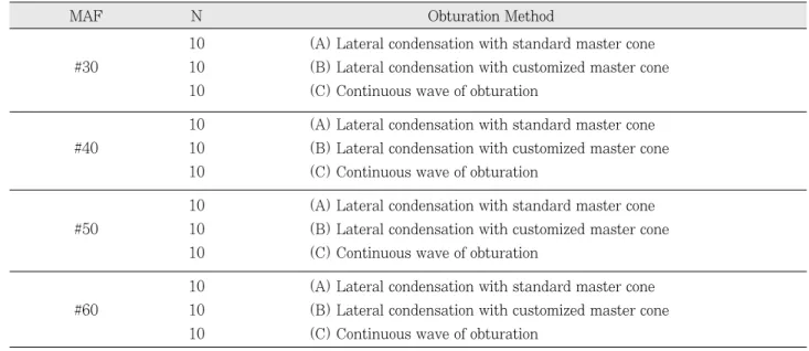
120개의 실험치아를 MAF(Master Apical File)의 크기 에 따라 30, 40, 50, 60번으로 형성한 4개 군으로 나누고, 각 군을 충전방법에 따라 3개 군으로 다시 세분하였다. 즉, 표준화된 master cone으로 측방가압 충전한 군, cus- tomized master cone으로 측방가압 충전한 군, continu- ous wave 충전법으로 충전한 군으로 분류하였다. 각 군의 분류는 Table 1과 같다.
2) 근관형성
치관을 절단한 실험치아는 근관내에 10번 K-flexofile을 삽입하여 치근단공을 확인한 후 치근단공에서 0.5mm를 뺀 길이를 근관작업장으로 결정하였다. 실험군에 따라 MAF(Master Apical File)를 각각 30, 40, 50, 60번으로 형성한 후 통법의 step-back 방법으로 근관을 형성하였으 며, 근관의 치경부는 3, 4번 Gates-Glidden drill로 확대, 형성하였다. 근관세척은 5.25% 차아염소산나트륨 용액을 사용하였으며, step-back 방법의 매 단계마다 10번 K- flexofile로 치근단공을 확인하였다.
3) 근관충전
(1) 표준화된 master cone을 사용한 측방가압법 근관형성이 완료된 후 paper point로 근관을 건조시키고, 형성된 MAF(즉, 30, 40, 50, 60번)에 해당하는 표준화된
Table 1. Classification of Experimental Groups
10 (A) Lateral condensation with standard master cone
#30 10 (B) Lateral condensation with customized master cone 10 (C) Continuous wave of obturation
10 (A) Lateral condensation with standard master cone
#40 10 (B) Lateral condensation with customized master cone 10 (C) Continuous wave of obturation
10 (A) Lateral condensation with standard master cone
#50 10 (B) Lateral condensation with customized master cone 10 (C) Continuous wave of obturation
10 (A) Lateral condensation with standard master cone
#60 10 (B) Lateral condensation with customized master cone 10 (C) Continuous wave of obturation
*MAF ; Master Apical File
MAF N Obturation Method
gutta-percha master cone을 선택, 작업장 길이까지 시적 하여 tugback을 확인한 후 master cone에 AH-26을 도포 하여 근관에 삽입하였다. 이후 2, 3, 4번 finger spreader 와 accessory cone을 사용하여 통법의 측방가압법을 시행 한 뒤 근관와동입구에서 3mm 하방까지 잉여 충전물을 제 거하였다.
(2) Customized master cone을 사용한 측방가압법 작업장보다 2�3mm 짧게 들어가는 표준화된 gutta- percha master cone을 선택하여 cone의 끝부분 2�3mm 를 chloroform에 1�2초간 연화시킨 후, 작업장 길이만큼 근관내에 삽입하여 치근단부의 인상을 채득하였다. 이렇게 제작된 customized master cone은 chloroform의 기화를 위해 5분간 공기건조시킨 후 paper point로 건조시킨 근관 내에 AH-26을 도포하여 삽입하였다. 이후 전과 동일한 방 법으로 측방가압법을 시행하였다.
(3) Continuous wave 충전법
근관의 작업장 길이보다 4mm 짧게 들어가는 Buchanan plugger를 선택하여 AH-26을 도포한 비표준화된 gutta- percha cone을 근관내에 위치시켰다. System B의 온도를 200℃, 출력을 10에 맞춘 뒤 가열된 Buchanan plugger로 binding point 보다 4mm 짧은 곳 까지 삽입, touch switch를 놓은 상태에서 binding point 까지 수직가압한 후 20초간 그 위치에서 유지시켰다. 그 후 switch를 누른 상태에서 plugger와 gutta-percha를 제거한 뒤, 나머지 부 위는 연화온도를 160℃로 설정한 Obtura Ⅱ로 충전하였 다.
4) 미세누출실험
실험치아들은 근관와동 입구를 IRM(The L.D., Caulk, Dentsply, U.S.A.)으로 충전하고, sealer의 경화를 위해 100% 습도하 실온에서 2일간 보관하였다. 이후 치근단 2mm를 제외한 나머지 부위를 nail polish로 2회 도포하였 다.
미세누출실험을 위해 resorcinol-formaldehyde resin을 제작하여 실험치아에 침투되도록 하였다. Resorcinol- formaldehyde resin은 formaldehyde 용액을 KOH를 이 용하여 pH 8.2로 맞춘 뒤 2ml 당 1.3g의 resorcinol과 혼 합하여 제작하였다. 준비된 resorcinol-formaldehyde resin 용액에 실험치아를 담가 레진이 침투되도록 4℃에서 5일간 보관하였으며 이후 치아를 용액에 꺼내어 상온에서 4일간 방치함으로써 레진의 경화를 유도하였다.
5) 치아의 절단 및 절단면 관찰
레진의 침투가 완료된 실험치아들은 치근면에 도포된
nail polish를 제거하고 epoxy resin에 포매한 뒤, low speed microtome을 이용하여 해부학적 근첨에서 1.5mm(Level 1), 2.5mm(Level 2), 3.5mm(Level 3) 떨어진 위치에서 수평절단하였다.
수평절단한 시편의 절단면은 stereomicroscope (Olympus, Japan)으로 40배 확대 관찰한 뒤 사진촬영하 여 이를 computer scanner로 scanning하였다. Scanning 한 image에서 전체 근관면적에 대한 레진침투 면적을 Sigmascan Pro 5/Image softwareTM(Jandel, Scientific software, San Rafael, CA, U.S.A.)를 이용하여 측정한 후 누출도를 평가하였다.
6) 누출률의 측정 및 평가
누출률(%)은 전체 근관면적에 대한 레진침투 면적을 백 분율로 계산하였으며, 이를 WINKS 4.1c Professional Edition(TexaSoftTM, U.S.A) 분석 프로그램을 이용하여 일원변량분석법(One-way ANOVA)과 Newman-Keuls multiple comparisons test로 각 군간의 유의성을 검정하 였다.
Ⅲ. 실험성적
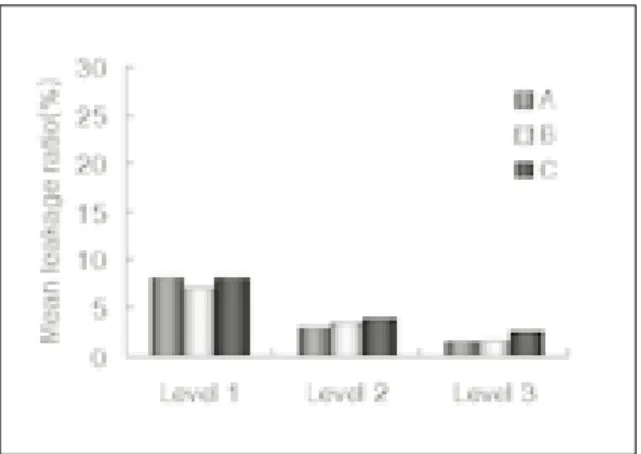
MAF(Master Apical File)가 30번인 군에서는 Level 1, Level 2, Level 3으로 진행할수록 평균누출률이 감소하 였으나, 각 Level에서 3가지 충전방법 간에 평균누출률에 는 큰 차이가 없었으며(Table 2, Fig. 1) 통계분석결과 유 의성이 없었다.
MAF 40번인 군에서는 customized master cone으로 측방가압 충전한 군이 모든 Level에서 평균누출률이 가장 낮았으며 Level 2를 제외하고는 표준화된 master cone으 로 측방가압 충전한 군에서 평균누출률이 가장 높았고, Level 2에서는 continuous wave 충전법으로 충전한 군의 누출이 가장 높았으나(Table 2, Fig. 2), 각 군간에 통계학 적 유의성은 없었다(p>0.05).
MAF 50번인 군에서는 Level 1에서 표준화된 master cone으로 측방가압 충전한 군의 평균누출률이 가장 높았으 며 이는 나머지 두 충전방법과 유의한 차이를 보였다 (p<0.05). 모든 Level에서 customized master cone으로 측방가압 충전한 군의 평균누출률이 가장 낮았으며, Level 2에서는 표준화된 master cone으로 측방가압 충전한 군 이, Level 3에서는 continuous wave 충전법을 사용한 군 의 평균누출률이 가장 높았으나 Level 2, 3에서는 통계학 적 유의성이 없었다(Table 2, Fig. 3).
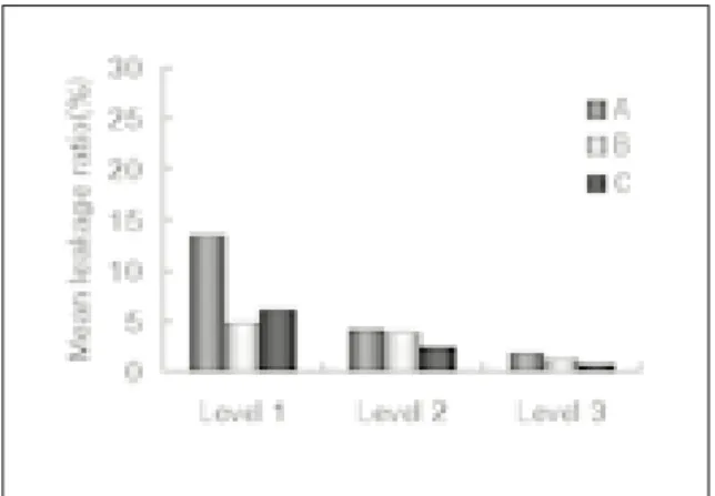
MAF 60번인 군에서는 모든 Level에서 표준화된 mas- ter cone으로 측방가압 충전한 군의 평균누출률이 가장 높 았으며, Level 1에서는 customized master cone으로 측
방가압 충전한 군이, Level 2, 3에서는 continuous wave 충전법으로 충전한 군의 평균누출률이 가장 낮았다(Table 2, Fig. 4). 유의성 검정결과 Level 1, 2에서는 통계학적 유의성이 없었으나, Level 3에서 평균누출률이 가장 낮은
것으로 나타난 continuous wave 충전법을 사용한 군과 표 준화된 master cone으로 측방가압 충전한 군 사이에는 유 의한 차이를 보였다(p<0.05).
Table 2. Mean leakage ratio (%) at 3 Levels
A 8.22±5.35 2.98±2.38 1.55±1.05
#30 B 6.89±9.75 3.54±5.77 1.56±1.10
C 8.20±8.52 3.94±2.31 2.52±1.19
A 12.53±10.62 5.02±4.87 2.40±3.13
#40 B 7.11±10.34 1.99±2.02 0.42±0.42
C 8.39±3.90 5.14±3.29 1.89±1.47
A 25.17±22.73 2.84±3.51 1.02±0.75
#50 B 3.57±3.32 1.99±2.34 0.73±0.84
C 6.14±7.30 2.64±1.95 2.11±2.13
A 13.58±13.31 4.19±3.45 1.81±1.22
#60 B 4.77±3.45 3.88±3.94 1.07±0.83
C 6.04±6.88 2.44±3.46 0.74±0.67
A : Lateral condensation with standard master cone B : Lateral condensation with customized master cone C : Continuous wave of obturation
Level 1 : 1.5mm from the apex, Level 2 : 2.5mm from the apex, Level 3 : 3.5mm from the apex
MAF Level 1 Level 2 Level 3
(Average±standard deviation)
Fig. 1.Mean leakage ratio(%) at 3 Levels (MAF #30) A : Lateral condensation with standard master cone B : Lateral condensation with customized master
cone
C : Continuous wave of obturation
Fig. 2.Mean leakage ratio(%) at 3 Levels (MAF #40) A : Lateral condensation with standard master cone B : Lateral condensation with customized master
cone
C : Continuous wave of obturation
Ⅳ. 총괄 및 고안
근단부의 인상을 채득하여 customized master cone을 제작한 뒤 충전을 시행하는 방법은 근관형성된 근단부의 형 태가 규격화된 gutta-percha와 같이 둥글지 않은 경우에
근단부에서 근관벽과 gutta-percha와의 적합성을 좋게함 으로써 실러로 충전될 면적을 감소시키게 되는데, 이는 후 에 실러의 용해로 인해 발생될 치근단 밀폐의 손상을 감소 시키게 된다13). 이러한 customized master cone을 제작하 는 방법은 크게 용제를 이용하는 방법과 열을 이용하는 방 Table 3. Statistical analysis of mean leakage ratio(%) in experimental groups
Level 1 F value 0.09 1.02 7.19 2.88
P value 0.9164 0.3724 0.0031* 0.0733
Level 2 Fvalue 0.16 2.48 0.28 0.66
P value 0.8565 0.1026 0.7614 0.5253
Level 3 Fvalue 2.53 2.6 2.73 3.45
P value 0.0986 0.0928 0.0835 0.0462*
* statistically significant at P<0.05
MAF(Master Apical File) #30 #40 #50 #60
Table 4. Statistical analysis of mean leakage ratio(%) between groups : Newman-Keuls multiple comparisons test
A * * ND *
B * ND ND ND
C * ND * ND
* statistically significant at P<0.05 ND ; no statistical difference
MAF #50, Level 1 MAF #60, Level 3
A(Standard) B(Customized) C(Continuous) A(Standard) B(Customized) C(Continuous) Fig. 3.Mean leakage ratio(%) at 3 Levels (MAF #50)
A : Lateral condensation with standard master cone B : Lateral condensation with customized master
cone
C : Continuous wave of obturation
Fig. 4.Mean leakage ratio(%) at 3 Levels (MAF #60) A : Lateral condensation with standard master cone B : Lateral condensation with customized master
cone
C : Continuous wave of obturation
법으로 나눌 수 있다.
Gutta-percha의 연화에 사용될 수 있는 용제로는 chlo- roform, eucalyptol, halothane, xylene, orange ter- penes 등이 있으며 이 중 chloroform이 가장 흔히 사용되 는 용제이다. Chloroform으로 gutta-percha를 연화시켜 customized master cone을 제작시에는 충전물의 수축이 문제가 되었으나14)이는 chloroform의 적용방법에 대한 고 려가 선행되어야 한다.
Chloroform의 사용시에 발생되는 충전물의 수축은 사용 하는 chloroform의 양과 밀접한 관련이 있다. Keane과 Harrington15)은 chloroform의 사용량에 따른 근단부 폐쇄 효과를 연구하였는데, master cone의 근단부 4�5mm를 chloroform에 1초간 3회, 2회, 1회 각각 dipping하고 근단 부 인상을 채득한 뒤 충전하였을 때 chloroform을 많이 사 용할수록 치근단 누출의 정도가 증가하는 결과를 얻을 수 있었다. 즉, chloroform을 사용한 이전의 연구들에서 많은 수축과 누출을 보였던 것은 chloroform의 사용량이 많았기 때문이며, customized master cone의 제작을 위해 근관을 형상화하는데는 1초간 dipping하는 것으로 충분하다고 하 였다. 본 실험에서는 customized master cone을 제작하기 위해 cone의 근단부 2�3mm를 chloroform에 1�2초간 연화시켰으며 충전을 시작하기 전에 chloroform의 기화를 위해 5분간 공기건조시킴으로써 chloroform으로 인한 충전 물의 수축을 최소화하고자 하였다.
Chloroform을 사용하여 customized master cone을 제 작시 수축을 최소화하기 위한 또 다른 고려사항은 근관충전 을 시작하기 전에 제작된 master cone으로부터 chloro- form이 충분히 기화할 시간을 주었는지를 들 수 있다. 앞에 서 언급한 Keane과 Harrington의 연구15)에서 3회 dip- ping한 군에서는 충전을 시행하기 직전에 3번째 dipping을 한 뒤 근관에 적용시키고 바로 근관충전 과정을 진행함으로 써 chloroform이 근관 밖에서 충분히 기화할 시간을 부여하 지 못한 것을 누출 증가의 원인이라고 하였다. Metzger16)는 master cone을 chloroform에 연화시켰을 때 cone의 plas- ticity가 상실되는 시간을 chloroform이 기화되는 속도와 혼동할 수 있음을 지적하였는데, 실제로 cone의 plasticity 는 건조 후 15초 이내에 대부분이 상실되나, chloroform의 기화는 3분 후 62%가 진행된다고 하였다. 따라서 chloro- form에 dipping한 뒤 gutta-percha cone에 충분한 구강외 건조시간을 부여하는 것이 필요하다.
치근단 부위의 근관형성의 크기를 어느 정도로 할 것인가 를 결정하는데 있어서 Wein3)은 근관형성 하기 전 초기 근 관에 적합되었던 크기의 파일(IAF; Initial Apical File)에 서 3단계 큰 파일의 크기만큼 형성하는 것을 추천하였는데 이 때의 파일을 MAF(Master Apical File)라고 하였다.
이것은 근단부 형성이 완전히 이루어졌거나 직선적인 근관
에서는 대부분 적용될 수 있으나 치근단 부위에 흡수가 있 거나 의원성으로 근단공이 이미 넓어져있는 만곡근관에서 는 적용하기 어려운 경우가 많다. 근단공 부위가 적절히 세 척, 밀폐되기 위해서는 최소 20번이나 25번 이상으로 기구 조작하는 것이 필요하지만 근단공이 넓어질수록 근단공의 찢어짐(tearing)이나 근단공 부위에서 근관 충전물 주위로 의 누출 발생 가능성이 커지게 된다17). 따라서 근단부의 근 관형성시에는 근단공을 넓히는 것이 목적이 아니라 깨끗이 하는 것이 목적임을 잊지 말아야 한다. 특히 만곡된 근관에 서 큰 파일을 근단부 형성시 사용하게 되면 치근단 부위의
“zip”이나“elbow”, 또는 근단부 천공과 같이 충전을 어렵 게 만드는 상황을 유발하게 된다18). 모든 근관의 90% 정도 에서 만곡이 관찰됨을 볼 때19) 근단부 형성의 크기, 즉 MAF의 크기가 커지면 보통의 표준화된 master cone으로 는 치근단 부위의 완전한 밀폐를 기대하기 어려운 경우가 많아진다고 볼 수 있다.
본 실험에서 실험치아의 해부학적 근첨에서 1.5mm 떨어 진 부위인 Level 1에서의 평균 누출률을 보면 표준화된 master cone으로 측방가압 충전한 경우, MAF의 크기가 증가할수록 누출률이 증가하였음을 확인할 수 있었다. 이에 비교하여 customized master cone으로 측방가압 충전한 군과 continuous wave 충전법을 사용한 군의 경우는 MAF의 크기에 관계없이 대체로 비슷한 평균 누출률을 나 타내었다. 따라서 MAF의 크기가 증가할수록 표준화된 master cone으로 측방가압 충전한 군과 나머지 두 충전법 간의 평균 누출률의 차이는 점점 증가되었으며, MAF가 50 번인 경우에는 통계학적으로 유의한 차이를 나타내었다. 그 러나 오히려 60번인 경우에는 Level 1에서 유의성있는 누 출률의 차이를 보이지 않았는데, 이는 MAF를 60번으로 형 성한 실험치아의 경우 근관이 비교적 크고 직선적인 경우가 많았기 때문인 것으로 생각되었다.
1967년 Schilder에 의해 소개된 수직가압법20)은 기구를 열에 달구어 사용하였던 고전적인 방법으로는 시간소모와 기술적 어려움이 존재하여 이후에 Endotec(Caulk, Milford, DE)이나 Touch’n Heat(Analytic Technology, U.S.A.)과 같은 전기를 이용한 장치들이 개발되었으나21) System B(Analytic Technology, U.S.A.)가 소개되면서 continuous wave 충전법이 가능하게 되어 빠르고 삼차원 적인 수직가압 충전을 할 수 있게 되었다.
Continuous wave 충전법은 작업장보다 4mm 짧게 들어 가는 Buchanan plugger를 미리 선택하여 이에 맞는 비표 준화된 gutta-percha cone을 선택, 사실상 1개의 cone이 근단부의 충전을 담당하게 된다. 따라서 근단협착부로부터 매끈하고 일정한 경사도를 갖는 형태로 근관이 형성된 후에 이에 잘 적합되는 cone을 선택하는 것이 중요한데22), 신, 최 등23)의 연구에 의하면 협설측으로 넓은 근관에서는 contin-
uous wave 충전법을 사용했을 때 sealer로 채워진 공간이 컸음을 밝힌 바 있다. 본 연구에서도 continuous wave 충 전법을 사용한 군에서 gutta-percha는 근관내에서 둥글고 균질한 형태로 충전되었으나 근관벽의 불규칙한 부위는 대 부분 sealer로 채워져 있었음을 알 수 있었다. 현재 다양한 경사도를 가지는(.04, .06, .08, .10, .12 taper) rotary Ni-Ti file을 근관형성에 사용했을 경우에는 형성된 근관의 경사도에 맞게 규격화된 gutta-percha master cone을 선 택함으로써 쉽고 정확히 continuous wave 충전법을 시행 할 수 있을 것으로 생각된다.
본 연구의 결과, 근단부 형성의 크기가 커질수록 기존의 규격화된 master cone의“tug-back”을 이용한 측방가압법 으로는 효과적인 치근단 밀폐를 얻기가 어려웠으며, 이는 근단부 형성에 사용된 기구의 크기가 커질수록 규격화된 gutta-percha cone의 형태와 같이 매끈하고 둥근형태로 근단부 형성을 할 수 없게 됨을 미루어 생각해 볼 수 있다.
따라서 근단부 형성이 50번 파일 크기 이상이 될 경우에는 근단부 형태를 복제한 customized master cone을 제작, 충전하거나 continuous wave 충전법과 같은 열연화 가압 충전법을 사용하는 것이 치근단 밀폐효과를 증가시킬 수 있 을 것으로 생각된다.
Ⅴ. 결 론
본 연구는 근단부 크기에 따른 근관 충전법 간의 치근단 폐쇄효과를 비교하기 위해 120개 소구치를 MAF(Master Apical File)의 크기에 따라 30, 40, 50, 60번으로 형성한 군으로 나누고, 각 군을 다시 표준화된 master cone을 이 용하여 측방가압 충전한 군, customized master cone으로 측방가압 충전한 군, continuous wave 충전법으로 충전한 군으로 세분하여 근관충전한 다음 resorcinol-formalde- hyde resin을 이용한 미세누출 실험방법으로 해부학적 근 첨에서 1.5mm(Level 1), 2.5mm(Level 2), 3.5mm (Level 3) 떨어진 치근단 부위의 평균누출률을 측정하여 다 음과 같은 결과를 얻었다.
1. MAF가 30번인 군에서 평균누출률은 Level 1, 2, 3에 서 세가지 충전방법 간에 큰 차이가 없었다.
2. MAF가 40번인 군에서 평균누출률은 Level 1, 2, 3에 서 customized master cone으로 측방가압 충전한 군이 가장 낮았으며, Level 1, 3에서는 표준화된 master cone으로 측방가압 충전한 군이, Level 2에서는 con- tinuous wave 충전법으로 충전한 군의 평균누출률이 가 장 높았으나 통계학적 유의성은 없었다.
3. MAF가 50번인 군에서 평균누출률은 Level 1에서 cus- tomized master cone으로 측방가압 충전한 군과 con- tinuous wave 충전법으로 충전한 군이 표준화된 mas-
ter cone으로 측방가압 충전한 군보다 낮았으며, 통계학 적으로 유의한 차이를 보였다(p<0.05). Level 2와 3에 서는 각 군간에 유의한 차이가 없었다.
4. MAF가 60번인 군에서 평균누출률은 Level 1, 2에서 customized master cone으로 측방가압 충전한 군과 continuous wave 충전법으로 충전한 군이 표준화된 master cone으로 측방가압 충전한 군보다 낮았으나 통 계학적 유의성이 없었으며, Level 3에서는 continuous wave 충전법과 표준화된 master cone으로 측방가압 충 전한 군 사이에 통계학적으로 유의한 차이를 보였다 (p<0.05).
본 연구 결과 MAF가 50번 이상인 근관에서는 표준화된 master cone보다는 customized master cone을 제작하여 근관충전하거나 continuous wave 충전법으로 충전하는 경 우 치근단 누출을 감소시킬 수 있을 것으로 판단된다.
참고문헌
1. Schilder H: Cleaning and shaping the root canal. Dent Clin North Am, 18:269, 1974.
2. Dow PR, Ingle JI: Isotope determination of root canal failure. Oral Surg Oral Med Oral Pathol, 8:1100-1104, 1955.
3. Wein FS: Endodontic Therapy. 5th ed., Mosby, 14, 317, 435-436, 1996.
4. Callahan JR: Rosin solution for the sealing of the dentinal tubuli and as an adjuvant in filling the root canals. J Allied Dent Soc, 9:53, 1914.
5. Wong M, Peters DD, Lorton L, Bernier EN:
Comparison of gutta-percha filling techniques: three chloroform gutta-percha filling techniques Part 2. J Endodon, 8:4-9, 1982.
6. Morse DR, Martell B, Pike GC, Fantasia J, Esposito JV, Furst LM: A Comparative Tissue Toxicity Evaluation of Gutta-Percha Root Canal Sealers. Part
Ⅰ. Six-hour Findings. J Endodon, 10:246-9, 1984.
7. Barbosa SV, Burkard DH, Spa�ngberg LSW: Cytotoxic Effects of Gutta-percha Solvents. J Endodon, 20:6-8, 1994.
8. Beatty RG, Zakariasen KL: Apical leakage associated with three obturation techniques in large and small root canals. Int Endodon J, 17:67-72, 1984.
9. Gutmann JL, Witherspoon DE: Obturation of the Cleaned and Shaped Root Canal System. In Cohen S, Burns RC, editor: Pathways of the pulp, 7th ed., Mosby, 258-259, 327, 1998.
10. Buchanan LS: The continuous wave of obturation tech- nique: ‘Centered’condensation of warm gutta-percha in 12 seconds. Dentistry Today, Jan, 1996.
11. Narracott P: An in vitro comparison of the single cone and lateral condensation techniques using ‘friction-fit- ted’and ‘solvent dip-fitted’primary gutta-percha cones. Aust Dent J, 34:49-51, 1989.
12. Metzger Z, Nissan R, Tagger M, Tamse A: Apical Seal by Customized versus Standardized Master Cones: A Comparative Study in Flat and Round Canals. J Endodon, 14:381-384, 1988.
13. Christie WH, Peikoff MD: Direct impression technique;
Sealing prepared apical foramen. J Canad Dent Assn, 3:174-181, 1980.
14. Zakariasen KL, Stadem PS: Microleakage associated with modified eucapercha and chloropercha root-canal- filling techniques. Int Endodon J, 15:67-70, 1982.
15. Keane KM, Harrington GW: The Use of Chloroform- softened Gutta-percha Master Cone and Its Effect on the Apical Seal. J Endodon, 10:57-63, 1984.
16. Metzger Z, Assif O, Tamse A: Residual Chloroform and Plasticity in Customized Gutta-percha Master Cones. J Endodon, 14:546-549, 1998.
17. West JD, Roane JB: Cleaning and Shaping the Root Canal System. In Cohen S, Burns RC, editor:
Pathways of the pulp, 7th ed., Mosby, 232, 1998.
18. Luiten DJ, Morgan LA, Baumgartner JC, Marshall JG:
A Comparison of Four Instrumentation Techniques on
Apical Canal Transportation. J Endodon, 21:26-32, 1995.
19. Christie WH, Peikoff MD: Conservative treatment of apical foramen; New root canal techniques. J Canad Dent Assn, 3:183-188, 1980.
20. 신정희, 최호영, 박상진, 최경규, 최기운: 근단공이 넓은 치아 의 근관충전방법에 따른 치근단 폐쇄효과에 관한 연구. 경희치 대논문집, 21:1-16, 1999.
21. Ingle JI, West JD: Obturation of the radicular space.
In Ingle JI, Bakland LK, editor: Endodontics 4th ed., A Lea & Febiger Book, 266, 1994.
22. Schilder H.:Filling root canals in three dimensions.
Dent Clin North Am, 11:723-44, 1967.
23. Jerome CE: Warm Vertical Gutta-percha Obturation:
A Technique Update. J Endodon, 20:97-99, 1994.
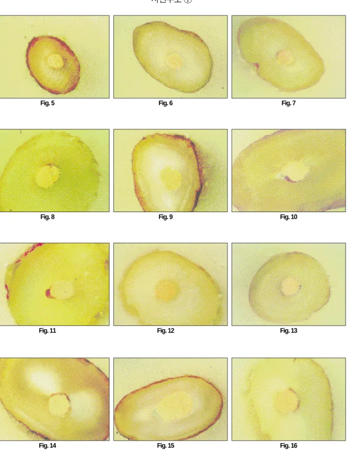
사진부도 설명
Fig. 5. Representative photograph of the group using lateral condensation with standard master cone at MAF
#30, Level 1 (×40).
Fig. 6. Representative photograph of the group using lateral condensation with customized master cone at MAF #30, Level 1 (×40).
Fig. 7. Representative photograph of the group using continuous wave of obturation at MAF #30, Level 1 (×
40).
Fig. 8. Representative photograph of the group using lateral condensation with standard master cone at MAF
#40, Level 1 (×40).
Fig. 9. Representative photograph of the group using lateral condensation with customized master cone at MAF #40, Level 1 (×40).
Fig.10. Representative photograph of the group using continuous wave of obturation at MAF #40, Level 1 (×
40).
Fig.11. Representative photograph of the group using lateral condensation with standard master cone at MAF
#50, Level 1 (×40).
Fig.12. Representative photograph of the group using lateral condensation with master cone at MAF #50, Level 1 (×40).
Fig. 13. Representative photograph of the group using continuous wave of obturation at MAF #50, Level 1 (×
40).
Fig.14. Representative photograph of the group using lateral condensation with standard master cone at MAF
#60, Level 1 (×40).
Fig.15. Representative photograph of the group using lateral condensation with customized master cone at MAF
#60, Level 1 (×40).
Fig.16. Representative photograph of the group using continuous wave of obturation at MAF #60, Level 1 (×
40).
사진부도 ①
Fig. 5 Fig. 6 Fig. 7
Fig. 8 Fig. 9 Fig. 10
Fig. 11 Fig. 12 Fig. 13
Fig. 14 Fig. 15 Fig. 16