2020 Keimyung University School of Medicine This is an open-access article distributed under the terms of the Creative Commons Attribution license (http://creativecommons.org/licenses/by/4.0/), which permits unrestricted use, distribution, and reproduction in any medium, provided the original work is properly cited.
Femoral Anteversion: Transverse Section Versus Axial Oblique Section
Jong Hyuk Jeon, Si Wook Lee, Kwang Soon Song, Ki Choer Bae
Department of Orthopedic Surgery, Keimyung University School of Medicine, Daegu, Korea
Introduction
An abnormal femoral anteversion angle is associated with a variety of clinical problems ranging from in-toeing gait in early childhood to disabling osteoarthri- tis of the hip and knee in adulthoods. Accurate evaluation of femoral anteversion is essential to inform the decision for surgical correction. In children, the indica- tion for surgery is an age of eight years or older with the measured anteversion above 50 degrees and medial hip rotation above 85 degrees [1].
Many imaging methods have been used to measure femoral anteversion, such as two-dimensional (2D) computed tomography (CT), magnetic reso- nance (MR) or ultrasound (US) imaging, and three-dimensional (3D) model- ing [2-9]. More recently, measurement of axial-oblique reformations parallel to the long axis of the femoral neck was introduced and reported to lead to more accurate measurement of femoral anteversion than conventional 2D imaging [10-12]. However, there is still no consensus on the imaging modality of choice.
This study aimed to define a more accurate CT scanning method for mea- surement of the anteversion angle of the femoral neck.
Received: March 24, 2020 Revised: May 13, 2020 Accepted: May 15, 2020 Corresponding Author:
Si Wook lee, M.D., Ph.D.
Department of Orthopedic Surgery, Keimyung University School of Medicine, Dongsan Medical Center, 1035, Dalgubeol-daero, Dalseo-Gu, Daegu, 42601, Korea
Tel:+82-53-258-7927 E-mail: [email protected]
pISSN 2092-8335 · eISSN 2733-5380 Keimyung Med J 2020 39(2):72-78 https://doi.org/10.46308/kmj.2020.00045
Original Article
This study was aimed to define a more accurate computed tomography (CT) scan- ning method for measurement of the anteversion angle of the femoral neck. Five models of the femur, consisting of three models of saw bones and two of cadaveric bones, were used to measure femoral anteversion. Real femoral anteversion was measured with photographs taken from the superior aspect of the femoral neck after placing the specimen in the position that both posterior condyles rested on the sur- face of the table and the center of the femoral head and center of the intercondylar notch were aligned in a single line. Femoral anteversion using the transverse section of CT (CT1) and the axial oblique section of CT (CT2) were obtained. Three experi- enced orthopedic surgeons measured the anteversion of five bone models using the photographs and two CT scans, three times each with a week interval between mea- surements. A total of 45 measurements were obtained. The intraclass correlation co- efficient (ICC) was used to compare anteversion measurements between the differ- ent methods. Femoral anteversion measured in photographs was correlated with measurements on CT1 and CT2. However, CT2 more closely approximated the real anteversion than did CT1 (ICC; CT1 = 0.824, CT2 = 0.937). Inter-observer and in- tra-observer biases were not found (ICC ≥ 0.952). The axial oblique image more closely approximated the real femoral anteversion than did the transverse sectional image. Measurement of femoral anteversion using axial oblique CT is recommended over conventional transverse sectional CT.Keywords: Axial oblique section, Transverse section, Femoral anteversion
Materials and methods
Five models of the femur, consisting of three models of saw bones and two of cadaveric bones, were used to measure fem- oral anteversion.
Photographs of all five bone models were taken from the superior aspect of the femoral neck after placement of the specimen at the edge of the table on the horizontal surface, such that the inferior end of both femoral condyles rested on the surface of the table. For measurement of the real femoral anteversion, the specimen was placed parallel to the mechani- cal axis such that that the center of the femoral head and cen- ter of the intercondylar notch were aligned in a single line (Fig. 1). Two different CT scans were obtained. The first was a
single transverse sectional image of the femoral neck as it passes just below the inferior border of the femoral head (CT1), as described by Sugano et al. [13]. The second was an axial-oblique image parallel to the long axis of the femoral neck (CT2), as described by Tomczak [10] (Fig. 2,3). In addi- tion, we obtained another image in which the posterior sur- face of the medial and lateral condyles was clearly visible, and femoral anteversion was measured in each series (Fig. 4).
Two major axes, the neck and posterior condyle, were used as reference lines and defined as follows. The neck axis was defined as the center line drawn between two lines tangential to the upper and lower surfaces of the femoral head (or the most proximal portion of the inferior neck just below the in- ferior border of the femoral head on CT1) and greater tro- chanter (Fig. 5). The posterior condylar axis was defined as the line connecting the most posterior surfaces of the both femoral condyles. In photographs, the horizontal surface rep- resented the posterior condylar axis. The femoral anteversion angle was defined as the angle between the neck axis and the posterior condylar axis (Fig. 5).
All photographs and CT images were printed, and the fem- oral anteversion angle was measured by manually in accor- dance with the Kingsley Olmstead [14] method using a goni- ometer, ruler, and pen with the same reference lines. The angle (alpha) between the neck axis and horizontal reference line, and the angle (beta) between the posterior condylar axis and horizontal reference line were measured separately by the method of Tomczak [10] (Fig. 6). The femoral anteversion an- gle was calculated by either adding or subtracting the beta an-
Fig. 1. Photographs of femoral model. The specimen was placedparallel to the mechanical axis that the center of the femoral head and center of the intercondylar notch aligned in single line.
Fig. 2. Single transverse sectional image of femoral neck. Transverse line passes just below at the inferior border of femoral head.
gle from the alpha angle, according to the rotation type. All measurements were repeated three times with at least a 1-week interval between measurements by each of three experienced orthopedic surgeons, to identify intra- and inter-observer vari- ability of the techniques. Each of three doctors measured all anteversion angles with blinding from their previous records and results of other doctors. A total of 45 measurements were obtained and used for statistical evaluation. Intra-observer bias, inter-observer bias, and the results of the two different CT methods were evaluated and compared with the results from the actual photographs through intraclass correlation co- efficient (ICC) tests. All analyses were performed with SPSS version 2.0.
Results
The femoral anteversion angles of each of the five bone models, as measured three times by each observer, were used to assess intra-observer bias. The ICC test revealed no evi- dence of intra-observer bias (ICC ≥ 0.952) (Table 1). The av- erage value of the femoral anteversion angle measured by the three observers was used to evaluate inter-observer bias. The ICC test revealed no evidence of inter-observer bias (ICC ≥ 0.993) (Table 2). Fifteen measurements (average of three mea-
Fig. 4. Image that the posterior surface of the medial and lateralcondyle were clearly visible.
Fig. 5. Two major axes and femoral anteversion angle. (A)
Anteversion angle. (B) Neck axis. (C) Posterior condylar axis. The neck axis (B) was defined as the center line drawn between two lines that is tangential to the upper and lower surface of femoral head and greater trochanter. The posterior condylar axis (C) was defined as a connecting line of the most posterior surface of the both femoral condyle. The femoral anteversion angle (A) was defined as the angle between the neck axis and the posterior condylar axis.
Fig. 3. Axial-oblique image of femoral neck. Oblique line is parallel to the long axis of femoral neck.
Fig. 6. Methods to calculate femoral anteversion angle. Angle (alpha) between the neck axis and horizontal reference line and angle (beta)
between posterior condylar axis and horizontal reference line were measured separately. Femoral anteversion angle was calculated by subtraction or addition of the beta angle from the alpha angle according to rotation type. In this photograph, the anterversion angle can be calculated by addition of beta angle from the alpha angle.
Table 1. Intraclass correlation cefficient [1.1] for intraobserver bias and comparison of methods
Method Obs-trial Obs-trial Obs-trial ICC* (95%CI)† F (p-Value)
Clinical Obs1-1 Obs1-2 Obs1-3 0.952 (0.806,0.994) 60.209 (< 0.001)
Obs2-1 Obs2-2 Obs2-3 0.967 (0.864,0.996) 89.429 (< 0.001)
Obs3-1 Obs3-2 Obs3-3 0.957 (0.825,0.995) 67.733 (< 0.001)
CT 1 Obs1-1 Obs1-2 Obs1-3 0.990 (0.956,0.999) 296.656 (< 0.001)
Obs2-1 Obs2-2 Obs2-3 0.972 (0.881,0.997) 103.291 (< 0.001)
Obs3-1 Obs3-2 Obs3-3 0.970 (0.876,0.997) 99.311 (< 0.001)
CT 2 Obs1-1 Obs1-2 Obs1-3 0.994 (0.975,0.999) 517.143 (< 0.001)
Obs2-1 Obs2-2 Obs2-3 0.994 (0.975,0.999) 521.384 (< 0.001)
Obs3-1 Obs3-2 Obs3-3 0.993 (0.970,0.999) 436.743 (< 0.001)
*Intraclass correlation coefficient. †95% confidence interval.
Table 2. Intraclass correlation coefficient [3.1] for interobserver bias and comparison of methods
Method Obs-trial Obs-trial Obs-trial ICC* (95%CI)† F (p-Value)
Clinical Obs1-mean Obs2-mean Obs3-mean 0.995 (0.974,0.999) 195.284 (< 0.001)
CT 1 Obs1-mean Obs2-mean Obs3-mean 0.994 (0.968,0.999) 195.192 (< 0.001)
CT 2 Obs1-mean Obs2-mean Obs3-mean 0.999 (0.996,1.000) 517.143 (< 0.001)
*Intraclass correlation coefficient. †95% confidence interval.
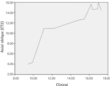
surements for each observer in the five bone models) for each CT method were evaluated and compared with measurements from the actual photographs through ICC tests. The femoral antever- sion angle measured on the photos was significantly correlated with the femoral anteversion angle measured on each type of CT scan (Table 3). However, CT 2 more closely approximated the clinical method than CT1. (ICC, CT1 = 0.824, CT2 = 0.937) (Fig. 7,8).
Table 3. Intraclass correlation coefficient [3.1] for comparison of
clinical methods with each type of CT scan
Method CT scan type ICC* (95%CI)† F (p-Value) Clinical CT 1 0.824 (0.475,0.941) 5.675 (< 0.001) Clinical CT 2 0.937 (0.811,0.979) 15.788 (< 0.001)
*Intraclass correlation coefficient. †95% confidence interval.
Discussion
The femoral anteversion angle can be defined as the angle formed by the femoral condyle plane and a plane passing through the center of the neck and femoral head. If the femo- ral condyle plane passes behind the center of the femoral head, neck anteversion is present [8].
On the basis of measurements from 630 dry anatomic fem- oral specimens, Kingsley and Olmstead reported that the mean femoral anteversion angle was 8.0° (range, -20° to 38°).
Usually, the mean femoral anteversion angle is higher in in- fants (mean, 24.4°; range, -10° to 64°) and children (mean, 17.2°; range, -4.5° to 38°) than adults, but the angle gradually diminishes during childhood and adolescence [14].
Rotational problems, when outside of the normal range, are referred to as torsional deformity, and these deformities are relatively common in infancy and childhood. In the vast ma- jority of children, torsional deformities of the lower limb im- prove spontaneously [1]. However, clinical disability can in- troduce cosmetic and functional problems, such as in-toeing gait in early childhood, which can lead to disabling osteoar- thritis of the hip and knee in adults if they persist.
Abnormal femoral anteversion is correctable by rotational osteotomy, but the operation should be performed only in children after the age of eight if they still have an abnormal anteversion angle greater than 50 degrees and medial rotation of the hip greater than 85 degrees [1]. Therefore, precise mea- surement of the real femoral anteversion angle is needed to
inform the decision for surgical correction.
Although direct anatomic measurement of the real femoral anteversion angle is desirable, it may not be possible in clini- cal settings.
Consequently, other accurate and reproducible methods for measuring the femoral anteversion angle have been investi- gated [2-9]. However, these studies have shown that measure- ments can vary according to the observer’s experience, imag- ing modality, measurement method, and reference line [6,8,13,15-18].
CT techniques using single or multiple axial slices are gen- erally favored for the measurement of femoral anteversion, but these methods show variable accuracy because the femo- ral neck is not perfectly cylindrical, and the neck-shaft angle is not always 90 degrees. The accuracy of a single transverse sectional image can be significantly affected by its level on the femoral neck [13]. Anteversion is often underestimated by more proximal sections and overestimated by more distal sections.
To overcome the limitations of conventional 2D imaging methods, researchers have developed a 3D imaging method, and satisfactory results have been reported [8,9]. However, 3D imaging has several drawbacks: 3D rendering is time con- suming and costly. Although 3-D CT is a valuable diagnostic tool in evaluating bony femoral anteversion, it has several limitations such as radiation exposure [19], inefficiency in use in terms of time and technical effort, and high cost. Severe
Fig. 7. Correlation between transverse sectional image andphotograph. The slope of the graph represent the relationship between two parameters. If it is close to 1 (straight line), the correlation between the two is high.
Fig. 8. Correlation between axial oblique image and photograph.
The slope of the graph represent the relationship between two parameters. If it is close to 1 (straight line), the correlation between the two is high.
Clinical 18.00
16.00 14.00 12.00 10.00 8.00
6.00
8.00 10.00 12.00 14.00 16.00 18.00
Trans sectional (CT1)
Clinical 16.00
14.00 12.00 10.00 8.00 6.00 4.00 2.00
8.00 10.00 12.00 14.00 16.00 18.00
Axial obilque (CT2)
deformity of the femoral head or neck-shaft angle or an inap- propriate position makes it difficult to obtain 3-D recon- structed images, but the 2-D CT technique exhibited excellent reliability and clinically acceptable accuracy [20].
Several studies have recommended the assessment of axi- al-oblique reformations parallel to the long axis of the femoral neck using axial CT slices. Tomczak et al measured femoral anteversion angle through the MR image that showed the centers of the head and femoral neck and therefore allowed visualization of the true neck axis by calculating the angle be- tween true neck axis and horizontal reference line [10]. This method has been reported to improve the accuracy of femoral anteversion measurement compared with conventional 2D imaging methods [10-12]. The technique allows for accurate anteversion assessment regardless of patient positioning [11], it and does not require 3D rendering.
CT imaging using the conventional transverse section and the axial oblique section are among the most widely used and cost-effective methods to measure femoral anteversion. How- ever, there is still no consensus on the imaging modality of choice. Sugano et al. found that the transverse section through the most proximal portion of the inferior neck (excluding the head) provides the most accurate estimate of the femoral neck axis [13]. Other authors have suggested that 3D imaging pro- vides more accurate and reliable measurements of femoral anteversion than 2D imaging, and femoral anteversion can be analyzed quantitatively using 3D-CT regardless of patient po- sition [8,9]. More recently, Parikh and Noyes [12] reported that axial oblique images show the closest approximation to true femoral anteversion. However, to our knowledge, no study in the orthopedic literature has compared these tech- niques with an anatomic reference considered to be the most accurate method for the measurement of femoral anteversion.
Thus, we aimed to determine a more accurate CT method to measure the real femoral anteversion angle by comparing conventional (axial) and axial-oblique CT scans with actual clinical photographs of human cadaveric and saw bone fe- murs. The femoral anteversion angle measured by the axi- al-oblique image (CT2) more closely approximated that of the clinical method than did the conventional transverse section- al image (CT1). This finding is consistent with that of Parikh and Noyes [12]. The axial-oblique technique showed good re- producibility with low inter-observer variation (ICC = 0.999) and intra-observer variation (ICC ≥ 0.993). These results might have been affected by the reference lines used in our study. We defined the neck axis in a slightly different way than other studies. Because the shape of the femoral neck is
elliptical, and the shape of the femoral head in a sectional im- age is not a perfect circle, determining the centers of the fem- oral head and neck can vary according to the observer.
It should be noted that our study did not include pediatric femora. Because many hip conditions that require clinical knowledge of femoral anteversion occur in children, evalua- tion of another femoral model that included pediatric femora may have lent more predictive power to our findings. We also did not evaluate a 3D imaging method because of the difficul- ty of determining the centers of the femoral head and neck derived from the process that converts the 2D image into the 3D reconstruction image.
The axial-oblique technique was reproducible and showed greater accuracy in the measurement of femoral anteversion than the single transverse sectional technique. Application of these data to a clinical setting should be carried out sensibly, recognizing that confounding factors such as accompanying disease (e.g., cerebral palsy), variability in technician skills, and radiographic interpretation by clinicians may lead to er- rors in accurate measurement of femoral anteversion
Conclusion
The axial oblique image more closely approximated the real femoral anteversion than the transverse sectional image. Mea- surement of femoral anteversion using axial oblique CT is recommended over conventional transverse sectional CT.
Conflict of interest
All authors declare no conflicts-of-interest related to this article.
References
1. Staheli LT. Torsion--treatment indications. Clin Orthop Relat Res. 1989;247:61-6.
2. Aamodt A, Terjesen T, Eine J, Kvistad KA. Femoral anteversion measured by ultrasound and CT: a comparative study. Skeletal Radiol. 1995;24:105-9.
3. Streit HA. A new method for determination of torsion of the fe- mur. J Bone Joint Surg Am. 1953;35:289-311.
4. Høiseth A, Reikerås O, Fønstelien E. Evaluation of three meth- ods for measurement of femoral neck anteversion. Femoral neck anteversion, definition, measuring methods and errors. Acta Radiol. 1989;30:69-73.
5. Reikerås O, Høiseth A, Reigstad A. Femoral anteversion mea-
sured by the Dunlap/Rippstein and Norman methods. Acta Ra- diol Diagn (Stockh). 1985;26:303-5.
6. Murphy SB, Simon SR, Kijewski PK, Wilkinson RH, Griscom NT. Femoral anteversion. J Bone Joint Surg Am. 1987;69:1169- 76.
7. Weiner DS, Cook AJ. Practical considerations in the use of com- puted tomography in the measurement of femoral anteversion.
Isr J Med Sci. 1980;16:288-94.
8. Kim JS, Park TS, Park SB, Kim JS, Kim IY, Kim SI. Measurement of femoral neck anteversion in 3D. Part 1: 3D imaging method.
Med Biol Eng Comput. 2000;38:603-9.
9. Gose S, Sakai T, Shibata T, Murase T, Yoshikawa H, Sugamoto K.
Morphometric analysis of the femur in cerebral palsy: 3-dimen- sional CT study. J Pediatr Orthop. 2010;30:568-74.
10. Tomczak RJ, Guenther KP, Rieber A, Mergo P, Ros PR, Brambs HJ. MR imaging measurement of the femoral antetorsional an- gle as a new technique: comparison with CT in children and adults. AJR Am J Roentgenol. 1997;168:791-4.
11. Jarrett DY, Oliveira AM, Zou KH, Snyder BD, Kleinman PK. Ax- ial oblique CT to assess femoral anteversion. AJR Am J Roentge- nol. 2010;194:1230-3.
12. Parikh S, Noyes FR. Patellofemoral disorders: role of computed tomography and magnetic resonance imaging in defining ab- normal rotational lower limb alignment. Sports health. 2011;3:
158-69.
13. Sugano N, Noble PC, Kamaric E. A comparison of alternative
methods of measuring femoral anteversion. J Comput Assist To- mogr. 1998;22:610-4.
14. Kingsley PC, Olmsted KL. A study to determine the angle of anteversion of the neck of the femur. J Bone Joint Surg Am.
1948;30:745-51.
15. Billing L. Roentgen examination of the proximal femur end in children and adolescents; a standardized technique also suitable for determination of the collum-, anteversion-, and epiphyseal angles; a study of slipped epiphysis and coxa plana. Acta Radiol Suppl. 1954;110:1-80.
16. Reikerås O, Bjerkreim I, Kolbenstvedt A. Anteversion of the ace- tabulum and femoral neck in normals and in patients with os- teoarthritis of the hip. Acta Orthop Scand. 1983;54:18-23.
17. Oravec CE. Computed tomography in the measurement of fem- oral anteversion. Orthopedics. 1978;1:299-306.
18. Dunn DM. Anteversion of the neck of the femur; a method of measurement. J Bone Joint Surg Br. 1952;34:181-6.
19. Delin C, Silvera S, Bassinet C, Thelen P, Rehel JL, Legmann P, et al. Ionizing radiation doses during lower limb torsion and anteversion measurements by EOS stereoradiography and com- puted tomography. Eur J Radiol. 2014;83:371-7.
20. Davids JR, Marshall AD, Blocker ER, Frick SL, Blackhurst DW, Skewes E. Femoral anteversion in children with cerebral palsy.
Assessment with two and three-dimensional computed tomog- raphy scans. J Bone Joint Surg Am. 2003;85:481-8.


![Table 1. Intraclass correlation cefficient [1.1] for intraobserver bias and comparison of methods](https://thumb-ap.123doks.com/thumbv2/123dokinfo/4941038.297540/4.892.63.836.492.689/table-intraclass-correlation-cefficient-intraobserver-bias-comparison-methods.webp)