반도체디스플레이기술학회지 제17권 제3호(2018년 9월)
Journal of the Semiconductor & Display Technology, Vol. 17, No. 3. September 2018.
태양전지 웨이퍼용 Wire Saw안정화를 위한 지지구조 개선
이일환*· 노승훈†· 김동욱* *· 박인규***· 길사근*· 김영조****
*금오공과대학교 대학원, †금오공과대학교 기계시스템공학과
**국방과학연구소, ***한국로봇융합연구원, ****구미대학교 기계공학과
Design of the Supporting Structure of a Wire Saw for the Solar Cell Wafer
Il Hwan Yi*, Seung Hoon Ro†, Dong Wook Kim**, In Kyu Park***, Sa Geun Kil* and Young Jo****
*Graduate School, Kumoh National Institute of Technology
†Dept. of Mechanical System Engineering, Kumoh National Institute of Technology
**Agency for Defense Development
***Korea Institute of Robot and Convergence
****Dept. of Mechanical Engineering, Gumi University
ABSTRACT
In recent years, the solar cell market has steadily grown with the demand for new energies. And wire sawing is one of the most critical processes in manufacturing solar cell wafer which is supposed to affect the breakage of wafers most during the process and afterwards. Generally, the defects of the wafers are generated from the structural vibrations of the machine. In the sawing process, the vibrations cause unnecessary normal stress on the cut surface of wafers, and eventually create the surface damage or leave the residual stress. In this study, the dynamic properties of a wire saw have been analyzed through the frequency response test and the computer simulation. And the effects of the design alterations have been investigated to stabilize the machine structure and further to reduce the vibrations. The result shows that relatively simple design alterations of supporting structure without any change of major parts of the machine can suppress the vibrations of the machine effectively.
Key Words : Solar cell wafer, Wire saw, Design alteration of the Supporting Structure, Vibration suppression, Stability improvement
1. 서 론
1
태양전지 산업은 현재 정부의 신재생에너지 정책과 세 계적인 친환경 에너지 수요 확대로 관련 시장이 빠르게 성장하고 있으며 세계 각국은 에너지자원 확보를 위해 태양전지 웨이퍼의 생산성 향상과 제조원가 감소를 통한 전력 생산 비용절감을 위해 노력하고 있다.
†E-mail: [email protected]
Fig 1.에 소개된 태양전지 제조공정 중wire sawing 장비 는 가공된 ingot을 낱장의 웨이퍼로 절단하는 장비로서 절단 중 진동에 의하여 웨이퍼 면에 wire에 의한 수직응 력이 작용함으로써 breakage가 발생하게 된다.
본 연구에서는 태양전지 웨이퍼용 wire saw 지지구조 의 간단한 설계 변경으로 장비를 안정화하여 진동을 억 제 함으로써 웨이퍼 breakage현상을 억제하고 장비 생산 성 향상과 제조원가를 절감시킬 수 있는 방법을[1]제시하 고자 한다.
이일환 · 노승훈 · 김동욱 · 박인규 · 길사근 · 김영조 60
Fig. 1. Solar cell wafer manufacturing process.
2. 진동 측정
2.1 장비 구조 및 명칭
Fig. 2는 wire saw의 주요 부위 명칭 및 제원을 나타낸 것 이다.
Fig. 2. wire saw.
2.2 진동 분석 실험
장비의 진동 분석과 설계 개선안 도출을 위하여 주파 수분석 실험을 진행하고 이를 통해 구조물의 고유진동수 와 진동형을 파악하여 진동의 원인을 분석한다. 진동 분 석 실험에 사용된 실험 장비의 Specification 및 준비 상태 는 아래의 Fig. 3및 Table 1과 같다.
Fig. 4와 같이 장비에 가속도 센서를 부착한 후 힘(input) 을 가하고 그에 따른 진동(output)을 측정한 후 주파수분석 기를 통해 주파수영역으로 transformation 하면 전달함수를 얻을 수 있다.[2]
Fig. 3. The setup for the frequency response test.
Table 1. Spec. of the test equipment
Spec Equipment Model Company Freq. analyzer Net db PRO-WA AREVA
Accelerometer 8634b5 Kistler Impact hammer DYTR PULSE Dytran
Fig. 4. The locations of the sensors.
Fig. 5는 실험을 통하여 얻어진 전달함수 Imaginary 그래 프이며 Fig. 6은 Fig. 5의 붉은 박스를 확대한 것이다.
Imaginary그래프의 Peak점에서 각 고유진동수를 읽을 수 있으며[1] 그래프를 통해 1차 고유진동수는 9Hz이며2차 고유진동수는 11.5 Hz, 3차 고유진동수는 18 Hz임을 확인 할 수 있다. Table 2는 전체 고유진동수를 정리한 것이다.
Fig. 5. Transfer functions of the machine(imaginary).
Fig. 6. Magnified transfer functions.
태양전지 웨이퍼용 Wire Saw 안정화를 위한 지지구조 개선 61
Table 2. Natural frequencies of the machine
Range[Hz] 0~20 21~100
Nat. Freq. [Hz] 9, 11.5, 18 21, 23, 28, 38, 40, 60, 88
Imaginary 그래프Peak점의 방향으로 진동형을 파악할 수 있으며[3, 4] Imaginary그래프의 Peak 방향에 따른 진동 방향 을 화살표로 표시하면 Fig. 7과 같다.
1st 9Hz 2nd 11.5Hz 3rd 18Hz
Fig. 7. The locations of the sensors.
실험 결과1, 2차 고유진동수(9, 11.5Hz)에서의 진동형은 각각 X방향, Z방향으로 bending하며 3차 고유진동수(18Hz) 의 경우 twisting하는 진동형이다.[5]
2.3 Computer simulation
구조물의 진동 특성을 분석하기 위하여 장비 전체의 진동 상태를 computer simulation하고 simulation 결과가 실험 결과와 일치하는지를 확인한다. 구현된 simulation model은 Fig. 8과 같다.
Fig. 8. The model for computer simulation.
Simulation model을 통해 분석(분석 프로그램 : ANSYS 16) 된 고유진동수 및 대표적인 진동형은 Fig. 9와 같으며 Table 3은 실험과 Simulation 결과를 비교한 것이다.
1st 9Hz 2nd 11.6Hz 3rd 18.3Hz
진동(大) 진동(小)
Fig. 9. Natural frequencies and mode shapes of the machine.
Table 3. Excitation sources
Range[Hz] 0~20 21~100
Experiment[Hz] 9, 11.5, 18 21, 23, 28, 38, 40, 60, 88
Simulation[Hz] 9, 11.6, 18.3 21, 24, 28, 38, 42, 60, 88
실험 결과와 simulation의 결과가 잘 일치[Table 3.]함을 확 인할 수 있으며 실험과 simulation 결과의 타당성이 검증되 었다 할 수 있다. 이러한 분석 결과를 바탕으로 개선안을 도출하여 simulation model에 적용하고 그 결과를 확인하는 과정을 반복하여 효과가 큰 최적 설계 개선안을 완성한 다.[6, 7]
3. 안정화 설계
Table 4.는 wire saw의 excitation sources이다. 진동 분석결과 main spindle motor fan의 작동 속도(29Hz)와 구조물의 고유진 동수(28Hz), reel의 작동 속도(11.7Hz)와 고유진동수(11.5Hz), reel motor의 작동 속도(21.5Hz)와 고유진동수(18.3Hz)가 각 각 공진 영역에 있어 구조물의 진동에 악영향을 미치므 로 반드시 개선하여야 한다. 특히 11.5Hz의 진동이 본 장 비 불안정성의 가장 큰 문제이며 이를 개선하기 위해서는 frame의 bending을 억제하기 위한 설계 개선이 요구된다.
Table 4. Excitation sources
Excitation sources Excitation
forces[N] Excitation frequencies[Hz]
Main spindle 4.3
15.6 Main spindle motor 20
이일환 · 노승훈 · 김동욱 · 박인규 · 길사근 · 김영조 62
Main spindle motor fan 13 29
Reel 2.4~3 11.7
Reel motor 7~8.9 21.5
Reel motor fan 2 35
3.1 지지부 설계 변경(#1)
지지부 볼트의 지름 변경(30mm → 48mm)을 통해[Fig. 10]
지지부 강성 강화 및 구조물 고유진동수와 작동 속도의 공진 억제가 가능한 설계 개선안을 적용하였으며 기존 구조물에서 문제가 되는 공진 회피(11.5Hz)는 물론 다른 작 동 속도(15.6, 21.5Hz ...)와의 공진 억제도 고려하여야 한다.
Fig. 10. Design alteration #1.
지지부 볼트의 설계 변경으로 구조물의 고유진동수 (11.6Hz)가 13.1Hz로 상승하여 reel의 작동속도(11.7Hz)와의 공진 영역에서 멀어졌으며 그 결과 6.7%의 진동이 소멸 되는 것을 확인할 수 있다[Table 5.].
Table 5. Natural frequencies and vibration magnitudes of original model and alteration #1
Mode Original Alteration #1 Comparison Nat. freq.
[Hz]
1st 9 9.1 1.0% ↑
2nd 11.6 13.1 13% ↑
Vib. magnitudes 3.9um 3.64um 6.7% ↓
3.2 지지부 설계 변경(#2)
일반적으로 구조물의 강성은 고정점으로 부터 시작되 는 길이의 세제곱에 반비례하여 커진다. 지지부 높이를 낮춰(60mm → 45mm) [Fig. 11] 강성을 강화하여 고유진동수 를 높게 함으로써 작동속도와의 공진이 회피되도록 설계 하였다.
Fig. 11. Design alteration #2.
Table 6. Natural frequencies and vibration magnitudes of original model and alteration #1
Mode Original Alteration #2 Comparison Nat. freq.
[Hz]
1st 9 9.2 2% ↑
2nd 11.6 13.1 13% ↑
Vib. magnitudes 3.9mm 3.6mm 7.7% ↓
볼트 길이를 변경하여 지지부 강성을 강화함으로써 구 조물의 고유진동수(11.6→13.1Hz)가 상승하였으며 reel의 작 동속도(11.7Hz)와의 공진 영역에서 멀어져 7.7%의 진동이 소멸되었다.[Table 6.].
3.3 지지부 보강(#3)
Fig. 12와 같이 지지부에 보강대를 설치하여 강성을 강 화하여 고유진동수와 작동속도의 공진을 억제하고자 하 였으며 설계 개선 결과는 Table 7과 같다.
Fig. 12. Design alteration #3.
Table 7. Natural frequencies and vibration magnitudes of original model and alteration #3
Original Alteration #4 Comparison Nat. freq.
[Hz]
1st 9 13.7 152%↑
2nd 11.6 17 147%↑
Vib. magnitudes 3.9um 2.6um 43%↓
태양전지 웨이퍼용 Wire Saw 안정화를 위한 지지구조 개선 63
3.4 최종 개선안 도출 및 효과 확인
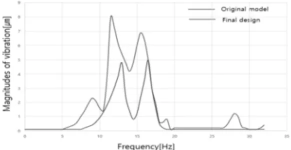
최종 개선안은 개선안 #1, #2, #3을 모두 적용한 것이며 결과는 Table 8, Fig. 13 과 같다. Table 8은 설계 개선 전.후 장 비 주요부에서 발생하는 진동량이며 주요부 진동량의 평 균 값을 비교하면 52%의 진동량이 감소된 것을 확인할 수 있다.
Table 8. Vibration magnitudes of original model and final alteration
Locations Main spindle
Ingot
holder Bobbin Load sell
Compar ison
Original [um, (%)]
3.9 (100)
4.3 (100)
4.1 (100)
4.6
(100) 100%
Alteration [um, (%)]
1.8 (46)
2.1 (49)
2.2 (54)
2.0 (43)
48%
(52%
↓)
Fig. 13은 개선 전.후 장비 전체(최대 진폭 지점) 진동량 을 비교한 그래프이며 그래프의 면적을 비교한 결과 약 50%의 진동량 감소된 것을 확인할 수 있으며 진동량 감 소 정도가 Table 8과 일치함을 알 수 있다.
Fig. 13. Vibration magnitudes of the original model and the final alteration.
4. 결 론
본 연구는 solar cell 웨이퍼용 wire saw의 진동을 분석하 여 큰 진동이 발생하는 원인을 파악하고 주물 등 전체 장 비의 주요 구조를 변경함이 없이 지지구조의 간단한 설 계 변경만으로 장비의 안정화를 실현하여 진동을 억제하 고자 하였다. 연구 내용을 요약하면 아래와 같다.
1. 주파수분석 실험과 Computer simulation을 통해 동특성을
분석하였으며 실험결과(Table 1., Fig. 3.)와 computer simulation 결과(Table 2., Fig. 5.)는 일치함을 확인하였다.
2. 장비의 진동 원인은 main spindle motor fan의 작동 속도 (29Hz)와 구조물의 고유진동수(28Hz), reel의 작동 속도 (11.7Hz)와 고유진동수(11.5Hz), reel motor의 작동 속도(21.5Hz) 와 고유진동수(18.3Hz)가 각각 공진 영역에 있어 큰 진동 을 유발하게 된다. 특히 11.5Hz의 진동이 본 장비 불안정 성의 가장 큰 문제이며 이를 개선하기 위해서 장비의 지 지구조를 개선하는 방향으로 연구를 진행 하였다.
3. 개선안은 첫째, 지지부 볼트의 지름을 30mm 에서 48mm로 변경[Fig. 10] 하였고 둘째, 지지부 높이를 60mm에 서 45mm로 줄여[Fig. 11] 강성을 강화시키고 구조물 고유 진동수와 작동 속도의 공진을 억제할 수 있는 설계 개선 안을 적용하였으며 셋째, 지지부에 보강대를 설치[Fig. 12]
하여 강성을 강화하고 고유진동수와 작동 속도의 공진을 억제하였다.
5. 최종 개선안으로 #1, #2, #3의 개선안을 동시 적용하였 으며 강성 강화와 공진 억제를 통하여 52%의 진동을 소 멸시킬 수 있음을 확인 하였다.
6. 본 연구의 결과 장비의 진동을 억제하기 위하여 주 물과 같은 장비 주요 부분의 구조 변경 없이 지지구조의 단순한 설계변경만으로 큰 진동 억제효과를 얻을 수 있 음을 확인 하였으며 이 결과는 현재 사용 중인 다양한 공 작기계 및 전용기의 진동억제에 활용될 수 있을 것으로 기대된다.
감사의 글
본 연구는 금오공과대학교 학술 연구비 지원에 의하여 연구된 논문으로 이에 관계자 여러분께 감사 드립니다.
참고문헌
1. Ro, S. H., Mechanical Vibrations with Applications, Chaos Book, pp. 22-58, 2013.
2. Shin, H. B., and Ro, S. H., “Design Alterations of a Squaring & Grinding Machine for the Solar Cell Wafer to Suppress Vibrations”, Journal of the Semiconductor
& Display Technology, Vol. 16, pp25-30, 2017.
3. Ro, S. H., Park, Y. R.,” Stability Design of a Laser Cutter for the Strengthened Glass”, Journal of the Semiconductor & Display Technology, Vol. 14, pp.19-25,
이일환 · 노승훈 · 김동욱 · 박인규 · 길사근 · 김영조 64
2015.
4. Ro, S. H., "Design Alteration of a Milling Machine Structure for the Improved Stability," Journal of the Korean Society of Manufacturing Process Engineers, Vol. 5, pp. 72-78, 2006.
5. Cho, H. J., and Ro, S. H., "Effect of Design Parameters on the Variation of Natural Frequencies of the Uniform and the Nonuniform Cantilever Beams," Transactions of the KSME, Vol. 23, pp. 697-708, 1999.
6. Yi, I. H., and Ro, S. H., “Structural Design of an Ingot Grower of the Semiconductor Wafer for the Stability Improvement”, Journal of the Semiconductor & Display
Technology, Vol. 16, No. 1, pp. 14-39, 2017.
7. Jeon, C. S., Kim, Y. G., and Kwon, H. B., "A Study on Impact Damage Characteristics of the Window Glass for High Speed Train," Journal of the Korean Society for Railway, Vol. 15, pp. 217-223, 2012.
접수일: 2018년 8월 24일, 심사일: 2018년 9월 19일, 게재확정일: 2018년 9월 19일