360 비디오의 SSP를 위한 기하학적 패딩
김 현 호
a)
, 명 상 진a)
, 윤 용 욱a)
, 김 재 곤a) ‡
Geometry Padding for Segmented Sphere Projection (SSP) in 360 Video
Hyun-Ho Kim
a)
, Sang-Jin Myeonga)
, Yong-Uk Yoona)
, and Jae-Gon Kima) ‡
요 약
360 비디오는 VR 응용의 확산과 함께 몰입형 미디어로 주목받고 있으며, JVET(Joint Video Experts Team)에서 post-HEVC로 진 행중인 VVC(Versatile Video Coding) 표준화에서 360 비디오 부호화도 함께 고려되고 있다. 360 비디오 부호화를 위하여 2D로 투영 된 영상에는 투영 면(face) 경계의 불연속성과 비활성 영역이 존재할 수 있으며 이는 부호화 효율을 저하시키고 시각적 아티팩트 (visual artifact)를 발생시킬 수 있다. 본 논문에서는 2D 투영 기법 중 SSP(Segmented Sphere Projection)에서의 이러한 불연속성과 비 활성 영역을 줄이는 효율적인 기하학적 패딩(padding) 기법을 제시한다. 실험결과, 제안 기법은 복사에 의한 패딩을 사용하는 기존
SSP 대비 미미한 부호화 효율 저하는 있지만 주관적 화질이 향상된 것을 확인할 수 있었다.
Abstract
360 video is attracting attention as immersive media, and is also considered in VVC (Versatile Video Coding), which is being developed in JVET (Joint Video Expert Team) as a new video coding standard of post-HEVC. A 2D image projected from 360 video for its compression may has discontinuities between the projected faces and inactive regions, and they may cause the visual artifacts in the reconstructed video as well as decrease of coding efficiency. In this paper, we propose a method of efficient geometric padding to reduce these discontinuities and inactive regions in the projection format of SSP (Segmented Sphere Projection). Experimental results show that the proposed method improves subjective quality compared to the existing padding of SSP that uses copy padding with minor loss of coding gain.
Keywords : Versatile Video Coding (VVC), JVET, 360 video, visual artifact, padding
Copyright Ⓒ 2016 Korean Institute of Broadcast and Media Engineers. All rights reserved.
“This is an Open-Access article distributed under the terms of the Creative Commons BY-NC-ND (http://creativecommons.org/licenses/by-nc-nd/3.0) which permits unrestricted non-commercial use, distribution, and reproduction in any medium, provided the original work is properly cited and not altered.”
a)한국항공대학교 항공전자정보공학부(Korea Aerospace University, School of Electronics and Information Engineering)
‡Corresponding Author : 김재곤(Jae-Gon Kim) E-mail: [email protected] Tel: +82-2-300-0414
ORCID: https://orcid.org/0000-0003-3686-4786
※이 논문의 연구결과 중 일부는 “한국방송·미디어공학회 2018년 추계학술대회”에서 발표한 바 있음.
※이 논문은 과학기술정보통신부의 재원으로 정보통신산업진흥원의 지원을 받아 수행된 연구임(No. 2017-0-00486).
※This work was supported by IITP grant funded by Korea Government (MSIT) (No. 2017-0-00486).
※Parts of this work have been published in the 2018 Fall Conference of the Korean Institute of Broadcasting and Media Engineers.
· Manuscript received November 9, 2018; Revised December 26, 2018; Accepted December 26, 2018.
특집논문 (Special Paper)
방송공학회논문지 제24권 제1호, 2019년 1월 (JBE Vol. 24, No. 1, January 2019) https://doi.org/10.5909/JBE.2019.24.1.25
ISSN 2287-9137 (Online) ISSN 1226-7953 (Print)
I. Introduction
In recent years, 360 videos have been attracting increased attention as a new type of media that provides an immersive experience. This type of media is captured using multi-cam- era arrays, and image stitching is applied to obtain a spher- ical representation of the scene, named 360 video. For the Joint Video Experts Team (JVET), which is developing the next generation of video coding standards with capabilities beyond High Efficiency Video Coding (HEVC) named Versatile Video Coding (VVC), 360 videos are included in the scope of the standard, along with standard dynamic range (SDR) and high dynamic range (HDR) content [1].
In general, existing video codecs are designed consider- ing conventional 2D video captured on a plane. Therefore, in the workflow of 360 video coding in JVET [2], first, the 360 videos are projected onto the 2D plane in a projec- tion format. After that, the projected 360 video is coded and reconstructed with conventional video codecs, like HM that is the HEVC reference software or JEM that is the JVET reference software. Finally, the reconstructed video is converted again to the original sphere format through format conversion. JVET established the 360Lib software package for 360 video coding and the necessary processing
[3] such as projection and defined the common test con- dition (CTC) for 360 video coding. The 360Lib software can perform projection format conversion between various projection formats as a standalone conversion tool, or in combination with HM or JEM encoding and decoding along various quality evaluation metrics.
In 360Lib, 11 projection formats are integrated for con- version between formats and further evaluation, e.g., equi- rectangular projection (ERP), cubemap projection (CMP), segmented sphere projection (SSP), etc. The currently avail- able 360 videos are provided in the ERP format. Thus, pro- jection format conversion is performed to convert the native ERP format to another format before coding is applied.
All projection formats except ERP contain more than one face, and then, the faces are packed into a 2D rectangular picture to be coded with a frame packing method. In some projection methods, a converted 2D image has inactive re- gions which are simply padded with gray color as well as discontinuities between faces. Such inactive regions and discontinuities may degrade coding efficiency and cause visual artifacts in a generated viewport which includes face boundaries. To overcome these drawbacks, various meth- ods of frame packing and padding have been proposed.
Additionally, depending on the specific projection format
그림 1. 360 비디오 부호화 프레임워크 구조[3]
Fig. 1. Framework of 360 video coding [3]
used to represent the spherical video, the same areas of the sphere at different positions are sampled at different den- sities on the 2D plane. For example, the commonly used ERP format oversamples the sphere at the poles, resulting in over-stretched top and bottom areas of the ERP picture.
Because projecting a spherical 360 video onto a 2D plane is a non-uniform mapping, the conventional peak sig- nal-to-noise ratio (PSNR), which weighs the sample errors at each 2D position equally, is not a suitable quality metric for 360 video. Therefore, 360Lib supports four spherical quality metrics for 360 video quality evaluation: weight- ed-to-spherically uniform PSNR (WS-PSNR), spherical PSNR using the nearest neighbor position without inter- polation (S-PSNR-NN), spherical PSNR with interpolation (S-PSNR-I), and PSNR in Craster’s parabolic projection format (CPP-PSNR). In order to evaluate viewport quality, viewport-based PSNR is also supported. The framework for 360 video coding and testing procedures in JVET is shown in Figure 1 [3].
As shown in Fig. 1, there is calculation of 360 video ob- jective quality metrics at different stages in the CTC coding pipeline under the following three categories. First, end-to-end (E2E) distortion measurement is calculated be- tween the original signal and the reconstructed signal, both of which are in the source projection format, namely ERP.
This considers both projection conversion errors and cod- ing errors. Second, the cross-format distortion measurement is calculated between the original signal in the source pro- jection format (ERP) and the reconstructed signal in the coding projection format. This measures projection con- version errors and coding errors. Third, the coding dis- tortion measurement which only measures coding error is calculated between the input to the codec and the output of the codec.
In this paper, efficient methods of padding around the pole region by using geometrical characteristic of 360 vid- eo is presented to reduce visual artifacts. In this way, by padding the inactive regions around the pole with highly
correlated pixels, the discontinuities between active and in- active regions are reduced.
II. Segmented Sphere Projection (SSP)
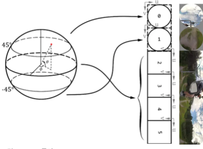
The basic SSP [4] is a typical projection in which in- active regions exist. As shown in Fig. 2, the SSP segments the sphere into three faces: north pole, equator and south pole. The boundaries of three segments are 45°N and 45°S latitude. The four corners of each pole segments are in- active samples and are filled with the default gray color.
그림 2. SSP 투영
Fig. 2. Segmented Sphere Projection (SSP)
The inactive regions may cause visual artifact as well as coding efficiency decrease due to discontinuities between active and inactive regions. To efficiently overcome these drawbacks, a padding method has been proposed in JVET [5]. In [5], as shown in Fig. 3, copy padding is applied around boundary of two pole segments and the boundary between the pole segment and the equatorial segment. In this way, the height of 2D frame is increased by 24 pixels.
The pixels in the padding region are obtained by blending
the pixels in the boundary of the circle and pixels in the
boundary of the inactive region. The weights of two pixels
to be blended are determined according to the distances to
each pixel. This padding method noticeably reduces the visual artifact and the BD-rate performance are also improved. However, instead of using copy padding, filling the padding region by more exact pixel value with the con- sideration of each location in a sphere may improve the subjective quality.
그림 3. SSP 패딩 영역[5]
Fig. 3. SSP padding regions [5]
III. Proposed SSP Geometry Padding
If the inactive regions are filled with the adjacent pixels in the given sphere video, the high correlation between ac- tive and inactive regions could be kept in the projected 2D video. However, copy padding is applied around boundary of two pole segments and the boundary between the pole segment and the equatorial segment in the conventional SSP. As shown in Fig. 1, two circles of the SSP are in contact with the four rectangular faces at the latitude of
±45° in the given sphere video. Therefore, in this paper, the inactive regions are filled with the pixels obtained on the pixels at the boundaries of corresponding rectangular
faces for padding. In other words, as shown in Fig. 4, the pixels in top and bottom lines of the equatorial regions which are adjacent to the north and south pole, re- spectively, are used to pad the corresponding inactive re- gions in the corresponding circle. Fig. 5 shows the part of the conventional SSP which is applied copy padding, and (b) is the part of the proposed SSP which is applied geome- try padding.
그림 5. 기존 SSP와 제안하는 기법이 적용된 SSP 영상의 일부 Fig. 5. Parts of 2D images of the conventional SSP and proposed SSP
For the proposed geometric padding, it is necessary to calculate where the pixel corresponding to the pixel in the padding region is located on the other faces. (1) and (2) are the equation for the proposed geometric padding. First, calculate the 3D coordinate value (Φ,θ) from the 2D coor- dinate value (m,n) by using (1). And then, using (2), the 2D coordinate value of other face corresponding to the geo- metrical padding position is calculated. The pixel values
of the calculated coordinates are used to fill each corre- sponding geometric padding location.
그림 4. 제안 SSP 기하학적 패딩을 위한 각 패딩 영역과 해당 적도 영역
Fig. 4. Padding regions and their corresponding equatorial locations in the proposed geometry padding
1
2 2
tan 0.5, 0.5
2 2
1 (1) 2
0.5 0.5
2 2
A A
m n
r A
A A
r m n
f
q p
-
ì æ ö
ï = ç - + - - ÷
ï è ø
ïï æ ö
= -
í ç ÷
è ø
ï
ï æ ö æ ö
ï = ç - + ÷ +ç - - ÷
ï è ø è ø
î
(1)
2 sin
1 0.5
2
4
(2) 2 cos
1 0.5
2
4
m A
n A
p q f
p
p q f
p
ì æ æ ö ö
ç - ÷
ï ç ÷
è ø
ï = ç + ÷-
ï ç ÷
ç ÷
ïï è ø
í æ æ ö ö
ï ç ç - ÷ ÷
ï = ç +è ø ÷-
ï ç ÷
ï ç ÷
ï è ø
î
(2)
IV. Experimental Results
The proposed method was implemented on 360Lib-5.0 [2] and HM-16.16 [6], then evaluated according to the JVET CTCs and the evaluation procedures for 360 videos [7]. The experimental results were compared with the copy padded SSP of the 360Lib software [3]. Table 1 shows the average Bjøntegaard-Delta (BD)-rate performance on the Y component in the five test sequences included in the call
for proposals, along with various quality metrics, such as E2E S-PSNR, E2E WS-PSNR.
As a result, the proposed methods obtain, in terms of E2E S-PSNR and E2E WS-PSNR, the average BD-rate loss of 0.05% and 0.08% on the Y component compared to existing SSP.
E2E WS-PSNR Y E2E SPSNR-NN Y
8K
Chairlift 0.04% 0.07%
KiteFlite 0.16% 0.04%
Harbor 0.04% -0.16%
6K Landing 0.08% 0.13%
All 0.08% 0.02%
표 1. 실험 결과(Anchor: SSP[5])
Table 1. Experimental Results (Anchor: SSP [5])
In Fig. 6 and 7, the sequence of “Landing” and “Chair- liftRide” are shown for the subjective quality comparison of the test. In Fig. 6 and Fig. 7, (a) shows a part of the reconstructed image in which visual artifacts of the SSP with copy padding are shown, and (b) shows the same part of the reconstructed image of the proposed SSP with geom- etry padding. In addition, (c) shows the viewport region on SSP. Blue circle shows the boundary between padded re-
그림 6. (a) Copy 패딩이 적용된 SSP (b) 제안 패딩 방식이 적용된 SSP (c) SSP상에서의 viewport 영역 Fig. 6. (a) SSP with copy padding (b) SSP with geometry padding (proposed) (c) Viewport region in SSP
gion and original SSP region, and the red block is the VP region of (a), (b). It is noted that the visual artifacts are reduced in the proposed method in comparison with the ex- isting SSP method.
V. Conclusions
In this paper, a geometry padding method for SSP of 360 videos is proposed to reduce visual artifacts caused by its 2D projection. The experimental results show on average 0.08% BD-rate loss on luma component over the existing SSP. However, the visual artifacts reduction can be notice- able by padding around the pole region of the SSP with the proposed methods.
참 고 문 헌 (References)
[1] J. Ohm, M. Wien, “Future Video Coding – Tools and Developments beyond HEVC,” in Proc. ICIP 2017, Oct. 2017.
[2] 360Lib, [Online]. Available at: https://jvet.hhi.fraunhofer.de/svn/svn_
360Lib/
[3] Y. Ye, E. Alshina, and J. Boyce, “Algorithm descriptions of projection format conversion and video quality metrics in 360Lib (Version 5),”
Joint Video Exploration Team of ITU-T SG16 WP3 and ISO/IEC JTC1/ SC29/WG11, JVET-H1004, 8th Meeting, Oct. 2017.
[4] C. Zhang, Y. Lu, J. Li, and Z. Wen, “AHG8: Segmented Sphere Projection for 360-degree video,” Joint Video Exploration Team of ITU-T SG16 WP3 and ISO/IEC JTC1/SC29/WG11, JVET-E0025, Jan. 2017.
[5] Y.-H. Lee, H.-C. Lin, J.-L. Lin, S.-K. Chang, C.-C. Ju, “EE4: ERP/
EAP-based segmented sphere projection with different padding sizes,”
Joint Video Exploration Team of ITU-T SG16 WP3 and ISO/IEC JTC1/SC29/WG11, JVET-G0097, Jul. 2017.
[6] HM reference software, [Online]. Available at: https://hevc.hhi.
fraunhofer.de/svn/svn_HEVCSoftware/
[7] J. Boyce, E. Alshina, and D. Zeng, “Subjective testing method for com- parison of 360 video projection formats using HEVC,” Joint Video Exploration Team of ITU-T SG16 WP3 and ISO/IEC JTC1/SC29/
WG11, JVET-F1004, Mar. 2017.
그림 7. (a) Copy 패딩이 적용된 SSP (b) 제안 패딩 방식이 적용된 SSP (c) SSP 상에서의 viewport 영역 Fig. 7. (a) SSP with copy padding (b) SSP with geometry padding (proposed) (c) Viewport region in SSP
![그림 1. 360 비디오 부호화 프레임워크 구조[3]](https://thumb-ap.123doks.com/thumbv2/123dokinfo/4787170.519988/2.892.171.732.761.1023/그림-비디오-부호화-프레임워크-구조.webp)
![Fig. 3. SSP padding regions [5]](https://thumb-ap.123doks.com/thumbv2/123dokinfo/4787170.519988/4.892.462.805.398.587/fig-ssp-padding-regions.webp)

