1.
서 론우리나라는 온실가스 감축 및 미세먼지 문제 해결을 위해 신재생에너지를 적극 활용하고자 하고 있으며, 수소는 최근 정부가 정책적으로 지원을 하고 있는 에 너지 분야이다. 관련 상위 정책 및 계획을 살펴보면 2030년 온실가스 감축 목표를 18%에서 32%로 강화하 는 국가 온실가스 감축 수정로드맵(‘18.7)과 국토와 도 시, 건물과 교통, 도로⋅항만⋅상하수도 기반시설 저탄 소 녹색성장 개편을 골자로 하는 「저탄소 녹색성장 기 본법」 이 대표적이다. 또한, 「신에너지 및 재생에너지 개발ㆍ이용ㆍ보급 촉진법」, 「수소경제 활성화 로드맵」,
「수소 기술개발 로드맵」을 기반으로 수소 에너지를 적
극 활용해 온실가스 및 미세먼지 문제에 대한 대책을 수립하고 있다1,2).
현재 수소 인프라에 대한 투자는 모빌리티와 충전 소 확충, 가정 및 건물용 수소발전 용량 증대(‘20년 2.1 GW)를 통해 도시 내 수소가 주된 에너지원으로 활용되는 수소도시 조성을 목표로 진행되고 있으며 이는 「수소도시 조성 및 운영에 관한 법률」을 통해 가속 화되고 있다. 이의 일환으로 3개의 수소 시범도시(안 산, 울산, 전주⋅완주)를 지정하고 1개의 수소 R&D 특 화도시(삼척)를 선정하여 수소생태계가 형성된 도시모 델을 만들고, 주거부분 등에서 발생하는 제약요인을 해소하기 위해 ‘수소 시범도시 인프라 기술개발’ 사업 을 진행 중이다.
***한국건설기술연구원 수소인프라클러스터 전임연구원 (Hydrogen-infra. Research Cluster, Korea Institute of Civil Engineering and Building Technology)
***한국건설기술연구원 수소인프라클러스터 수석연구원 (Hydrogen-infra. Research Cluster, Korea Institute of Civil Engineering and Building Technology)
https://doi.org/10.14346/JKOSOS.2021.36.4.71 http://www.kosos.or.kr/jkosos
주택 내 수소연료전지 전용실의 폭발 위험성에 대한 실험적 연구
박병직*⋅김양균**†⋅황인주***
An Experimental Study on the Explosion Hazards in the Fuel Cell Room of Residential House
Byoungjik Park*⋅Yangkyun Kim**†⋅Inju Hwang***
†
Corresponding Author Yangkyun Kim Tel : +82-31-369-0559
E-mail : [email protected] Received : May 24, 2021 Revised : June 24, 2021 Accepted : August 2, 2021
Abstract : In this study, a real-scale fuel-cell room of volume 1.36 m
3is constructed to confirm the explosion characteristics of hydrogen–air mixture gas in a hydrogen- powered house. A volume concentration of 40% is applied in the fuel-cell room as the worst-case scenario to examine the most severe accident possible, and two types of doors (made of plastic sheet and wood) are fabricated to observe their effects on the overpressure and impulse. The peak overpressure and impulse based on distance from the ignition source are experimentally observed and assessed. The maximum and minimum overpressures with a plastic-sheet door are about 20 and 6.7 kPa and those with a wooden door are about 46 and 13 kPa at distances of 1 and 5 m from the ignition source, respectively. The ranges of impulses for distances of 1–5 m from the ignition source are about 82–28 Pa·s with a plastic-sheet door and 101–28 Pa·s with a wooden door. The amount of damage to people, buildings, and property due to the peak overpressure and impulse is presented to determine the safe distance;
accordingly, the safe distance to prevent harm to humans is about 5 m based on the
‘injuries’ class, but the structural damage was not serious.
Key Words : hydrogen housing, deflagration, hydrogen explosion, blast wave, peak overpressure
Copyright@2021 by The Korean Society
of Safety All right reserved.
을 통해 수소를 포함한 재생 에너지를 활용해 에너지 자립률 130%를 달성하고 안전한 수소 운용에 대한 기 초자료를 마련할 계획이다. 단지 내 수소가 공급될 경 우 각 주택은 연료전지를 통해 열과 전기를 공급하게 되며, 연료전지는 기존의 보일러실과 같은 분리된 공 간 내에 환기시설을 갖추고 위치하게 된다. 연료전지 는 보일러와 다르게 가연가스인 수소가 연료전지실 내 에 직접 공급되기 때문에 위험성이 높다. 누출에 대비 한 감지 및 모니터링과 적합한 환기 시스템이 개발되 어 안전한 사용이 이루어져야 할 것이다.
수소가 연료전지실과 같은 밀폐/반밀폐된 공간 내에 서 누출이 일어날 경우 사고발생 시나리오 중 최악의 시나리오(A worst-case scenario)는 폭발이다.
최악의 시나리오는 주택 설계 및 안전이격거리 (Safety distance or separation distance) 등의 산정에 필 요하기 때문에 반드시 고려되어야 한다. Abedini3), Wesevich4), Syed5) 등은 TNT 폭발시 발생하는 압력과 충격량이 철근 콘크리트 구조체에 미치는 영향을 연구 하였으며, Grothe6), Sato7), Rolye8) 등은 수소-공기 혼합 가스의 혼합 농도별 폭발에 대해 고찰하였고, Kim9)은 수소 설비 모형의 유무에 따른 밀집도(Obstacle blockage ratio)별 폭발 실험을 통해 거리별 과압(Overpressure) 및 임펄스(Impulse)를 측정하여 인명 및 재산 피해 영향 예측에 활용 할 수 있는 자료를 제공하였다. Kashkarov10), Molkov11) 등은 수소 폭발로 발생한 폭풍파(Blast Wave) 를 계산하고, 사고 대응자가 대응에 앞서 폭발 조건에 따라 피해 영향 범위 정도를 쉽게 이해할 수 있는 노모 그램(Nomogram)을 제시하였다. Tanaka12) 등은 수소충 전소와 내부 설비의 실규모 모형을 만들어 폭발 실험 을 했고, Sommersel13) 등은 20인치 ISO 컨테이너를 대 상으로 실규모 수소폭발 실험을 수행해 산업에서 현재 이용 중인 수소 관련 실증실험을 통한 위험성 검증이 이루어졌다.
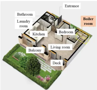
본 연구는 수소 시범도시 인프라 기술개발 사업에서 참고하는 로렌하우스의 보일러실을 수소주택 연료전 지실로 가정하여 수소폭발 위험성을 알아보았다. 화염 전파속도가 가장 빨라 폭발 압력이 높게 발생되는 수 소농도 범위 30-40% 중 40%의 수소농도를 최악의 사 고시나리오로 가정했다6). 여기서 로렌하우스 보일러실 (1.36 m2)은 Fig. 1에서 보는바와 같이 별도의 환기시설 없이 1층에 배치하고, 주택 외벽을 공유하며, 상부에는
Fig. 1. Rorenhouse 1st floor plan
14).
2층으로 올라가는 나무 계단참이 있고, 현관과 별도의 문을 이용하여 출입이 가능한 구조이다14).
2.
본 론 2.1 수소 주택 폭발 실험2.1.1 실험 이론
폭발은 급격한 에너지를 방출하며 폭풍파(Blast Wave), 비산물(Fragment, Debris), 복사열(Heat Flux), 소음을 수 반하며, 전파속도에 따라 폭굉(Detonation, 전파속도:
1,000~3,500 m/s)과 폭연(Deflagration, 전파속도: 0.1~10 m/s)으로 구분할 수 있다. 폭연은 압력면이 음속과 같 은 속도로 이동하며, 반응면이 이후에 이동하게 되어 폭굉에 비해 전파 속도가 느리다. 증기운폭발(VCE, Vapor Cloud Explosion)은 다량의 가연성 증기가 대기 중에 방출되고 공기와 혼합하여 증기구름을 형성하고 유동하다가 폭발이 가능한 농도에서 점화원을 만나 폭 발하는 현상이다15,16). 본 연구에서는 수소를 에너지원 으로 활용하는 주택의 연료전지실에서 발생하는 폭연 현상을 실규모 실험으로 확인하였다.
2.1.2 실험 준비
본 실험은 부산대학교 선박해양플랜트기술연구원의 야외실험장에서 실시되었으며, 실험 당일 외기온도는 8.4℃, 상대습도는 51.0%, 바람은 11.5 km/h(북동풍)이 였다. 철근콘크리트 구조체는 Fig. 2과 같이 실제 연료 전지실 규모(L:1,825, W:745, H:1,570 mm)로 제작(내체 적 : 2.13 ㎥)하였으며, 목재 합판문(L:900, H:1,200 mm) 을 설치하고, 내부에 고체산화물 연료전지가 배치되는
Fig. 2. Schematical description of the test specimen (Floor plan).
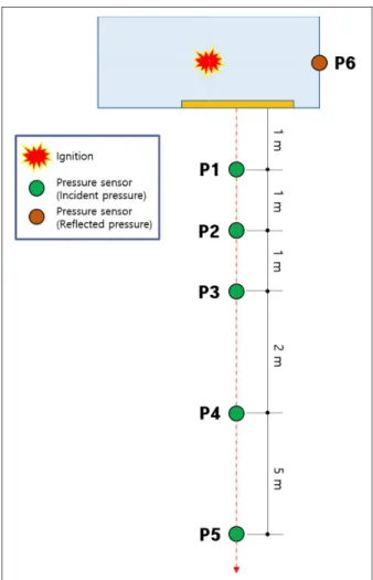
Fig. 3. Installation of the pressure sensors.
것을 가정하여 수소 설비 모형(L:600, W:500, H:1,000 mm)을 배치하였으며, 이에 따라 밀집도(Obstacle blockage ratio)는 약 14.05%가 되었다. Fig. 3과 같이 반사압 측 정센서(1 EA)는 구조체 내부(H:1,000 mm)에 배치하였 으며, 입사압 측정센서(5 EA)는 구조체의 입구를 기준 으로 일정 거리(1, 2, 3, 5, 10 m)에 설치하였다.
실험은 문틀에 실험 전용 비닐 시트를 설치한 경우 와 목재합판 문을 설치한 경우로, 총 2회 실시하였다.
(a) Structure (b) Gas supply unit
(c) Incident pressure sensor (d) Reflected pressure sensor
(e) Gas supply nozzle (f) Fan
(g) Detail for door frame (h) Hydrogen concentration sensor(Left) & Ignition(Right) Fig. 4. Details of measurement method.
Table 1. Specification of the test equipment
Equipment Characteristics
Hydrogen supply system (MFC)
- Company: MKP - Model: VIC-D145 - Flow rate: 900 lpm - Working pressure: 5 bar Dynamic data logger
- Chanel: Max. 8 [CH]
- Sampling: 1,000,000 [/s]
- Operating temperature: -5~50 [℃]
Hydrogen concentration sensor
- Company: SGX sensortech - Model: VQ600
Pressure sensor
* Pressure sensor(Incident pressure) - Company: PCB PIEZOTRONICS - Model: 113B27
- Measurement Range: 100 [psi]
(Max. Pressure 1 [kpsi]) - Sensitivity: 50 [mV/psi]
* Pressure sensor(Reflected pressure) - Company: Dytran Instruments, Inc.
- Model: 2200V1
- Measurement Range: 100 [psi]
(Max. Pressure 1 [kpsi])
- Sensitivity: 50 [mV/psi]
체 내부의 수소-공기 혼합비율(40%)을 맞추도록 설계 하였으며, 수소농도 센서(Hydrogen concentration sensor) 와 점화기(Ignitor)을 구조체 중앙에 배치하고 수소 농 도가 적정 범위(오차율 ±3%)안에 들어오면 수소 공급 을 차단하고 점화하였다. 점화 후 즉시 폭발이 발생하 였으며, 데이터로거에 연결된 압력센서를 이용하여 입 사압(Incident Pressure)과 반사압(Reflected Pressure)을 시간(Microsecond : 100만 분의 1초) 단위로 측정하였다.
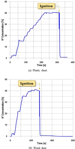
Fig. 5는 텐트 내부 수소 공급시간에 따른 수소 함량을 나타낸다. 텐트 내부에 목적하는 수소 함량인 40%를 맞 추기 위해 약 170~230초 동안 수소를 공급하였고, 약 90 초 동안 유동을 안정화 시킨 후 점화가 이루어졌다.
(a) Plastic sheet
(b) Wood door Fig. 5. Hydrogen concentration curve.
구조체 입구에서 가장 가까운 압력계(P1)에 걸리게 되 어 Fig. 7(a)에서 보는바와 같이 0.017초 이후의 P1 그 래프 형상이 다른 그래프와는 다르게 압력변화 차이가 크게 측정되었다. 최대 과압(Peak pressure)은 구조체 입구로부터 1 m에서 19.6 kPa(P1), 2 m에서 15 kPa(P2), 3 m에서 10.8 kPa(P3), 5 m에서 6.7 kPa(P4)이 측정되었 으며, 10 m 거리에서는 유의미한 데이터를 측정하지 못하였다.
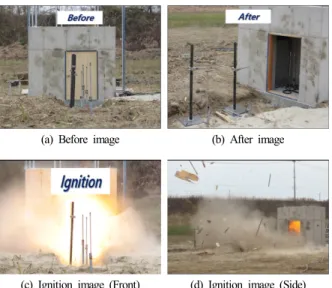
목재합판 문을 사용한 두 번째 실험에서는 Fig. 7과 같이 점화원으로 부터 전파된 화염의 길이가 육안으로 약 1 m가 측정되었으며, 먼지 폭풍이 약 5 m 관측되었 다. 폭발하면서 목재합판문의 일부가 구조체 입구에서 가장 가까운 압력계(P´1)에 충격을 가하게 되어 Fig.
8(b)에서 보는바와 같이 0.017초 이후의 P´1 그래프 형 상이 다른 그래프와는 다르게 변동폭이 크게 측정되었 으며, 목재합판 문은 폭발과 동시에 약 100 여개(30 cm2 미만)의 파편(Fragment)이 비산하였다. 파편의 비 산거리는 나무판(Plate)은 35 m, 나무틀(Frame)은 20 m, 힌지(Hinge)는 12 m가 측정되었다. 최대 과압은 구조체 입구로부터 1 m에서 46.7 kPa(P´1), 2 m에서 48.6 kPa (P´2), 3 m에서 27.5 kPa(P´3), 5 m에서 13.8 kPa(P´4)이 측정되었으며, 첫 번째 실험과 유사하게 10 m 거리에 서는 유의미한 데이터를 측정하지 못하였다. 여기서 P1의 입사압력이 P2보다 낮게 측정되었는데, 이는 폭 발 순간 나무문의 영향으로 사료된다.
(a) Before ignition (b) After ignitnion
(c) Ignition image (Front) (d) Ignition image (Side)
Fig. 6. High-speed video frames from deflagration with plastic
sheet door.
(a) Before image (b) After image
(c) Ignition image (Front) (d) Ignition image (Side) Fig. 7. High-speed video frames from deflagration with wooden door.
(a) Plastic sheet door
(b) Wooden door Fig. 8. Incident Pressure with respect to time.
Fig. 9. Reflected Pressure with respect to time.
Fig. 9은 시간에 따른 내부의 반사압을 나타낸다. 비 닐 시트는 수소-공기 혼합 가스를 내부에 가둬두는 역 할만 할 뿐 압력에는 미미한 영향을 미쳐 내부의 반사 압력(16.5 kPa(P6))과 외부 1 m 지점의 최대 입사압 (19.7 kPa(P1))의 차이가 크지 않았다. 하지만 두 번째 실험의 경우는 문이 압력팽창을 일정시간 지연시켜주 기 때문에 반사압이 입사압 최대값(P´2)보다 24.3 kPa 큰 70.9 kPa(P´6)으로 측정되었다15).
임펄스은 지속시간 동안 작용한 압력 값들의 총합이 므로 적분 함수를 사용하여 과압-시간 그래프에서 곡 선 아래의 면적으로 구할 수 있다17).
(1)
: Ambient pressure [Pa]
: Incident overpressure [Pa]
: Arrival time [s]
: Duration of positive phase [s]
: Specific impulse of positive phase [Pa·s]첫 번째 실험에서의 임펄스 값(
)은 P1에서 82 Pa·s, P2에서 58 Pa·s, P3에서 40 Pa·s, P4에서 28 Pa·s, P6에서 161 Pa·s이며, 두 번째 실험에서의 임펄스 값(
)은 P´1 에서 101 Pa·s, P´2에서 74 Pa·s, P´3에서 52 Pa·s, P´4에 서 28 Pa·s, P´6에서 626 Pa·s으로 계산되었다.2.2 수소 주택 폭발실험 결과 해석
압력상승속도와 지속시간은 폭발로 인한 피해 규모 를 산정하는데 중요한 지표가 되며, 정압(Positive phase)
∆
·
(2)
(3)여기서
는 입사 폭풍 과압,∆
는 폭발 중심으로 부터의 환산 입사 폭풍 과압(무차원),
는 대기압,
는 방출 에너지[J],
는 음속[m/s]을 나타낸다.TNO(Netherlands Organization for Applied Scientific Research) MEM(Multi Energy Method)는 밀폐 공간의 부피를 통해서 과압을 결정하기 때문에 여러 VCE 압 력 영향산정 모델 중 밀폐된 가연지역 내 폭발의 영향 에 관한 예측이 가능하다.
Fig. 10는 TNO MEM의 환산 거리별 환산 최대 과압 을 보여주며, Table 2는 점화에너지(Ignition energy), 밀 집정도(Obstruction), 밀폐정도(Confinement)에 따른 폭 발 강도를 나타낸다. 여기서 첫 번째 실험(플라스틱 시 트)의 조건인 높은 점화에너지, 낮은 장애물 밀집도, 개방된 공간을 고려했을때 폭발 강도 레벨은 5에 해당 하며, 예상 압력 범위는 10~50 kPa이다. 두 번째 실험 (목재합판 문) 조건인 높은 점화에너지, 낮은 장애물 밀집도, 밀폐된 공간을 고려했을 때 폭발 강도 레벨은 4에 해당하며, 예상 압력 범위는 20~50 kPa이다.
첫 번째 실험에서의 환산거리(R´)별 환산압력(Ps´)은 0.080에서 0.194, 0.112에서 0.148, 0.144에서 0.107,
Fig. 10. Scaled peak side-on overpressure(Ps’) versus scaled distance(R’) from TNO Multi-Energy model
19).
1 ○ ○ ○ 7-10 100~1000
2 ○ ○ ○ 7-10 100~1000
3 ○ ○ ○ 5-7 20~100
4 ○ ○ ○ 5-7 20~50
5 ○ ○ ○ 4-6 10~50
6 ○ ○ ○ 4-6 10~50
7 ○ ○ ○ 4-5 10~20
8 ○ ○ ○ 4-5 10~20
9 ○ ○ ○ 3-5 5~20
10 ○ ○ ○ 2-3 2~5
11 ○ ○ ○ 1-2 1~2
12 ○ ○ ○ 1 1
Fig. 11. Scaled overpressure versus scaled distance (Blue colors : plastic sheet door, Red colors : wooden door).
0.209에서 0.067이며, 두 번째 실험에서의 환산거리별 환산압력은 0.084에서 0.460, 0.117에서 0.480, 0.151에 서 0.271, 0.218에서 0.136이다. 본 연구의 실험결과 데 이터를 TNO MEM(Fig. 10)에서 환산거리를 0.1까지 확 장하여 적용하면 폭발 강도 3~6 레벨 범위에서 Fig. 11 과 같이 나타낼 수 있다. 점화원까지 거리가 기존 실험 값에 비해 상대적으로 가깝기 때문에 환산거리가 낮게 계산되어 TNO MEM에서 예상하는 환산거리별 환산 최대 압력값과 차이가 발생하였다.
폭발은 폭풍과압과 비산물을 발생하여 사람과 건물 에 피해를 준다. 인체에 미치는 직접적인 폭풍피해는 폐출혈과 고막파열이 있다. 간접적인 폭풍피해는 폭풍 파에 의해 몸 전체의 변위가 발생하여 단단한 물체와 충돌하는 경우와 폭발원이 직접 비산하여 피해를 입히
거나 폭풍파를 받은 주변의 물체가 비산하여 피해를 입히는 경우이다20).
폭풍파로 인한 폐출혈로 인한 신체피해는 압력과 임 펄스로 표현이 가능하며, 환산압력과 환산임펄스는 아 래와 같다.
는 입사 폭풍 과압,∆
는 폭발 중심으 로부터의 환산 입사 폭풍 과압,
는 대기압,
는 정압 지속시간,
는 폭발 중심으로부터의 환산 정압 지속시 간,
는 연소 에너지,
는 음속을 나타내며 Fig. 12(a) 그래프처럼 표현이 가능하다. 고막은 인간의 매우 예 민하고 복잡한 조직으로서 최대과압에 대한 고막 파열 확률은 영향을 받는 시간은 상관없이 최대과압만 고려 하고 있다15,17).
(4)
×
(5)Table 3에서는 기존 문헌들을 통해서 압력에 따른 인 적 피해 수준을 나타내고 있다. 일시적 이명 현상(TTS:
Temporary Threshold Shift)이 발생하지 않는 거리를 안 전거리라고 할 수 있으며, Baker는 1.35 kPa과 1 Pa·s 값 을 임계값(Threshold)으로 정의하였다21). 4.5 kg 이상의 물체가 비산하여 날아오다가 머리에 부딪치는 경우에 는 속도에 따라서 3.05 m/s 까지는 안전하지만 3.96 m/s 가 임계값이며, 5.49 m/s이상의 경우에는 50% 확률로 사망하며, 7.01 m/s이상의 경우에는 100% 확률로 사망
Table 3. Effects on people from blast waves Incident pressure
(kPa) Damage level
13.8 Eardrum rupture threshold
23)16.5 1% eardrum rupture probability
24,25)23 1% eardrum rupture
26)25 ~ 35 1% fatality probability
27)34.5 ~ 48.3 50% eardrum rupture probability
23)35 15% fatality probability
26)50 ~ 100 50% fatality probability
26)55.16 Lethal head injury
17,28)55.2 ~ 110.3 Standing people are thrown by distance
23)68.9 ~ 103.4 90% eardrum rupture probability
23)82.7 ~ 103.4 Lung haemorrhage threshold
23)84 90% eardrum rupture probability
24,25)100 1% fatality probability (lung haemorrhage)
24,25)140 50% fatality probability (lung haemorrhage)
24,25)200 99% fatality probability (lung haemorrhage)
24,25)한다. 몸 전체가 받는 폭풍파의 경우에는 속도에 따라 서 3.05 m/s 까지는 안전하지만 6.40 m/s가 임계값이며, 16.46 m/s이상의 경우에는 50% 확률로 사망하고, 42.06 m/s이상의 경우에는 100% 확률로 사망한다22). 16.5 kPa 보다 높은 폭풍파를 사람이 입은 경우에 고막파열로 인한 인적 피해가 발생 할 수 있으며, 100 kPa 이상의 폭풍파를 받은 경우에는 폐출혈이 발생할 수 있기 때 문에 심각한 인적 피해가 발생할 수 있다17,22).
Table 4에서는 기존 문헌들을 통해서 압력에 따른 건물 및 재산 피해 수준을 나타내고 있다. 영향 수준은
Table 4. Effects on buildings and structures from blast waves
17)Incident Pressure
(kPa) Damage Level
0.15 Annoying noise
0.2 Occasional breaking of large window panes already under strain
0.3 Loud noise; sonic boom glass failure 0.7 Breakage of small windows under strain
1 Threshold for glass breakage
2 ‘Safe distance’, probability of 0.95 of no serious damage beyond this value; some damage to house ceilings; 10%
window glass broken 3 Limited minor structural damage
3.5 ~ 7 Large and small windows usually shattered; occasional damage to window frames
5 Minor damage to house structures
8 Partial demolition to houses, made uninhabitable 7 ~ 15
Corrugated asbestos chattered. Corrugated steel or aluminum panels fastenings fail, followed by buckling;
wood panel (standard housing) fastenings fail; panels blown in
10 Steel frame of clad building slightly distorted 15 Partial collapse of walls and roofs of houses 15 ~ 20 Concrete or cinderblock walls, not reinforced, shattered
18 Lower limit of serious structural damage 50% destruction of brickwork of houses
20 Heavy machines in industrial buildings suffered little damage; steel frame building distorted and pulled away from foundations
20 ~ 28 Frameless, self-framing steel panel building demolished;
rupture of oil storage tanks
30 Cladding of light industrial buildings ruptured 35 Wooden utility poled snapped; tall hydraulic press in
building slightly damaged
35 ~ 50 Nearly complete destruction of houses 50 Loaded tank cars overturned
50 ~ 55 Unreinforced brick panels, 25~35 cm thick, fail by shearing or flexure
60 Loaded train boxcars completely demolished 70 Probable total destruction of buildings; heavy machine
tools moved and badly damaged
에 해당하며, 3.5 kPa를 초과하는 경우에는 ‘작은 피해 (Light damage)’에 해당한다17).
본 연구에서 측정된 최대 과압과 임펄스값을 기존 문헌에 의해서 인적 피해와 건물 및 재산 피해 수준을 그래프 상에 표현하면 Fig. 12와 같다. 최대 과압만을 고려했을 때는 50% 확률로 고막이 파열(34.5~48.3 kPa) 되고 집이 거의 붕괴되는 수준(35~50 kPa)의 영향이 예 상되어 건물에 ‘심각한 피해(Severe damage)’가 예상되 지만 임펄스 값이 최대 101 Pa·s(P´1)으로 낮게 측정되 었기 때문에 ‘부상(Injury)’정도의 인적 피해가 발생하
(a) harm criteria for humans
10)(b) damage for buildings
22)Fig. 12. Overpressure-impulse thresholds
(Blue colors : plastic sheet door, Red colors : wooden door).
3.
결론 및 고찰본 연구에서는 주택 내 수소연료전지 전용실을 대상 으로 실규모 폭발실험이 수행되었다. 사고 시나리오는 발생 가능한 최악의 시나리오인 수소 농도 40%의 폭 발을 가정하여 이루어졌다. 총 2건의 실험을 통해 점화 원으로부터 떨어진 거리별(1~5 m) 최대 과압 및 임펄 스가 측정되었다. 실험결과 사람에 대한 상해는 ‘부상 (Injury)’ 정도의 인적 피해가 발생하였고, 건축물에 대 한 영향은 ‘미비한 건물 피해(Minor structural damage)’
보다 낮은 정도가 발생했다.
최악의 사고시나리오 1건에 대한 실험만 수행되어 다른 조건의 시나리오에 대한 검토가 추가로 이루어져 야 할 것으로 사료되며 실제 주택의 수소연료전지실 설 계에 직접적인 반영이 가능한 안전이격거리(Separation distance)가 추가로 제시될 계획이다.
Acknowledgement: 본 연구는 국토교통부/국토교통과 학기술진흥원의 지원을 받아 수행되었습니다(과제번 호:21HSCT-B157909-02). 실험 장소 및 수행에 도움을 주신 부산대학교 선박해양플랜트기술연구원 연구진께 감사드립니다.
This work is supported by the Korea Agency for Infrastructure Technology Advancement(KAIA) grant funded by the Ministry of Land, Infrastructure and Transport (Grant 21HSCT-B157909-02). We are grateful to those who helped to conduct the experiment at the Korea Ship and Offshore Research Institute in Pusan National University.
References
1) J. O. Abe, A. P. I. Popoola, E. Ajenifuja and O. M. Popoola,
“Hydrogen Energy, Economy and Storage: Review and Recommendation”, Int. J. Hydrogen Energy, Vol. 44, pp.
15072-15086, 2019.
2) U. Sahaym, and M. G. Norton, “Advances in the Application of Nanotechnology in Enabling a Hydrogen Economy”, J. Mater. Sci., Vol. 43, pp. 5395-5429, 2008.
3) M. Abedini, A. A. Mutalib, S. N. Raman1, R. Alipour and E. Akhlagh, “Pressure–Impulse (P–I) Diagrams for Reinforced Concrete (RC) Structures”, Archives of
Computational Methods in Engineering, Vol. 26, pp.
733-767, 2019.
4) J. W. Wesevich and C. J. Oswal, “Empirical Based Concrete Masonry Pressure-Impulse Diagrams for Varying Degrees of Damage”, Baker Engineering and Risk Consultants, ASCE Structures Congress, 2005.
5) Z. I. Syed, P. Mendis, Nelson T. K. Lam and T. Ngo,
“Concrete Damage Assessment for Blast Load using Pressure-impulse Diagrams”, Earthquake Engineering in Australia, 2006.
6) M. Groethe, E. Merilo, J. Colton, S. Chiba, Y. Sato and H.
Iwabuchi, “Large-scale Hydrogen Deglagrations and Detonations”, International Journal of Hydrogen Energy, Vol. 32, No. 13, pp. 2025-2133, 2007.
7) Y. Sato, H. Iwabuchi, M. Groethe, E. Merilo and S. Chiba,
“Experiments on Hydrogen Deflagration”, J. Power Sources, Vol. 159, No. 1, pp. 144-148, 2006.
8) M. Royle, L. C. Shirvil and T. A. Roberts, “Vapour Cloud Explosions from the Ignition of Methane/Hydrogen/Air Mixtures in a Congested Region”, Proceedings of the 2nd ICHS Conference, San Sebastian, Spain, 2007.
9) Y. G. Kim and B. J. Park, “Experimental and Analytical Study on Hydrogen-air Deflagrations in Open Atmosphere”, J. Korean Soc. Saf., Vol. 36, No. 1, pp. 64-71, 2021.
10) S. Kashkarov, Z. Li and V. Molkov, “Blast Wave from a Hydrogen Tank Rupture in a Fire in the Open: Hazard Distance Nomograms”, International Journal of Hydrogen Energy, Vol. 45, pp. 2429-2446, 2020.
11) V. Molkov and S. Kashkarov, “Blast Wave from a High- pressure Gas Tank in a Fire: Stand-alone and under-vehicle Hydrogen Tanks”, International Journal of Hydrogen Energy, Vol. 40, pp. 12581-12603, 2015.
12) T. Tanaka, T. Azuma, J. A. Evans, P. M. Cronin, D. M.
Johnson and R. P. Cleaver, “Experimental Study on Hydrogen Explosions in a Full-scale Hydrogen Filling Station Model”, International Journal of Hydrogen Energy, Vol. 32, pp. 2162-2170, 2007.
13) O. K. Sommersel, K. Vaagsaether and D. Bjerketvedt,
“Hydrogen Explosions in 20’ ISO Container”, International Journal of Hydrogen Energy, Vol. 42, pp. 7740-7748, 2017.
14) www.rorenhouse.co.kr
15) D. A. Crowl and J. F. Louvar, “Chemical Process Safety Fundamentals with Applications(Fourth Edition)”, Pearson Education Inc, pp. 264-282, 2019.
16) Center for Chemical Process Safety of the American Institute of Chemical Engineers, “Guidelines for Chemical Process Quantitative Risk Analysis(Second Edition)”, A John wiley & sons Inc, pp. 157-179, 2000.
17) Center for Chemical Process Safety of the American Institute of Chemical Engineers, “Guidelines for Evaluating the Characteristics of Vapor Cloud Explosions, Flash Fires, and BLEVEs”, American Institute of Chemical Engineers, pp. 347-357, 1994.
18) V. J. Clancey, “Diagnostic Features of Explosion Damage”, 6th International Meeting of Forensic Sciences, 1972.
19) W. P. M. Mercx and A. C. van den Berg, “Methods for the Calculation of Physical Effects (The Yellow book)”, TNO, 2005.
20) G. Solomos, M. Larcher, G. Valsamos, V. Karlos and F.
Casadei, “A Survey of Computational Models for Blast Induced Human Injuries for Security and Defence Applications”, JRC(Joint Research Centre) Technical Reports, 2020.
21) W. E. Baker, P. A. Cox, P. S. Westine, J. J. Kulesz and R. A.
Strehlow, “Explosion Hazards and Evaluation”, Elsevier Scientific Publishing Company, 1983.
22) J. Debroey, “Probit Function Analysis of Blast Effects on Human Beings”, Royal Military Academy, 2016.
23) R. M. Jeffries, L. Gould, D. Anastasiou and A. P. Franks,
“Derivation of Fatality Probability Function for Occupants Buildings Subject to Blast Loads”, Probabilistic Safety Assessment and Management, pp. 669-675, 1996.
24) S. Mannan, “Lees’ Loss Prevention in the Process Industries”, Elsevier Butterworth-Heinemann, Vol. 1, 2005.
25) L. E. Fugelso, L. M. Weiner and T. H. Schiffman,
“Explosion Effects Computation aids”, Gen Am Div Gen Am Transportation Co Niles Illinois US GARD, 1972.
26) NFPA, “NFPA 2 Hydrogen Technologies Code” pp.
02169-7471, 2020.
27) Health and Safety Executive, “Methods of Approximation and Determination of Human Vulnerability for Offshore Major Accident Hazard Assessment”, Supporting Document to SPC, Vol. 30, 2010.
28) Center for Chemical Process Safety to the American Institute of Chemical Engineers, “Guidance for Consequence Analysis of Chemical Releases”, American Institute of Chemical Engineers, 1999.