H-커플링 슬롯 광대역 이중편파 마이크로스트립 안테나
1)김 장 욱*, 전 주 성**
Wideband Dual-polarized Microstrip Antenna with H-shaped Coupling Slot
Jang Wook Kim*, Joo Seong Jeon**
요 약
본 논문에서는 H-형 커플링 슬롯을 가진 광대역 이중 편파 마이크로스트립 안테나를 제안하였다. 제안된 안테나는 통신사업자들이 경쟁적으로 공공장소에 구축하고 있는 hot-spot zone과 같은 제한된 장소에서 많 은 통신 단말기가 동시에 사용되면 상호 간섭이나 다중경로 페이딩에 의한 전송품질의 열화 발생을 방지할 수 있다. 설계된 안테나는 2.7GHz 이하의 주파수 대역에서 33.98%의 임피던스 대역폭(SWR ≤ 2)과 8.58 dBi (at 2.11 GHz)의 최대 이득을 갖는 것을 측정결과를 통하여 확인하였다. 제안된 안테나는 단순 한 구조로 다중 주파수 대역을 수용할 수 있으며 다양한 상업적인 적용이 가능하도록 대량생산의 장점을 갖 는다.
▸Keywords : 마이크로스트립, 에이치-쉐이프드, 브로드밴드, 안테나, 모바일
Abstract
This paper investigates wideband dual-polarized microstrip antenna with H-shaped coupling slot. These types of antennas are used to prevent deterioration of transmission quality caused by terminal interference or multipath fading, which usually occur when many terminals are used in limited space such as hot-spot zones. The experimental results show that the impedance bandwidth (SWR ≤ 2) of 33.98% and the peak gain of 8.58 dBi (at 2.11 GHz) were obtained by the frequency band under 2.7 GHz. The proposed antenna is designed originally for multiple service bands with simple structure and easily be mass-produced for
∙제1저자 : 김장욱 ∙교신저자 : 전주성
∙투고일 : 2014. 02. 20, 심사일 : 2014. 03. 10, 게재확정일 : 2014. 03. 27.
* 동양미래대학교 정보전자과(Dept. of Information Electronics, Dongyang Mirae University)
** 한국통신 IT 부문(IT Section, Korea Telecommunication)
※ 본 논문은 동양미래대학교의 학술연구과제를 통해 연구되었음을 알립니다.
various commercial applications.
▸Keywords : Microstrip, H-shaped, Broadband, Antenna, Mobile
I. Introduction
The world telecommunication market has changed focus to the data transfer service from the voice service due to the increasing demand for internet and multimedia fields and rapid development of technology. Recently, frequencies of the mobile communication service have become higher and higher its service has changed to a wideband telecommunication as focus has changed to internet and multimedia services from narrow band communications.
Recent researches show that telecom operators use various frequency bands for serving varieties of communication methods. As a result, frequency reuse of running cell site is one of the main concerns for engineering next generation wireless communication networks. This paper suggests wideband dual -polarized microstrip antenna with H-shaped coupling slot to solve limited cell site installation space and overlaid wireless frequency environment in the urban areas.
Telecom operators are competitively building hot-spot zones for public places to vitalize convergence service. The following are two major problems from the continuous increase of hot-spot zones.
One of the main problems is antenna installation.
Installing a multiple antenna causes space shortage, interior degradation and increasing installation expenses. One solution to this problem is designing a wideband antenna that accommodates multiple frequency bands.
That is, we need a multiple band antenna that covers PCS frequency band (1,850~1,990 MHz/Band class 1), IMT-2000 frequency band (1,920~2,170 MHz), WLAN frequency band (2,400~2,480 MHz) and WiMAX frequency band (2.3~2.4 GHz, 2.469~2.690 GHz).
Another problem is the deterioration of transmission quality caused by terminal interference or multipath fading that usually occurs when multiple terminals are used in the same space and at the same time. This problem occurs especially when WLAN is used and can be resolved by using some specific techniques. Among these techniques reported so far, the polarization diversity technique is very effective for convergence services.
Polarization diversity provides the same performance of two antennas with one antenna, and thus it is a space-efficient and cost-effective way.
This study investigates wideband dual-polarized microstrip antenna with H-shaped coupling slot to resolve the two problems mentioned above. The main purpose of the study is to design dual-polarized antennas that cover multiple bands (PCS, IMT-2000,WLAN and WiMAX). In addition, we made it easy for its commercial applications by designing the air-microstrip structure, which does not use a dielectric substrate.
Ⅱ. Feed Structures for Wideband Dual-polarized Microstrip Antennas
The coaxial feed is the most widely used
technique for the microstrip antenna due to the
simple structure. This technique physically joins the
probe on a conduction face of the patch, so that the impedance matching is easy, but it has a defect of narrow impedance bandwidth. In general, the coaxial feed has several drawbacks ; an array design is not easy, the parasitic reactance is increased by the length of the probe when thick substrate is used, and the radiation characteristics of the antenna become inefficient due to the surface wave excitation.
Most researches on microstrip antennas have been focused on methods to extend the bandwidth. It has been reported in the literature in which the broadband characteristics can be obtained by improving the feeding mechanism of microstrip antennas [1]. Therefore, in this paper, a feeding mechanism is applied that is capable of making wideband by means of reducing the parasitic reactance from the feed structure of the microstrip antenna. We propose a new feeding technique for microstrip antennas that uses a pair of L-feeders and H-shaped coupling slot feeding mechanism on a single patch as shown in Fig. 1.
The wideband operation with an L-feeder is as follows [2]. The antenna proposed in this study includes the inductance (Lc) introduced by the vertical part of L-strip feeder and the capacitance (Cc) between the patch and the horizontal part of L-strip feeder. In other words, the parameters arising from the feeding mechanism are represented by the series Lc-Cc resonant circuit. On the other hand, the equivalent circuit of the patch is represented by the parallel R-L-C resonant circuit as a typical microstrip antenna.
Therefore, the series Lc-Cc resonant circuit of the feeding mechanism and the parallel R-L-C resonant circuit act as though they are connected by a serial connection. Consequently, the bandwidth performance of the antenna is improved by the second resonance caused by the Lc-Cc parameter near the main resonance in the patch. It is interesting to note that although the parameter values of Lc and Cc in the feeding mechanism are somewhat limited in the single L-strip feeder, they are working much more effectively
when a pair of L-strip feeders is used. That is, the inductance and capacitance brought about by using a pair of L-strip feeders make it possible to obtain wide bandwidth characteristics which can more closely approximate the resonant frequency of the TM01 mode of the patch.
(a)
(b)
(c)
Fig. 1 Geometry of the proposed antenna.(d)
Fig. 1 shows the proposed geometry of radiating element. The dimensions of feeding mechanism that consists of the patch and a pair of L-strip feeders are optimized by using the HFSS TM [3].
The patch, made of thin metal plate of 0.3 mm, is supported by the non-metallic post for each of the four edges. The patch is designed to operate at the center frequency (fo=1.96 GHz) of PCS and IMT-2000 service bands, and the width and length are Wp=66.1 mm (0.432λo) and Lp=52 mm (0.342 λo) respectively. The antenna’s ground plane has dimensions of 250x250mm. The ground plane dimensions are a crucial parameter in dual-polarized patch antenna designs [4]. The air-gap, the distance between the patch and the ground plane, is H=18.5 mm (0.121λo). The patch does not contribute to the bandwidth performance of the antenna. However, it does contribute to patch size reducing. Since the proposed antenna uses a pair of L-strip feeders, the feeding mechanism is complicated. That is why the size reduction of the radiating patch is a prerequisite for the antenna design. If the patch size of the antenna cannot be reduced, it can be a limiting factor in designing an array.
The feeding mechanism material of the antenna is made of thin metal plate of 0.3 mm and consists of a pair of L-strip feeders, and the feedline has the structure of what is called an air-gap feedline which does not contain a dielectric substrate. The input and output of feeding mechanism, that is, the feedline (W1) and a pair of L-strip feeders (W3), are designed to match 50Ω. Since the feedline (W1) is connected to the 50Ω SMA connector, it is designed
for the air-microstrip feedline W1=4.8 mm (50Ω) and the distance from the ground plane t=1 mm (not included the metal thickness of feedline and ground plane). The air-microstrip feedline (W1) has a through hole, and the constant height (t) between the feedline and the ground plane is maintained by using the plastic washer and the screw. The symmetrical power divider with a quarter-wave transformer, L1=L2=36.72 mm (0.24λo) and W2=3.1 mm (0.02λo), is installed in the area between the feedline (W1) and a pair of L-strip feeders. The vertical and horizontal length of the L-strip feeders are h1=7.1 mm (0.046λo) and Df=28.1 mm (0.184λo), respectively. And, the distance between the two L-strip feeders is S1=26.4 mm (0.172λo).
H-shaped coupling slot is another type of electro-magnetically coupled feed that is studied in this paper. It is a feeding mechanism where electromagnetic flux from the feedline is concentrated on the H-shaped coupling slot, which is passed to a patch. This type of feeding generates unwanted radiation by the feedline. The location of the feedline, however, can be directed in an opposite direction by the ground plane and isolated and thus the radiation pattern of the antenna is not affected much.
The structure of the microstrip antenna is
illustrated in Fig. 1. It shows that the feedline of
port 1 passes equal magnitude and phase to a pair of
L-feeders and coupled to the patch while the other
feedline of port 2 is coupled to the patch through the
H-shaped coupling slot. In this structure, the choice
of the feedlines (port 1 or port 2) operates as an
antenna for vertical polarization (E V ) and horizontal
polarization (E H ). To obtain characteristics of wide
impedance bandwidth and low cross polarization, the
H-shaped coupling slot is located at the center of
the patch, and the L-feeders are located
symmetrically with reference to the H-shaped
coupling slot, which reduces coupling with the
H-shaped coupling slot and inhibits odd-mode
Fig. 2 H-shaped coupling slot's width variable S
2
and frequency response characteristics.excitation. The two feeding mechanisms are integrated but they operate independently as vertical polarization (E V ) and horizontal polarization (E H ) antennas.
The relevant width of the H-shaped coupling slot are 0.1~0.2λo. Other important parameters for these feeding mechanism antennas are H-shaped coupling slot width (S 2 ) and slot width (S w ). The slot width (S w ) is an important parameter to reduce the antenna's back radiation [4]. Optimal characteristics for the parameters are
S2 ≥ Wf + n × t (1)
Where, n≥6
Sw = 0.1 × S2 (2)
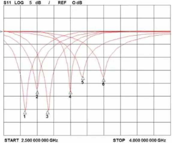
To find important parameters that maximized coupling energy in H-shaped coupling slot antenna feeding mechanism, we use various variables such as H-slot parameter S2, SL and air-microstrip feedline (port 2) Sf. In the simulation results of Fig. 2, Fig.
3 and Fig. 4 show frequency characteristics of different variables. We select center frequency fo=2.55 GHz for WLAN and WiMAX frequency bands.
We use the same parameters such as patch width,
length, ground plane and a pair of L-feeders’
dimension as previously described. The length (S L ) of H-shaped coupling slot is 34 mm and the overlapped length (S f ) between the air-microstrip feedline (port 2) and the patch antenna is 35 mm.
With these fixed parameters, we use H-shaped coupling slot width variable S 2 to find frequency characteristics.
Fig. 2 shows frequency characteristics where H-shaped coupling slot width variables (S 2 ) are 14 mm (marker 1), 12 mm (marker 2), 10 mm (marker 3), 8 mm (marker 4) and 6 mm (marker 5) respectively. The result indicates that resonant frequency decreases when S 2 parameter increases.
In the simulation result Fig. 3, we use the same parameters such as the patch width, length, ground plane and a pair of L-feeders’ dimension as previously described. H-shaped coupling slot width variable S 2 is 12 mm. Fig. 3 shows frequency characteristics where H-shaped coupling slot length variables (S L ) are 30 mm (marker 1), 28 mm (marker 2), 27 mm (marker 3), 24 mm (marker 4), 22 mm (marker 5) and 20 mm (marker 6) respectively. Similar to the previous simulation result, resonant frequency decreases when SL parameter increases.
Fig. 3 H-shaped coupling slot's length variable S
L
and frequency response characteristics.In the simulation result Fig. 4, we use the same parameters such as the patch width, length, ground plane and a pair of L-feeders’ dimension as previously described. The H-shaped coupling slot width variable S2 is 10 mm and length variable (S L ) is 34 mm. Fig. 3 shows frequency characteristics where air-microstrip feedline (port 2) length variables (Sf) are 50 mm (marker 1), 45 mm (marker 2), 40 mm (marker 3) and 35 mm (marker 4) respectively. The simulation result shows that resonant frequency and bandwidth change sensitively depend on parameter S f . Fig. 4 proves the length parameter S f =35 mm is the optimal select for frequency response.
Fig. 4 H-shaped coupling slot and air-microstrip feedline (port 2)'s length variable S
f
and frequency responsecharacteristics.
Ⅲ. Measurement Results and Discussion
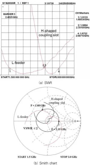
Figure 5 shows the measurements of the SWR and the impedance plot of the proposed antenna.
(a) SWR
(b) Smith chart
Fig. 5 Measured SWR and Smith chart.
The measurements of the SWR, the impedance plot of the microstrip antennas with a pair of L-feeders (port 1) and that with an H-shaped coupling slot (port 2) are shown in Fig. 5.
Measured impedance locus has a double-loop characteristic for the wideband operation.
The impedance bandwidth (SWR≤2) of the microstrip antennas with a pair of L-feeders is 33.98% (1.6853~2.3510 GHz) at fo=1.96 GHz, and that of the H-shaped coupling slot antenna is 11.6%
(2.4025~2.6871 GHz) at fo=2.45 GHz. The
proposed dual-polarized microstrip antenna is
considerable solution to accommodate PCS,
IMT-2000, WLAN and WiMAX service frequency bands altogether. The proposed antenna had the impedance bandwidth of up to 10% larger than that of the reported antenna [4], [5], [6], [7]. Table 1 shows the proposed antenna and the reported antenna.
Impedance
bandwidth (%) Center Frequency (MHz) proposed
antenna 665.7MHz (33.98%) 1,960 antenna
[4] 250MHz (27.8%) 900
antenna
[5] 500MHz (25%) 1,950
antenna
[6] 3,800MHz (10.9%) 35,200
antenna
[7] 232MHz (12.5%) 1,860
Table 1. Comparison of reported patch antennas.
The most sensitive parameters of the proposed antenna are the length (D f ), the height (h1) of L-strip, and the height of the air-gap (H). It means that the coupling values of the patch and a pair of L-strip feeders rely on these parameters. On the other hand, the distance (S1) between the two L-strip feeders does not affect the characteristics of the antenna to a great extent. We find an interesting result from these parameters. The gain keeps increasing as the air-gap (H) decreases, but that the bandwidth reduces because of impedance mismatching. To sum up, the length of the L-strip feeder (D f ) and the height of the air-gap (H) are important factors directly influencing the gain and the impedance bandwidth of the antenna. It is not feasible to design both the gain and the impedance bandwidth of the antenna simultaneously at a maximum condition. One or the other should be selected as a trade-off.
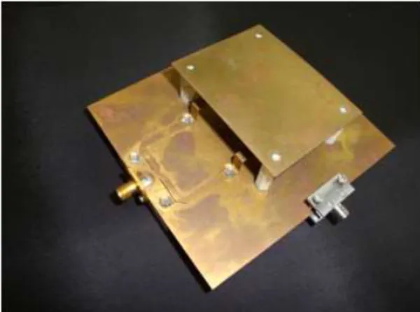
Fig. 6 shows the prototype of the proposed antenna. The structure of the antenna is designed for the air-gap structure rather than dielectric substrate, its manufacturing processes are simplified. Thus, the antenna is capable of reproducing its uniform characteristics in the mass
production process.
Fig. 6 Photograph of the antenna proto-type.
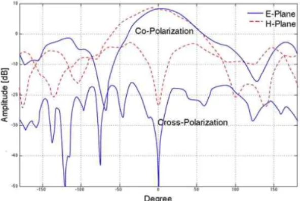
The radiation characteristic of proposed dual-polarized microstrip antenna shows a stable response all around wireless communication service frequency bands. Fig. 7 is one of the radiation patterns where center frequency is 1.96 GHz. The H and E-plane 3dB-beamwidth of the single patch at the frequency of 1.96 GHz is 82.7° and 66.5°
respectively.
It is well known that H-slot antenna inside ground plane structure improves bandwidth and coupling efficiency but cause backward radiation side effect by H-slot. In this paper, reflector is installed on the backside of antenna to avoid backward radiation side effect.
Fig. 7 Measured radiation patterns of L-strip fed antenna.
Fig. 8 Measured radiation patterns of H-shaped coupling slot antenna.
Fig. 8 shows radiation pattern of H-shaped coupling slot antenna where center frequency is 2.45 GHz. In the simulation, antenna's back reflector is set to 0.1λo to avoid backward radiation of proposed H-shaped coupling slot antenna. The H and E-plane 3dB-beamwidth of the H-shaped coupling slot antenna is 79.1° and 63.44°
respectively.
The peak gain of the L-strip fed patch is 8.58 dBi (at 2.11 GHz) and 7.51~8.57 dBi cross the passband. The peak gain of the H-shaped coupling slot antenna is 7.12 dBi (at 2.43 GHz) and 6.9~7.45 dBi cross the passband.
Ⅳ. Conclusions
The proposed antenna in this study is expected to present a variety of commercial applications by designing it further as multiple band (PCS, IMT-2000, WLAN, WiMAX) antennas. In this paper, microstrip antenna with a pair of L-feeders and H-shaped coupling slot feeding mechanism are introduced to accommodate wide band frequency area. The proposed antenna has dual-polarized structure that investigates 33.98% and 11.6% of bandwidth response respectively. The proposed antenna had the impedance bandwidth of about 10%
larger than that of the reported antenna.
Also, the structure of the proposed antenna can
be modified as an air-gap feedline type that does not use a dielectric substrate, which will simplify its manufacturing processes and realize uniform its quality for mass production. The proposed antenna is applicable to high power using base stations.
The proposed antenna is characterized as vertical and horizontal polarization from two ports. It can cover triple service band (PCS, IMT-2000, WLAN and WiMAX) and especially WLAN service band.
The proposed antenna is expected to prevent the deterioration of transmission quality caused by terminal interference or multipath fading.
References
[1] A. K. Singh, M. K. Meshram, B. R. Vishvakarma,
“L-strip proximity fed shorted rectangular microstrip antenna for mobile communication,”
Microwave and Optical Technology Letters, vol.
52, pp. 1567–1571, 2010.
[2] J. S. Jeon, “Design of wideband patch antennas for PCS and IMT-2000 service,” Microwave Journal, vol. 45, no. 7, pp. 78-86, 2002.
[3] HFSS v11.1.1, ANSYS Inc.
[4] Z. Wang, S. Fang, S. Fu, “Wideband dual-layer patch antenna fed by a modified L-strip,”
Journal of Microwaves, Optoelectronics and Electromagnetic Applications, vol. 9, pp. 89-99, Dec. 2010.
[5] X. Quan and R. Li, “A Broadband Dual-Polarized Omnidirectional Antenna for Base Stations,”
IEEE Trans. Antennas and Propagat., vol. 61, pp. 943-947, 2013.
[6] J. H. Fu1, G. H. Yang, M. Liu, Q. Wu, L. W. Li,
“The research of H-shaped coupling slot microstrip antenna array,” Proc. ICMMT 2008, pp. 1234-1237, 2008.
[7] M. Bai, J. Xing, Z. Wang, B. Yan, “Design of an
H-shape cross slotted aperture-coupled microstrip
patch antenna,” Proc. 2012 IEEE International
Workshop on Electromagnetics, pp. 1-3, 2012.
저 자 소 개 김 장 욱