- 1972 -
전력용 변압기의 온라인 PD 모니터링과 시험을 위한 UHF 기술 동향
1김 병우, 1김 윤석, 2김 창복, 3조 수영, 4최 영일, 1최 용성, 1이 경섭
1동신대학교, 2광주보건대학, 3성화대학, 4조선이공대학
A Technical Trend on UHF Techniques for On-Line PD Monitoring and Site Testing for Transformer
1Byung-Woo Kim, 1Yun-Seok Kim, 2Chang-Bok Kim, 3Soo-Young Cho, 4Young-Il Choi, 1Yong-Sung Choi, 1Kyung-Sup Lee
1Dongshin University, 2Kwang-Ju Health College, 3Sunghwa College, 4Chosun College of Science & Technology
Abstract - A field-oriented UHF system for on-line PD monitoring of transformers is designed, which has been installed inside the oil tank of a transformer. This system has successfully captured long intermittent discharge signals that hadn't been detected through conventional techniques, and solved the problem successfully. The results demonstrate that UHF technique has great advantages for on-line PD monitoring of transformers. By adopting the peak detection technique, it becomes easy and effective for the transplantation of the phase-resolved pattern recognition technique from conventional method to UHF method, and then to realize continuous on-line monitoring, source characterization and trending analysis.
1. Introduction
As for practical use, phase-resolved pattern recognition and trending analysis are the most useful tools for UHF method, just as it is for traditional technique. But because the original UHF signal is very fast, only lasts for the magnitude of nano seconds, it is extremely hard to correlate it with power cycle.
At present, people mostly fulfill this function by using the POW mode of the spectrum analyzer, but it's a rather luxury approach and inconvenient at the same time. The peak detection technique is very effective to condition the UHF signal and can accomplish the same function as SA quite easily.
So far, UHF technique has been applied in the PD detection of many power equipment, such as cable、generator and transformer, etc[1].
In this paper, the authors introduce to adopt the peak detection technique in the field-oriented UHF on-line PD monitoring system of transformers, then the two practical working instances are introduced in detail, the results indicate the effectiveness of the UHF technique and its superiority over conventional methods.
2. Experimental
Usually in the practices of UHF, the phase information of the PD is obtained by using a SA that is set to POW mode.
When considers the cost factors and the convenience reasons, the SA does not suitable to be used as a component of the stationary equipment, so the peak detection technique is adopted to condition the original UHF signals, which not only maintains the phase and magnitude info, but also lower the requirements for the digital sampling rate greatly. By doing this, the cost of the device is reduced to the maximum extent, and the traditional phase-resolved pattern recognition technique can then be transplanted to the UHF method.
The two parts of the system work independently. The stationary device will be installed on the equipment during its service life, and its main functions are: continuously monitoring the target, then decide whether there're PD or not;
making phase-resolved statistical analysis of the UHF peak
detection signals to plot charts, which is to make source characterization; recording important PD parameters and making trending analysis. The stationary part provides reserved port for the movable device to be connected in. A high-speed oscilloscope is used temporarily to make frequency domain analysis of the original UHF signals, which includes making pattern recognition by the UHF spectra and estimate the approximate time-flight information from different sensors, but these kind of work has be done by qualified researchers at present. According to the different installing modes of the sensors, two implementing schema of the system are designed. One way is on-line installation by inserting the sensor into transformer tank through the oil valve, this is the
"plug and play" mode; the other way is by pre-installing the sensor onto the manhole or hand hole cover, which must be carry on before the oiling of the transformer, in this way the sensor will be as a part of the cover and will work with the transformer permanently after installation. Special oil-proof design is required for both of these two ways, so as to guarantee the safety service of the transformer; besides, it's necessary to increase the sensitivity of the sensor while installation requirement is satisfied.
3. Results and Discussion
First let's introduce the service records of the transformer.
It is estimated that there could exist discharge faults. But time after time no PD had ever been detected through conventional PD test. Oil filtration and inspection without disassembly had also been performed several times, still no faults were found. Because of the working conditions, special mechanical equipment has been designed to ensure the installation and effective working of the system. The installing mode requires that the sensor's size have to be strictly constrained by the inner diameter of the valve. Besides, the sensor is sealed with 10 mm thickness of modified resin epoxy with relative permittivity (5.5) to avoid immediate touching of hot oil. With the existence of this material, the sensitivity of the antenna can be improved effectively, M. D.
Judd have studied the effects of dielectric windows on GIS[2], as for transformer, the principle is the same.
The background noises level inside the oil tank is very low (about 25mV), which is about two times lower than the outer environment (about 50mV). A stable and continual signal was found and recorded by the oscilloscope, see Figure 1. In order to find out its source, several layers of aluminum foil was wrapped onto the apertures at where the flange joints and all the signal lines were screened by a soft spiral iron pipe, which intention is to ensure good screening of the whole measuring system. After convinced that the interferences could be totally removed by the screening, we found that the signal still exists, then the sensor was withdrawn out of the transformer, still the signal existed, so we concluded that the signals are interferences brought about by the switched power of the amplifier.
During the period of monitoring, three intensive signals 2007년도 대한전기학회 하계학술대회 논문집 2007. 7. 18 - 20
- 1973 -
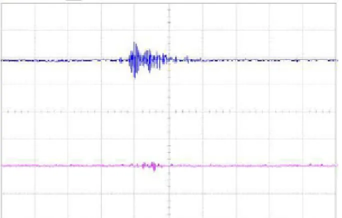
were captured by the measuring system. The amplitudes of the signals were about 400mV, which were much higher than that of the background noises (see Figure 2). When each signal was captured, the operations of the transformer tap changer could be excluded definitely. The time intervals between two signals were seven hours approximately. The time domain waveform of the signals indicated that they were much likely to be discharges, but it was kept uncertain whether they were generated inside the transformer oil tank or other electrical equipments' operation coupled into the transformer from the power lines.
Fig. 1. Typical noise signal from the power system.
Fig. 2. A typical suspicious discharge signal.
The typical UHF PD signals of the yellow phase are shown in Figure 3. It shows that the background of the manhole antenna is about 30mV, while the PD signal is approximately 150mV. Besides, each time the waveform of the signal almost keeps the same, which indicate that it is a monotype discharge. The case of the hand hole antenna is analogous as the manhole antenna, but the signals are much smaller. Because the signals become steady and low in a few minutes, we conclude that it is gas cavity discharge in oil or corona discharges on small conductor burrs which soon be melted down by the PD energy. The results demonstrate that the sensitivity of the UHF system is high enough to detect very small discharges in transformers.
Fig. 3. Typical PD signals from Manhole and hand hole antenna when the yellow phase is energized.
4. Conclusion
The authors introduce to adopt the peak detection technique in the field-oriented UHF on-line PD monitoring system of transformers. Peak detection technique makes it easier and cheaper for UHF method to import conventional phase-resolved pattern recognition technique and trending analysis, which makes it more practicable for on-line utilization of UHF technique.
Acknowledgement
This work was financially supported by MOCIE program (I-2006-0-092-01).
[References]
[1] Okubo H, Suzuki A Frequency component of current pulse waveform in partial discharge measurement[A] 9th ISH [C] Graz ,August 25-29, 1995.
[2] M.D. Judd, O. Farish, J.S. Pearson, and B.F. Hampton,
"Dielectric windows for UHF partial discharge detection", IEEE Trans. Dielectric. Elect. Insulation, Vol.8, pp.
953-958, Dec. 2001.