http://dx.doi.org/10.5229/JKES.2013.16.3.138
− 138 −
Effect of the Anode-to-Cathode Distance on the Electrochemical Reduction in a LiCl-Li 2 O Molten Salt
Eun-Young Choi*, Hun-Sook Im, and Jin-Mok Hur
Korea Atomic Energy Research Institute, Daedoek-daero 989-111, Yuseong-gu, Daejeon 305-353, Republic of Korea (Received July 17, 2013 : Accepted July 30, 2013)
Abstract : Electrochemical reductions of UO
2at various anode-to-cathode distances (1.3, 2.3, 3.2, 3.7 and 5.8 cm) were carried out to investigate the effect of the anode-to-cathode distance on the electrochemical reduction rate. The geometry of the electrolysis cell in this study, apart from the anode-to-cathode distance, was identical for all of the electrolysis runs. Porous UO
2pellets were electrolyzed by controlling a constant cell voltage in molten Li
2O-LiCl at 650
oC. A steel basket containing the porous UO
2pellets and a platinum plate were used as the cathode and anode, respectively. The metallic products were characterized by means of a thermogravimetric analyzer, an X-ray diffractometer and a scanning electron microscope. The electrolysis runs conducted dur- ing this study revealed that a short anode-to-cathode distance is advantageous to achieve a high current density and accelerate the electrochemical reduction process.
Keywords : Electrochemical reduction, Uranium oxide, Uranium, Li
2O-LiCl molten salt
1. Introduction
The FFC (Fray–Farthing–Chen) Cambridge process has been regarded as an innovative method for the electrochemical reduction of solid oxides into their metals because it is simple, cost-effective, and environmentally friendly. Ever since the direct reduction of TiO
2to titanium metal in a molten salt electrolysis cell was demonstrated in the first report on the FFC process,
1)the application of the process has been expanded to the reduction of the various metal oxides such as SiO
2,
2)Ta
2O
5,
3)Fe
2O
3,
4)SnO
2,
5)Tb
4O
7,
6)Nb
2O
5,
7-9)Cr
2O
3,
10,11)and CeO
2.
12)In particular, the electrochemical reduction of spent oxide fuel (mainly consisting of UO
2) to a metallic form has been successfully employed in pyroprocessing technology for the closed nuclear fuel cycle.
13,14)Pyroprocessing based on molten salt electrolysis is one of the key technologies for reducing the amount of spent nuclear fuel and destroying toxic waste products, such as the long-life fission products in spent nuclear fuels. During pyroprocessing, the
electrorefining process that is used to separate and recover uranium, plutonium and other actinides in molten chloride media cannot accept the spent oxide fuel directly, because the actinide oxides are not d i s s o l v e d i n t h e c h l o r i d e s a l t . T h u s , t h e electrochemical reduction of the spent oxide fuel to a metallic form is a head-end step of the electrorefining process.
15-29)In the electrochemical reduction process, oxides fuels are loaded at the cathode in molten LiCl so as to dissolve oxide ions. The cathode reactions are as follows
1):
Li
++ e
−→ Li (1)
MO
2+ 4Li → M + 2Li
2O(salt phase) (2) MO
2+ 4e
−→ M(actinide) + 2O
2−(salt phase) (3)
Li
2O produced by reaction (2) in molten LiCl is dissociated into Li
+and O
2−:
Li
2O → Li
++ O
2−(salt phase) (4)
When a platinum anode is employed, oxygen ions are oxidized to produce oxygen gas on the anode surface, as follows:
*E-mail: [email protected]
2O
2−(salt phase) → O
2(gas) + 4e
−(5)
When an electrical potential is applied, the actinide metal oxide is reduced to metal and remains at the cathode. The oxygen ion (O
2−) produced at the cathode is transported through the salt and discharges at the anode to form O
2gas. Li
2O is initially added to molten LiCl to speed up the electrochemical reaction and prevent the anodic dissolution of the platinum. The diffusion of O
2−ions from the inside of the oxide fuel to the anode surface via the bulk salt determines the reduction rate during electrolysis.
20,30-33)The commercialization of the electrochemical reduction process can be expedited if a more efficient electrolysis cell can be designed for a large-scale production. Determining configuration, capacity, size and material of the cell is essential to design a scaled- up electrochemical reduction process. The cell configuration includes the heat shields, the location of the electrodes, the shape of the cathode and anode, the anode shroud, the anode/cathode surface area ratio, the gas outlet at the anode, and the anode-to-cathode distance. Many researchers have tried to increase the efficiency of electrochemical processes by considering the influence of the anode-to-cathode distance.
34-37)Kasherman and Skyllas-Kazacos
34)investigated the effect of the anode-to-cathode distance on the cell potential and electric bath resistivity in the Hall-Heroult process for aluminum production in molten salt bath.
In the electrochemical reduction process of metal oxide for its metal production in molten salt, it was has been predicted that a short anode-to-cathode distance will be advantageous to improve the energy efficiency.
38,39)However, the effect of the anode-to- cathode distance on the electrochemical reduction process has not experimentally verified thus far. In this study, electrochemical reductions of porous UO
2pellets were carried out in a molten Li
2O-LiCl salt at various anode-to-cathode distances (1.3, 2.3, 3.2, 3.7 and 5.8 cm) and their reduction rates were compared.
2. Experimental
2.1. Materials
Anhydrous LiCl (99.5% purity, Alfa Aesar) and Li
2O (99.5% purity, Alsa Aesar) were used as the electrolytes. The LiCl salt was dehydrated and kept in
an Ar glove box beforehand. The porous UO
2pellets were prepared as follows: After mixing U
3O
8powder with 0.2 wt.% of N,N’ ethylene bisstearamide (Sunkoo Ltd., Korea), we placed the mixture in cylindrical molds (with a diameter of 6 mm and a height of 8 mm) and pressed it into pellets with a pelletizer.
Next we placed the cylindrical mixture in a furnace under a vacuum and heated it to 700
oC at a heating rate of 2
oC/min. This temperature was maintained for 1 h to remove the N,N’ ethylene bisstearamide from the mixture. The remaining U
3O
8was heated to 1350
oC at a heating rate of 2
oC/min, and this temperature was maintained for 12 h to covert the U
3O
8to UO
xand to release the oxygen gas. Finally, the mixture was cooled to room temperature at a cooling rate of 5
oC/min. The value of x in UO
xwas determined by the potentiometric titration method to be 2.112. In this report, we refer to the prepared porous UO
2.112pellets simply as porous UO
2pellets.
2.2. Electrochemical reduction of UO
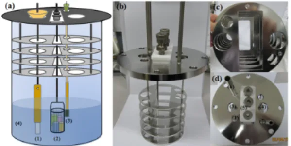
2Fig. 1a shows a schematic of the cell used for the electrochemical reduction process. The electrolysis cell consists of a crucible, salt and a flange (a set of heat shields with ports), where the salt makes contact with the electrodes and probes. A photograph of the flange used for this study is presented in Fig. 1b. Figs 1c and 1d show its bottom and top, respectively. The small and round ports of the flange are for the reference electrode ((1) in Fig. 1d) and for salt
Fig. 1. (a) Schematic diagram of the electrochemical cell:
(1) Pt anode with a MgO shroud, (2) cathode basket
containing UO
2forms, (3) Li-Pb reference electrode and
(4) 1 wt% Li
2O-LiCl molten salt, (b) photographs of the
flange for the electrochemical cell, (c) bottom of the
flange and (d) top of the flange; (1) for the reference
electrode, (2) salt sampling, (3), (4), and (5) cathode or
anode, (6) gas outlet and (7) gas inlet.
sampling ((2) in Fig. 1d), respectively. The rectangular port ((5) in Fig. 1d) and two adjacent ports ((3) and (4) in Fig. 1d) are for the anode and (or) cathode.
Three screw joints are placed on the cover of the rectangular port, which can fix the rods of the anode or cathode. First, 800 g of LiCl was put in a stainless steel crucible (diameter, 95 mm) at room temperature.
The reactor was heated to 650
oC and maintained at that temperature. Then, 8.0 g of Li
2O was fed into the reactor to reach the desired concentration. After the complete dissolution of Li
2O, the electrodes were lowered into the molten salt. A liquid Li-Pb alloy (32 mol% Li) was used as a reference electrode. We placed 1 g of the Li-Pb alloy in an MgO tube with an inner diameter of 5 mm and a porous bottom. A tantalum wire (with a diameter of 0.5 mm) was then put into the tube and immersed in the liquid alloy for use as an electrical lead. A cylindrical cathode basket (20 mm in diameter) was surrounded with a 325 mesh sheet (sieve opening of 45 µ m in size) to contain the UO
2forms. Both the bottom and the mesh sheet of the basket were electrically conductive. In addition, we surrounded a 10 mm wide plate-type platinum (Pt) anode with an MgO shroud to provide a path for the oxygen gas produced on the anode surface. The exposed surface areas of the anode and cathode were constant. An Agilent E3633A power supply was used for the voltage control electrolysis process in order to reduce the UO
2. The cathode potential during the electrochemical reduction was monitored with a digital multimeter (Agilent, 34405A). During the electrolysis run, the variation of the Li
2O concentration in the molten salt was checked by a titration method, as follows. A molten salt sample of 0.4 g was taken from the reactor using a pipette and was dissolved in distilled water. The dissolved alkali solution was then titrated with 0.1 N HCl.
2.3. Characterization of metallic U reduced from UO
2After the experimental run, the reduced sample was rinsed with distilled water to remove the residual salt. The reduction conversion of UO
2was determined by means of a thermogravimetric analyzer (TGA, TG/DTA 6300, Seiko Instruments Inc.). A 20 mg sample of metallic U was loaded into the Pt crucible for the TGA measurement and
heated to 600
oC at a heating rate of 10
oC/min in an air atmosphere. The surface morphology and the crystalline structure of the products were observed with a scanning electron microscope (SEM, Philips, XL-30) and a X-ray diffractometer (XRD, Rigaku MiniFlex), respectively.
3. Results and Discussion
The electrochemical reduction run was conducted with 29.9 g of P-55% in 1 wt% Li
2O-LiCl molten salt at 650
oC. The anode-to-cathode distance was 1.3 cm.
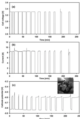
Fig. 2 shows the electrolysis curves of (a) the cell voltage, (b) the current, and (c) the cathode potential as a function of time. The electrolysis run at a constant voltage (3.3 V) was interrupted at appropriate intervals, and the open circuit potential of the cathode was measured so that we could monitor the formation of lithium metal and prevent it from being deposited
Fig. 2. Plots from the electrochemical reduction of UO
2(29.9 g) in 1 wt% Li
2O-LiCl at 650
oC (the used anode-to-
cathode distance used was 1.3 cm): (a) the cell voltage vs
time, (b) the current vs time, and (c) the cathode potential
vs time.
excessively on the cathode surface.
32,33)The cathode potential was lowered to approximately − 0.85 V (Fig.
2c) by applying a cell voltage of 3.3 V (Fig. 2a) because a cyclic voltammetry test in our previous study
40)showed that UO
2is reduced at a potential that is more negative than − 0.60 V. The Li/Li
+potential measured during the interruption of the electrolysis run was − 0.60 V against the Li-Pb reference electrode. The response current ranged from 7.5 to 10 A (Fig. 2b). This run was finally finished after 137% (16.3 A h) of the theoretical electric charge had passed. The cathode basket was cut along the radial direction in a high-purity argon glove box.
A photograph of a cross-section of the reduced pellets (inset of Fig. 2c) shows that U was metallic grey after a charge supply of 150%, unlike brown UO
2.
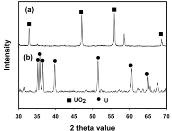
The crystalline structure of the fresh UO
2and the electrochemically reduced UO
2was compared by means of XRD. As shown Fig. 3a, the main sharp peaks, which can be assigned to UO
2, appear near 2 θ = 33, 47, 56 and 69. On the other hand, in the XRD results of the reduced sample, the main sharp peaks of UO
2disappeared and new sharp peaks, which can be assigned to metallic uranium, appear at near 2 θ = 36, 40, 51, 61, and 65 (Fig. 3b).
41)These observations indicate that uranium oxide was successfully reduced to metallic uranium during the electrolysis process.
The microstructure of the fresh UO
2(Figs. 4a and 4b), and the electrochemically reduced UO
2(Figs. 4c and 4d) were compared by means of SEM. After the
electrolysis runs, it was observed that the particles were more connected and enlarged. In particular, the structure is sintered together and resembles a metal sponge with a nodular structure induced by the differences in the densities of the UO
2and metallic uranium.
The electrochemical reductions of UO
2at various anode-to-cathode distances were also conducted in a manner similar to that of the electrolysis run using anode-to-cathode distance of 1.3 cm (shown in Fig.
2). Various anode-to-cathode distances were used by placing the anode and cathode at different positions (ports, (3), (4) and (5) in Fig. 1d) in the flange top of the electrolysis cell. The positions of the anode and cathode for the various anode-to-cathode distances are presented in Fig. 5. The anode-to-cathode distances were measured at the closest distance between the anode and the cathode. All of the geometry factors of the electrolysis cell, in this case the position of the reference electrode, the height of the anode shroud, the direction of the anode plate, and the immersion height of the surfaces of the anode and cathode were identical except for the anode-to-cathode distances.
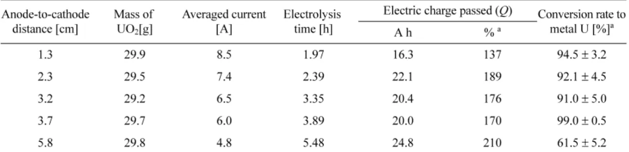
The results of the electrochemical reductions at various anode-to-cathode distances are given in Table 1. The mass of the UO
2used here was approximately 29~30 g. The supply of the charge
Fig. 3. XRD patterns: (a) UO
2before the electrochemical reduction and (b) metallic U after the supply of 150 % of the charge.
Fig. 4. Cross-sectional SEM images of UO
2: low-
magnification view (1000 × ) (a) and high-magnification
view (3000 × ), (b) before the electrochemical reduction
process; low-magnification view (1000 × ) (c) and high-
magnification view (3000 × ), (d) after the electrochemical
reduction process.
was terminated when the constant open circuit potential was maintained for a certain period of time, which resulted in the different electric charges passed for each run. The theoretical charges were calculated using the following equation
33):
Q = 100q/[nF(w
UO2/M
UO2)] (6)
Here, n is the number of electrons involved in the cathode reaction (3), F, is the Faraday constant (26.8 A h/mol), w
UO2is the weight of UO
2loaded in the cathode basket (g), M
UO2is the molecular weight of UO
2(270.03 g/mol), and q is the electric charge passed for the electrolysis (A h). While 137% of the theoretical charge (Q) was supplied f or the electrolysis run using an anode-to-cathode distance of 1.3 cm, more than 170% of the theoretical charge was supplied for the other runs using longer anode-
to-cathode distances. For each electrolysis run, the averaged currents (the vacant dots) with the minimum and maximum values are plotted, as shown in Fig. 6. The maximum currents correspond to the initial sharp drop when cell voltage was newly applied after a certain period for the measurement of the open circuit potential. The sharp drop in the current may be due to the double layer charging period as shown in a previous publication.
10)The minimum currents correspond to the current measured in the vicinity of the end-point of the electrolysis run. These decreases in the current at the latter part of the electrolysis run result from a decrease in the reacting surface area of the metal oxide as the reduction of UO
2proceeds. In Table 1, as the anode-to-cathode distance increases, an increase in the electrolysis time caused by the decreased current was observed. It should be noted Table 1. The results of electrolysis runs of UO
2forms at various anode-to-cathode distances (constant voltage electrolysis - 3.3 V, in 1 wt% Li
2O-LiCl at 650
oC)
Anode-to-cathode distance [cm]
Mass of UO
2[g]
Averaged current [A]
Electrolysis time [h]
Electric charge passed (Q) Conversion rate to metal U [%]
aA h %
a1.3 29.9 8.5 1.97 16.3 137 94.5 ± 3.2
2.3 29.5 7.4 2.39 22.1 189 92.1 ± 4.5
3.2 29.2 6.5 3.35 20.4 176 91.0 ± 5.0
3.7 29.7 6.0 3.89 20.0 170 99.0 ± 0.5
5.8 29.8 4.8 5.48 24.8 210 61.5 ± 5.2
a