* 동서대학교 대학원 메카트로닉스공학과([email protected])
** 교신저자 : 동서대학교 메카트로닉스공학과([email protected])
접수일자 : 2012. 08. 10 심사(수정)일자 : 2012. 11. 21 게재확정일자 : 2012. 12. 10
Integration of 4-20mA Current Loop Receiver Instrument Variable Linear Mapping
롱치록
*
․박수홍**
Integration of 4-20mA Current Loop Receiver Instrument Variable Linear Mapping
Wong Chii Lok * ․Soo-Hong Park **
요 약
본 연구에서는 4-20mA 수신기를 가진 선형매핑용량의 새로운 집적방법에 대한 것이다. 본 연구에서 제안 한 모듈은 즉각적으로 기구변환을 사용자들이 편리하게 할 수 있도록 하였다. 구성은 직렬통신포트에 콘솔명 령을 사용하여 쉽게 배치하였다. 전류루프나 디폴트전류송신기에서의 중단되는 현상을 표시에 의하여 쉽게 발견되도록 하였다. 이러한 모듈의 적용과 실험에 대하여 상세히 연구하였다.
ABSTRACT
In this paper, a new integration of linear mapping capability with 4-20mA current loop receiver. This module allow user to change instrument variable instantly. Configurations are easy to set by using console command through serial communication port.
Break in current loop or faulty current transmitter are easily detect through indicator. The implementation of the module and the test results are discussed
키워드
Linear Mapping, process-monitoring , current loop receiver 선형 사상, 프로세스 관찰 , 전류수신기
Ⅰ. INTRODUCTION
4-20mA current loop is a standard in many in- dustrial process-monitoring applications. It is a common method of transmitting sensor measured physical parameters such as temperature, pressure, speed, liquid flow rates, etc.
Brief history about the current loop application,
the 4-20mA current signaling was introduced to
replace 3-15 psi pneumatic control system due to
low power requirement and low susceptibility to
noise. Furthermore, 4-20mA current signal wires
are easier to install and maintain than pneumatic
pressure lines and electronics allowed more com-
plicated control algorithms [1]. It has become a
common method of transmitting sensor information
in many industrial process-monitoring applications.
This paper describes the design of a 4-20mA current loop receiver with instrument variable linear mapping feature. The entire system uses typical microcontroller as the main system controller. A current receiver chip RCV420 from Burr-Brown is used in this project due to its precision current signal conversion and the ease of implementation.
First, the system will retrieve stored parameters from EEPROM and perform initialization. Parts of the EEPROM parameter will be used to calculate and form linear mapping equation [5]. Afterwards, the system will keep perform Analog-to-Digital, ACD reading for voltage, current and RCV420 chip voltage signal. The system can be interrupt for console commands through serial communication port. This system also provide user to manually change the upper and lower boundary of instrument variable that are going to be connected.
This paper is organized as follows: Section 2 states problem definition and goals of this project;
and it reviews some brief knowledge about 4-20mA current loop system Section 2 introduces the overall architecture of the proposed current loop system and it presents hardware design of current receiver In Section 3, describes program flow and algorithm for linear mapping Section 3, shows the overall system operation of the module. Finally, Section 4 present results and conclusion of this paper.
Basically, this system performs 4 to 20mA current loop conversion into instrument variable readings. Main motivation behind this project is to provide a less maintenance, high precision conversion, configurable and long term reliable performance receiver. Therefore, in this project, an attempt has been done to implement current loop application receiver with most useful feature within limited resources. [7][8][9]
Ⅱ. PROBLEM DEFINITION& LITERATURE SURVEY
The goal of this work is to implement 4-20mA current loop converter to serial data with instrument variable linear mapping availability. Main objectives are listed below:
- to enable current loop conversion with high precision.
- easy adaptability to different types of 4-20mA current transmitter.
- to configure instrument variable easily.
It is useful when transmit sensor information to a remote location via a current loop over long distances which may exceed 1000 feet, or more.
Advantages of current loop application module [1]:
- lossless nature,
- lower-sensitivity to induced noise, - live-zero offset,
- fail-safe operation,
- scalability contributes to its longevity.
Disadvantages of current loop:
- high power consumption,
- read access only, problems diagnosis not available
The current loop’s operation is described as in
fig.1. There are four individual elements found in a
typical current loop application: sensor/transducer,
transmitter, power supply and receiver/monitor. All
four elements are connected in a closed series
circuit loop configuration. The basic theory behind
the current loop application is straightforward. A
sensor’s output voltage is first converted to a
proportional current by transmitter. In 4-20mA
current loop application, 4mA normally representing
the sensor’s zero-level output and 20mA represent
as the sensor’s full-scale output. The current loop
is a series configuration therefore current will be
precisely equal through all components. Then, a
receiver at the remote end converts the 4-20mA
current back into a voltage which in turn can be
further processed.
Fig. 1 Typical components in current loop application [1]
There is several type of current loop wiring options can be used depend of the associated control panel and transmitter. 2 wire loop, 3 wire current source/sink and 4 wire fully isolated wiring options are available. Each wiring option has advantages and disadvantages [2].
The objective of this project is to measure 4-20mA current signal output from sensor with high precision and further relating 4-20mA current signal to instrument variable by linear mapping feature. The overall system architecture is shown in fig.2.
The proposed system consists of two separate current loops which common power supply is isolated. The current loop receiver part contains precision 4-20mA current loop sensing, voltage level measure, onboard current consumption monitoring and serial communication [6].
There is a chip, RCV420 introduced by Burr-Brown which is designed for precision 4-20mA current loop receiver for complete 4-20mA to 0-5V conversion [3]. The RCV420 features 0.1%
overall conversion accuracy. The RCV420 converts the 4-20mA signal and then level shifts this down by 1.25V to achieve 0-5V range.
XTR110 RCV420
20mA Power Supply 20mA
+
+ -
-
XTR110 RCV420
24Vdc -
20mA 20mA
-
- +
+ + Sensor 1
Sensor 2
Fig. 2 Two current loops with common power supply diagram
MAXIM is use in this project to measure overall current consume by the receiver. It is low cost, small and features a voltage output that eliminates the need for gain-setting resistors. Sets of full-scale current reading are selectable by picking up suitable external-sense resistor.
As for the software application development, ADC reading from ATmega128 has to convert into instrument variable display. Linear mapping equ- ation is introduced for easy calibration 4-20mA current signal to full scale of instrument variables.
The full scale of instrument variable can be change easily through serial communication port by cha- nging upper and lower boundary. With linear equation characteristic, 4-20mA current signal can be map into ascending or descending single variable linear equation. Digital reading 0 represent as lower limit boundary or "live-zero" to detect break or open fault in current circuit 1023 reading represent as upper limit boundary.
Ⅲ. HARDWARE DESIGN OF THE CONTROL SYSTEM
Parts of 4-20mA current loop receiver hardware structure is shown and described. The hardware development was done after several revisions.
A..Current Loop Receiver
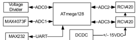
The basic setup of the current loop receiver unit includes ATmega128 microcontroller, two RCV420 precision current loop receivers and a MAX4073F low cost high-side current sense amplifier. Fig.3 shows the block diagram for the current loop receiver.
ATmega128
DCDC MAX4073F ADC3
Voltage Divider
RCV420 RCV420 ADC2 ADC1
MAX232 UART +/- 15VDC
ADC0
Fig. 3 Block diagram for 4-20mA current loop receiver
For the RCV420 chip connection, both supplies pin should be decoupled with 1uF capacitors as close to the amplifier as possible. To avoid gain and CMR errors introduced by external circuit, connect grounds as indicated, ground resistance has to be minimized. The input current loop signal should be connected to either +In or –In, depending on its polarity, and returned to ground through the center tap, CT. The RCV420 converts the 4-20mA current signal to 0-5V output by levels shifts. By using a single supply approach, a level-shifted output will not easily be accomplished.
ADCDC converter SPD1R5-12-1515 from Power Plaza is used to supply +/-15V to RCV420.
MAX4073F use a sensing resistor to sense current. Typical sense voltage range is between 10mV to 150mV. 1Ohm current sensing resistor with 3Watts power dissipation is used in this design to sense full range of current up to 0.1Ampere.
B Current Loop Transmitter
Due to lack of 4-20mA current transducer, a cheap transmitter has been design and made for the complete system verification or calibration purpose without the need for expensive transducer. Fig.4 shows the block diagram for current loop transmitter.
XTR110 is a three-wire 4-20mA current loop transmitter from Burr-Brown [4]. Essentially, it is a precision single supply voltage to current converter with an internal 10V reference and input resistor network for span offsetting. Various input output ranges are available by pin strapping so that 0 to 5V or 0 to 10V inputs can be used to get 0 to 20mA or 4 to 20mA outputs. A variable resistor is connected to XTR110 to vary current output in range of 0 to 20mA above.
XTR110 Variable
Resistor
Fig. 4 Block diagram for 4-20mA current loop transmitter
Parts of current loop receiver firmware deve- lopment is shown and described. The firmware is development by using ICCAVR compiler.
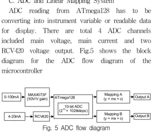
C. ADC and Linear Mapping System
ADC reading from ATmega128 has to be converting into instrument variable or readable data for display. There are total 4 ADC channels included main voltage, main current and two RCV420 voltage output. Fig.5 shows the block diagram for the ADC flow diagram of the microcontroller
0-100mA MAX4073F
(50V/V gain) ATmega128 10-bit ADC (210= 1024steps)
Mapping A
(y = mx + c) Output A
4-20mA RCV420 Mapping B
(y = mx + c) Output B
Fig. 5 ADC flow diagram
ATmega128 features a 10-bit successive appro- ximation ADC and connected with 5V as reference voltage. The smallest resolution of the ADC is about 210 = 1024 steps and each steps represent 5/1024 = 0.00488V. Each milli ampere from RCV420 after current-voltage conversion is about 0.3125V.
Itis approximate 65 times greater than each resolution steps of ADC and sufficient enough for this project requirement.
Flexible single variable linear mapping is introduced in order to convert ADC reading into instrument variable for display range of mapping can be done by command in upper and lower boundary limit of instrument range. The upper and lower value will be used to calculate gradient and intercept value for y = mx + c equation as shown in fig.6.Zero and 1023 ADC reading represent absolute lower and upper limit respectively.
D. Console System
New mapping range can be set through console
port by $UPPER and $LOWER command. GRAD-
IENT, INTERCEPT, UPPER and LOWER are
retrieve from ATmega128’s EEPROM. Once after a
new upper or lower is set, new GRADIENT and
INTERCEPT value will be calculate and store into EEPROM. The gradient value is calculated without 0 and 1023 digital reading from ADC; while intercept is calculated when ADC equal 1022.
rangeSet
GRADIENT = (UPPER – LOWER) / (1022-1) INTERCEPT = (UPPER - (GRADIENT * 1022))
End
Fig. 6 RangSet function flow chart
Header information of output format also can be change easily through console port through console port.
The entire system operation consists of two main routines: parameter setting for the microcontroller output; main operation flow for console mode checking, ADC read and output print.
E. Parameter Settings
The user interface of the system is simple to operate. The default port for console communication is 9600 baud rate none flow control, 8 bits data none parity and 1 stops bits.
Table. 1 Console commands
Command Description
$AT<CR><LF> Command mode response
$HEADER?<CR><LF> Get header string
$HEADER,<PARAMET
ER><CR><LF> Set header string
$ID?<CR><LF> Get id number
$ID,<PARAMETER><C
R><LF> Set id number
$UPPER?<CR><LF> Get upper boundary
$UPPER,<PARAMETER
><CR><LF> Set upper boundary
$LOWER?<CR><LF> Get lower boundary
$LOWER,<PARAMETE
R><CR><LF> Set lower boundary
$EXIT<CR><LF> Command mode exit
All commands are start with dollar sign, $. User can key in valid command as shown in Tab.1.
Most of the commands are used to check and change the output sentences of the ATmega128. If invalid command is entered, error message will be replied. All the parameters that have been changed will be saving in EEPROM.
F. Main Operation
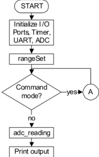
The main operation of the current loop receiver can be shown in the flow chart in fig.7.
START Initialize I /O Ports, Timer, UART, ADC
Command mode?
rangeSet
adc_reading Print output
A
no
yes
Fig. 7 Main operation flow chart
When the microcontrolleris powered up, it will begin with initialization of I/O ports, timer, UART and ADC. All saved parameters such as header, id and etc. will be retrieving from EEPROM. The gradient and intercept value will be calculated to form single variable linear equation for the instr- ument variable mapping.
The main flow of the program will keep perform
ADC conversion for voltage, current and both
4-20mA current reading. An LED is use to indicate
when "live-zero" is detected from the 4-20mA
current signal sensing. The current sensing is use
to monitoring the onboard power consumption while
voltage sensing is to make sure there is minimum
voltage for the DCDC converter which is critical for
Vsense(mV) Actual(V) Ideal(V) Error(%)
57.2 2.806 2.86 -1.888111888
57.8 2.866 2.89 -0.830449827
66.5 3.24 3.325 -2.556390977
67.5 3.32 3.375 -1.62962963
RCV420 chip precision conversion operation.
User key in command with be handle by UART receive interrupt routine. Once a command input end with new line, main program flow will be suspend to perform command mode operation. The command mode operation flow is shown fig.8.
A
Command DataReady?
Valid Command?
END
Command operation yes
no no yes
Fig. 8 Command mode flow chart
The output from the board is through UART less than a second which form with a sentence.
The sentence is start with dollar sign, $ and follow by parameters and readings such as: header, id, instrument variable, validity and checksum
Ⅳ. RESUTLS
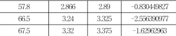
Tests have been done for reliability and performance. The current consumption of the board is check with multimeter and on board current sensing circuit. A 1Ohm sensing resistor is combining with MAX4073F to check current up to 0.1Ampere. Tab.2 shows 4 typical 4-20mA current sensing board’s current consume level result.
Table. 2 MAX 4073F current sensing test
Tests have been done for reliability and perfo- rmance. The current receiver is connected to the self made 4-20mA current transmitter. 12V Power supply and a multimeter are connected in series of current loop in between current receiver and transmitter. The multimeter is used to measure supplied current signal. The current transmitter is adjusting to give different current level while voltage is measured by using another multimeter at ADC pin of microcontroller that connected to RCV420 chip. Measured supplied current signals are then calculate for voltage by formula 0.3125V/mA–
1.25V and compare with measured voltage level respectively. Tab.3 shows the RCV420 current signal test in between 4 to 20mA. Result shows error is significantly high when only below 5mA current signal
Table. 3 RCV420 4-20mA current signal test Current
Loop(mA) Actual(V) Ideal (V) Error (%)
4.07 0.0304 0.021875 38.97142857
5.11 0.357 0.346875 2.918918919
6.1 0.667 0.65625 1.638095238
8.07 1.287 1.271875 1.189189189
10.03 1.903 1.884375 0.988391376
12.05 2.535 2.515625 0.770186335
14.02 3.16 3.13125 0.918163673
16.06 3.78 3.76875 0.298507463
18.07 4.4 4.396875 0.071073205
19.96 4.99 4.9875 0.050125313
The next test is done to test the instrument variable linear mapping reliability. In the test, lower and upper boundaries are set to 0 and 200 respectively through console communication port.
The ideal mapping value is calculated by few steps.
First, output voltage of RCV420 is measured and converts to 10-bit ADC digital reading with 5V as reference voltage. Next, the calculated digital reading substitute into y=mx+c equation to find the ideal mapping value where gradient and intercept are calculated from fig.6 equation. Results in tab.4 show that the actual mapping is less than 0.5%
difference from ideal mapping. Only current signal below 5mA shows greater error. The live-zero condition when current below 4mA is test successfully.
Overall, output is linear precisely with 4mA as 0V and 20mA as 5V. The errors may cause from self made current transmitter due to hard tune into desired current signal value below 8mA. A proper current transmitter should be use for better testing result.
Table. 4 Mapping comparison error result Current
Loop(mA)
Mapping Ideal
Mapping
Actual Error (%)
3.06 -1 -1 0
4.07 0.875 0.06 -93.14285714
5.06 13.25 12.92 -2.490566038
6.05 25.625 25.72 0.370731707
7.06 38.25 38.19 -0.156862745
8.01 50.125 50.06 -0.12967581
9.09 63.625 63.5 -0.196463654
10.06 75.75 75.64 -0.145214521
11.04 88 87.95 -0.056818182
12.05 100.625 100.57 -0.054658385
13.02 112.75 112.72 -0.026607539
14.06 125.75 125.63 -0.095427435
15.04 138 137.93 -0.050724638
16.01 150.125 150.01 -0.076602831
17.01 162.625 162.49 -0.083013067
18.08 176 176.01 0.005681818
19.05 188.125 188.18 0.02923588
19.92 199 199.11 0.055276382
20.01 1 1 0
A 4-20mA current loop receiver was designed and tested within a short time frame with efforts and proper planning. Few researches have been done in order to understand the principal and
implementation of 4-20mA current loop receiver.
Most of the development times were spent in testing and enhancing functionality of the system
REFERENCES
[1] Building Automation Products Inc., Unde- rstanding 4-20mA Current Loops Application Note: Building Automation Products Inc., 2006.
[2] Acromag, Introduction to the Two-Wire Transmitter and the 4-20mA Current Loop:
Acromag, 2008.
[3] Burr-Brown, RCV420 Data sheet, 2009.
[4] Texas Instruments, XTR110 Data sheet, 2009.
[5] Tony R. Kuphaldt, Chapter 23 Analog ele- tronic instrumentation: Lessons in Industrial Instrumentation, 2011.
[6] Cardno B. Carolina M, Design, Elaboration and Implementation of 4-20mA Current to Profibus PA Converter, 2008.
[7] NaNa Sun, Soo-hong Park ,“Hull Structure Design of a small scale Oceanographic Buoy”, The Korea Institute of Electronic Comm- unication Sciences, Vol. 6, No. 1, pp. 130-135, 2010.
[8] Wonbu Lee, Soo-hong Park, “A study on the Automatic ocean wave observation buoy system ”, The Korea Institute of Electronic Communication Sciences, Vol. 6, No. 2, pp.
268-273, 2011.
[9] Wonbu Lee, Soo-hong Park, “Development of the Servo Motion Controller using Gyro Sensor“, The Korea Institute of Electronic Communication Sciences, Vol.5 , No. 5., pp.
493-498, 2010.
저자 소개
롱치록(Wong Chii Lok)
2011년 7월 말레지아 MultiMedia University 졸업 (공학사)
2013년 8월 동서대학교 대학원 메카 트로닉스공학과 졸업예정
※ 관심분야 : 마이트로프로세서응용
박수홍(Soo-Hong park)