JPNT 7(3), 127-138 (2018)
https://doi.org/10.11003/JPNT.2018.7.3.127 JPNT Journal of Positioning,
Navigation, and Timing
1. INTRODUCTION
The global positioning system (GPS) was originally developed for the U. S. military in the 1970s (Kaplan &
Hegarty 2006). Recently, the GPS has become one of the most popular technologies of navigation. The widespread usage of GPS in terrestrial, marine, and airborne applications has been precipitated by its accuracy, global availability and low cost of user equipment. Additionally, military GPS applications require enhanced robustness against unintentional or intentional interferences such as jamming and spoofing signals (Jung et al. 2014). The
Development of Anti-Spoofing Equipment Architecture and Performance Evaluation Test System
Junwoo Jung
1†, Sungyeol Park
1, Jongchul Hyun
1, Haengik Kang
1, Kiwon Song
2, Kapjin Kim
2, Youngbum Park
21
Precision Guided Munitions Research Center, LIG Nex1, Sungnam 13488, Korea
2
The Third R&D Institute - 4, Agency for Defense Development (ADD), Daejeon 34186, Korea
ABSTRACT
Spoofing attacks including meaconing can provide a bogus position to a victim GPS receiver, and those attacks are notably difficult to detect at the point of view on the receiver. Several countermeasure techniques have been studied to detect, classify, and cancel the spoofing signals. Based on the countermeasure techniques, we have developed an anti-spoofing equipment that detects and mitigates or eliminates the spoofing signal based on raw measurements. Although many anti-spoofing techniques have been studied in the literatures, the evaluation test system is not deeply studied to evaluate the anti-spoofing equipment, which includes detection, mitigation, and elimination of spoofing signals. Each study only has a specific test method to verify its anti-spoofing technique. In this paper, we propose the performance evaluation test system that includes both spoofing signal injection system and its injection scenario with the constraints of stand-alone anti-spoofing techniques.
The spoofing signal injection scenario is designed to drive a victim GPS receiver that moves to a designed position, where the mitigation and elimination based anti-spoofing algorithms can be successively evaluated. We evaluate the developed anti- spoofing equipment and a commercial GPS receiver using our proposed performance evaluation test system. Although the commercial one is affected by the test system and moves to the designed position, the anti-spoofing equipment mitigates and eliminates the injected spoofing signals as planned. We evaluate the performance of anti-spoofing equipment on the position error of the circular error probability, while injecting spoofing signals.
Keywords: anti-spoofing equipment, anti-spoofing structure, anti-spoofing evaluation test system, spoofing injection scenario
jamming and spoofing interferences intentionally mask the weak GPS signals that transmit ranging codes and navigation data using the direct sequence spread spectrum.
Among the intentional interferences, we focus on the spoofing signal attack, which includes the meaconing signal attack. Based on the synchronization to GPS signals, the spoofing attack can provide a bogus position to a victim GPS receiver and the spoofing attack is not easily detectable. At the point of view on a GPS receiver, strong spoofing signals can affect both cross-correlation and multiple access interference (MAI) and increase the noise floor, which adversely affects the tracking performance of the authentic GPS signals. Meanwhile, weak spoofing signals can only affect authentic GPS signals on the same pseudo-range number (PRN) to the spoofing signal.
Several countermeasure techniques for GPS spoofing signals have been studied and classified (Wen et al. 2005, Received July 19, 2018 Revised Aug 17, 2018 Accepted Aug 24, 2018
†
Corresponding Author E-mail: [email protected]
Tel: +82-31-8026-4598 Fax: +82-31-8026-7088
https://doi.org/10.11003/JPNT.2018.7.3.127
the propagation channel between the spoofer antenna and the receiver antenna pattern to determine the spoofing power level and generate an approximate code phase of a spoofing signal. The victim receiver information is notably difficult to obtain in real-world spoofing situations and many spoofing countermeasure techniques depend on monitoring the power level of the received GPS signals to detect spoofing signals. In particular, the power level is the most useful detection and classification metric to separate spoofing signals from authentic ones. In Nielsen et al. (2012) and Jafarnia-Jahromi et al. (2014), the presence of spoofing signals is detected based on abnormally high carrier-to- noise ratios (CNRs) and excessive power levels after the pre- despreading method, respectively.
In many practical cases, a spoofer generates multiple fake GPS signals which provide a consistent navigation solution and transmits them using a single antenna. As such, the spoofing power level is sufficiently strong to lose the tracked authentic GPS signals because of cross-correlation and MAI.
In order to reduce and eliminate the effectiveness of the strong spoofing signals, several spoofing cancellation and elimination techniques have been studied (Madhani et al.
2003, Broumandan et al. 2012, Kim et al. 2013). In Madhani et al. (2003), the successive interference cancellation technique has been applied to reduce the effect of the structured GPS-like signals, such as spoofing signals, whose power is higher than the ambient noise. In Broumandan et al. (2012), the technique discriminates spoofing signals to detect their presence or occurrence based on the spatial correlation of the spoofed signals using multiple antennas.
Then, a spoofing cancellation technique is used to track and remove the spoofed signals and produce a spoof-free signal, which is subsequently tracked by the receiver. In Kim et al.
(2013), the technique generates the reciprocal spoof signals with an anti-phase code based on the received spoofed signals. They confirm that the spoofed signals disappear when the code phase of the generated anti-spoofing signal exactly matches the authentic GPS signal.
In this paper, we propose a performance evaluation test system that includes both spoofing signal injection system and its injection scenario with the constraints of stand-alone anti-spoofing techniques. Although many anti-spoofing techniques have been studied in the aforementioned literatures, the evaluation test system has not been deeply studied to evaluate the anti-spoofing equipment with functions to detect, mitigate, and eliminate
to a designed bogus position, where the mitigation and elimination based stand-alone anti-spoofing techniques can provide a reliable position and navigation solution and be successively evaluated. We evaluate the developed anti-spoofing equipment and a commercial GPS receiver using our proposed performance evaluation test system.
In the developed anti-spoofing equipment, there are two main techniques to neutralize the effect of spoofing signals: the mitigation technique, which does not use the detected spoofing signals in the navigation solution, and the elimination technique, which successively tracks and removes the detected spoofing signals from the received GPS signals. For the evaluation test system, we assume that all spoofing signals are generated and transmitted from a single source. While injecting spoofing signals, we evaluate the performance of the anti-spoofing equipment in terms of the position error of the circular error probability (CEP).
The remainder of this paper is organized as follows.
Section 2 provides an overview of the structure of an anti- spoofing equipment we developed. In Section 3, we propose the performance evaluation test system, which includes a spoofing injection scenario to evaluate the anti-spoofing equipment. Section 4 shows the test results and discusses the developed anti-spoofing equipment in the anechoic chamber using our proposed evaluation test system. The summarized conclusions and future works are provided in Section 5.
2. ANTI-SPOOFING EQUIPMENT STRUCTURE
We present the model of received GPS signals in the presence of spoofing signals from an intentional spoofer.
The received signals with N authentic signals and K spoofing signals from a spoofer can be modeled as
proposed performance evaluation test system. In the developed anti-spoofing equipment, there are two main techniques to neutralize the effect of spoofing signals: the mitigation technique, which does not use the detected spoofing signals in the navigation solution, and the elimination technique, which successively tracks and removes the detected spoofing signals from the received GPS signals. For the evaluation test system, we assume that all spoofing signals are generated and transmitted from a single source. While injecting spoofing signals, we evaluate the performance of the anti-spoofing equipment in terms of the position error of the circular error probability (CEP).
The remainder of this paper is organized as follows. Section 2 provides an overview of the structure of an anti-spoofing equipment we developed. In Section 3, we propose the performance evaluation test system, which includes a spoofing injection scenario to evaluate the anti-spoofing equipment. Section 4 shows the test results and discusses the developed anti-spoofing equipment in the anechoic chamber using our proposed evaluation test system. The summarized conclusions and future works are provided in Section 5.
2. ANTI-SPOOFING EQUIPMENT STRUCTURE
We present the model of received GPS signals in the presence of spoofing signals from an intentional spoofer. The received signals with N authentic signals and K spoofing signals from a spoofer can be modeled as
(1)
where
psn,
ns,
fns, and
nsare the signal power, carrier phase, Doppler frequency, and time delay of the n-th authentic signal, respectively.
dns
tand
csn
tare the transmitted data bit and PRN code sequence of the n-th authentic signal at time t.
pkSP,
kSP,
fkSP, and
kSPare the signal power, carrier phase, Doppler frequency, and time delay of the k-th spoofing signal, respectively.
dkSP
tand
cSPk
tare the data bit and PRN code sequence of the k-th spoofing signal, which is synchronized to a specific authentic signal at time t.
tis the complex additive white Gaussian noise with variance
2
.
Fig. 1 shows the receiver structure block diagram of the developed anti-spoofing equipment.
The anti-spoofing equipment is based on a GPS receiver using a 16-bit analog-to-digital converter (ADC) to increase the resolution of the spoofing signal tracking performance. Based on the information from the acquisition and tracking blocks of the authentic and spoofing signals, the spoofing signals are monitored and detected among N authentic signals and K spoofing signals.
The detected spoofing signals are mitigated or eliminated with criteria of the spoofing signal power. If the spoofing signal power is higher than the threshold, P
threshold, the tracked authentic
t c t e t
d p
e t c t d p
t t S t S t r
K k
t f j SP j k SP k SP k SP k SP k N n
t f j s j n s n s n s n s n
K k
k SP N
n n
kSP SPk ns ns
1
2 1
2 1
_ 1
) (
(1)
where p
ns, φ
ns, f
ns, and τ
nsare the signal power, carrier
phase, Doppler frequency, and time delay of the n-th
authentic signal, respectively. d
ns( ) t and c
sn( ) t are the
Junwoo Jung et al. Dev. of Anti-Spoofing Equipment Arch. & Perf. Eval. Test System 129
transmitted data bit and PRN code sequence of the n-th authentic signal at time t.
proposed performance evaluation test system. In the developed anti-spoofing equipment, there are two main techniques to neutralize the effect of spoofing signals: the mitigation technique, which does not use the detected spoofing signals in the navigation solution, and the elimination technique, which successively tracks and removes the detected spoofing signals from the received GPS signals. For the evaluation test system, we assume that all spoofing signals are generated and transmitted from a single source. While injecting spoofing signals, we evaluate the performance of the anti-spoofing equipment in terms of the position error of the circular error probability (CEP).
The remainder of this paper is organized as follows. Section 2 provides an overview of the structure of an anti-spoofing equipment we developed. In Section 3, we propose the performance evaluation test system, which includes a spoofing injection scenario to evaluate the anti-spoofing equipment. Section 4 shows the test results and discusses the developed anti-spoofing equipment in the anechoic chamber using our proposed evaluation test system. The summarized conclusions and future works are provided in Section 5.
2. ANTI-SPOOFING EQUIPMENT STRUCTURE
We present the model of received GPS signals in the presence of spoofing signals from an intentional spoofer. The received signals with N authentic signals and K spoofing signals from a spoofer can be modeled as
(1)
where p
ns,
ns, f
ns, and
nsare the signal power, carrier phase, Doppler frequency, and time delay of the n-th authentic signal, respectively. d
ns t and c
ns t are the transmitted data bit and PRN code sequence of the n-th authentic signal at time t. p
SPk,
kSP, f
kSP, and
kSPare the signal power, carrier phase, Doppler frequency, and time delay of the k-th spoofing signal, respectively. d
kSP t and c
SPk t
are the data bit and PRN code sequence of the k-th spoofing signal, which is synchronized to a specific authentic signal at time t. t is the complex additive white Gaussian noise with variance
2.
Fig. 1 shows the receiver structure block diagram of the developed anti-spoofing equipment.
The anti-spoofing equipment is based on a GPS receiver using a 16-bit analog-to-digital converter (ADC) to increase the resolution of the spoofing signal tracking performance. Based on the information from the acquisition and tracking blocks of the authentic and spoofing signals, the spoofing signals are monitored and detected among N authentic signals and K spoofing signals.
The detected spoofing signals are mitigated or eliminated with criteria of the spoofing signal power. If the spoofing signal power is higher than the threshold, P
threshold, the tracked authentic signals are lost because of the MAI induced by the high cross-correlation effect because of strong spoofing signals. Thus, the strong spoofing signals should be eliminated to track the authentic
t c t e t
d p
e t c t d p
t t S t
S t
r
K k
t f j SP j k SP k SP k SP k SP k N n
t f j s j n s n s n s n s n
K k
k SP N
n n
SP k SP k ns ns
1
2 1
2 1
_ 1
) (
,
proposed performance evaluation test system. In the developed anti-spoofing equipment, there are two main techniques to neutralize the effect of spoofing signals: the mitigation technique, which does not use the detected spoofing signals in the navigation solution, and the elimination technique, which successively tracks and removes the detected spoofing signals from the received GPS signals. For the evaluation test system, we assume that all spoofing signals are generated and transmitted from a single source. While injecting spoofing signals, we evaluate the performance of the anti-spoofing equipment in terms of the position error of the circular error probability (CEP).
The remainder of this paper is organized as follows. Section 2 provides an overview of the structure of an anti-spoofing equipment we developed. In Section 3, we propose the performance evaluation test system, which includes a spoofing injection scenario to evaluate the anti-spoofing equipment. Section 4 shows the test results and discusses the developed anti-spoofing equipment in the anechoic chamber using our proposed evaluation test system. The summarized conclusions and future works are provided in Section 5.
2. ANTI-SPOOFING EQUIPMENT STRUCTURE
We present the model of received GPS signals in the presence of spoofing signals from an intentional spoofer. The received signals with N authentic signals and K spoofing signals from a spoofer can be modeled as
(1)
where p
ns,
ns, f
ns, and
nsare the signal power, carrier phase, Doppler frequency, and time delay of the n-th authentic signal, respectively. d
ns t and c
ns t are the transmitted data bit and PRN code sequence of the n-th authentic signal at time t. p
SPk,
kSP, f
kSP, and
kSPare the signal power, carrier phase, Doppler frequency, and time delay of the k-th spoofing signal, respectively. d
kSP t and c
SPk t
are the data bit and PRN code sequence of the k-th spoofing signal, which is synchronized to a specific authentic signal at time t. t is the complex additive white Gaussian noise with variance
2.
Fig. 1 shows the receiver structure block diagram of the developed anti-spoofing equipment.
The anti-spoofing equipment is based on a GPS receiver using a 16-bit analog-to-digital converter (ADC) to increase the resolution of the spoofing signal tracking performance. Based on the information from the acquisition and tracking blocks of the authentic and spoofing signals, the spoofing signals are monitored and detected among N authentic signals and K spoofing signals.
The detected spoofing signals are mitigated or eliminated with criteria of the spoofing signal power. If the spoofing signal power is higher than the threshold, P
threshold, the tracked authentic signals are lost because of the MAI induced by the high cross-correlation effect because of strong spoofing signals. Thus, the strong spoofing signals should be eliminated to track the authentic
t c t e t
d p
e t c t d p
t t S t
S t
r
K k
t f j SP j k SP k SP k SP k SP k N n
t f j s j n s n s n s n s n
K
k k SP N
n n
SP k SP k ns ns
1
2 1
2 1
_ 1
) (
,
proposed performance evaluation test system. In the developed anti-spoofing equipment, there are two main techniques to neutralize the effect of spoofing signals: the mitigation technique, which does not use the detected spoofing signals in the navigation solution, and the elimination technique, which successively tracks and removes the detected spoofing signals from the received GPS signals. For the evaluation test system, we assume that all spoofing signals are generated and transmitted from a single source. While injecting spoofing signals, we evaluate the performance of the anti-spoofing equipment in terms of the position error of the circular error probability (CEP).
The remainder of this paper is organized as follows. Section 2 provides an overview of the structure of an anti-spoofing equipment we developed. In Section 3, we propose the performance evaluation test system, which includes a spoofing injection scenario to evaluate the anti-spoofing equipment. Section 4 shows the test results and discusses the developed anti-spoofing equipment in the anechoic chamber using our proposed evaluation test system. The summarized conclusions and future works are provided in Section 5.
2. ANTI-SPOOFING EQUIPMENT STRUCTURE
We present the model of received GPS signals in the presence of spoofing signals from an intentional spoofer. The received signals with N authentic signals and K spoofing signals from a spoofer can be modeled as
(1)
where p
ns,
ns, f
ns, and
nsare the signal power, carrier phase, Doppler frequency, and time delay of the n-th authentic signal, respectively. d
ns t and c
ns t are the transmitted data bit and PRN code sequence of the n-th authentic signal at time t. p
kSP,
kSP, f
kSP, and
kSPare the signal power, carrier phase, Doppler frequency, and time delay of the k-th spoofing signal, respectively. d
kSP t and c
kSP t
are the data bit and PRN code sequence of the k-th spoofing signal, which is synchronized to a specific authentic signal at time t. t is the complex additive white Gaussian noise with variance
2.
Fig. 1 shows the receiver structure block diagram of the developed anti-spoofing equipment.
The anti-spoofing equipment is based on a GPS receiver using a 16-bit analog-to-digital converter (ADC) to increase the resolution of the spoofing signal tracking performance. Based on the information from the acquisition and tracking blocks of the authentic and spoofing signals, the spoofing signals are monitored and detected among N authentic signals and K spoofing signals.
The detected spoofing signals are mitigated or eliminated with criteria of the spoofing signal power. If the spoofing signal power is higher than the threshold, P
threshold, the tracked authentic signals are lost because of the MAI induced by the high cross-correlation effect because of strong spoofing signals. Thus, the strong spoofing signals should be eliminated to track the authentic
t c t e t
d p
e t c t d p
t t S t S t
r
K k
t f j SP j k SP k SP k SP k SP k N n
t f j s j n s n s n s n s n
K
k k SP N
n n
SP k SP k s n s n
1
2 1
2 1
_ 1
) (
, and
proposed performance evaluation test system. In the developed anti-spoofing equipment, there are two main techniques to neutralize the effect of spoofing signals: the mitigation technique, which does not use the detected spoofing signals in the navigation solution, and the elimination technique, which successively tracks and removes the detected spoofing signals from the received GPS signals. For the evaluation test system, we assume that all spoofing signals are generated and transmitted from a single source. While injecting spoofing signals, we evaluate the performance of the anti-spoofing equipment in terms of the position error of the circular error probability (CEP).
The remainder of this paper is organized as follows. Section 2 provides an overview of the structure of an anti-spoofing equipment we developed. In Section 3, we propose the performance evaluation test system, which includes a spoofing injection scenario to evaluate the anti-spoofing equipment. Section 4 shows the test results and discusses the developed anti-spoofing equipment in the anechoic chamber using our proposed evaluation test system. The summarized conclusions and future works are provided in Section 5.
2. ANTI-SPOOFING EQUIPMENT STRUCTURE
We present the model of received GPS signals in the presence of spoofing signals from an intentional spoofer. The received signals with N authentic signals and K spoofing signals from a spoofer can be modeled as
(1)
where p
ns,
ns, f
ns, and
nsare the signal power, carrier phase, Doppler frequency, and time delay of the n-th authentic signal, respectively. d
ns t and c
ns t are the transmitted data bit and PRN code sequence of the n-th authentic signal at time t. p
SPk,
kSP, f
kSP, and
kSPare the signal power, carrier phase, Doppler frequency, and time delay of the k-th spoofing signal, respectively. d
kSP t and c
SPk t
are the data bit and PRN code sequence of the k-th spoofing signal, which is synchronized to a specific authentic signal at time t. t is the complex additive white Gaussian noise with variance
2.
Fig. 1 shows the receiver structure block diagram of the developed anti-spoofing equipment.
The anti-spoofing equipment is based on a GPS receiver using a 16-bit analog-to-digital converter (ADC) to increase the resolution of the spoofing signal tracking performance. Based on the information from the acquisition and tracking blocks of the authentic and spoofing signals, the spoofing signals are monitored and detected among N authentic signals and K spoofing signals.
The detected spoofing signals are mitigated or eliminated with criteria of the spoofing signal power. If the spoofing signal power is higher than the threshold, P
threshold, the tracked authentic signals are lost because of the MAI induced by the high cross-correlation effect because of strong spoofing signals. Thus, the strong spoofing signals should be eliminated to track the authentic
t c t e t
d p
e t c t d p
t t S t
S t
r
K
k
t f j SP j k SP k SP k SP k SP k N n
t f j s j n s n s n s n s n
K k
k SP N
n n
kSP kSP s n s n
1
2 1
2 1
_ 1
) (
are the signal power, carrier phase, Doppler frequency, and time delay of the k-th spoofing signal, respectively.
proposed performance evaluation test system. In the developed anti-spoofing equipment, there are two main techniques to neutralize the effect of spoofing signals: the mitigation technique, which does not use the detected spoofing signals in the navigation solution, and the elimination technique, which successively tracks and removes the detected spoofing signals from the received GPS signals. For the evaluation test system, we assume that all spoofing signals are generated and transmitted from a single source. While injecting spoofing signals, we evaluate the performance of the anti-spoofing equipment in terms of the position error of the circular error probability (CEP).
The remainder of this paper is organized as follows. Section 2 provides an overview of the structure of an anti-spoofing equipment we developed. In Section 3, we propose the performance evaluation test system, which includes a spoofing injection scenario to evaluate the anti-spoofing equipment. Section 4 shows the test results and discusses the developed anti-spoofing equipment in the anechoic chamber using our proposed evaluation test system. The summarized conclusions and future works are provided in Section 5.
2. ANTI-SPOOFING EQUIPMENT STRUCTURE
We present the model of received GPS signals in the presence of spoofing signals from an intentional spoofer. The received signals with N authentic signals and K spoofing signals from a spoofer can be modeled as
(1)
where p
ns,
ns, f
ns, and
nsare the signal power, carrier phase, Doppler frequency, and time delay of the n-th authentic signal, respectively. d
ns t and c
ns t are the transmitted data bit and PRN code sequence of the n-th authentic signal at time t. p
kSP,
kSP, f
kSP, and
kSPare the signal power, carrier phase, Doppler frequency, and time delay of the k-th spoofing signal, respectively. d
kSP t and c
kSP t
are the data bit and PRN code sequence of the k-th spoofing signal, which is synchronized to a specific authentic signal at time t. t is the complex additive white Gaussian noise with variance
2.
Fig. 1 shows the receiver structure block diagram of the developed anti-spoofing equipment.
The anti-spoofing equipment is based on a GPS receiver using a 16-bit analog-to-digital converter (ADC) to increase the resolution of the spoofing signal tracking performance. Based on the information from the acquisition and tracking blocks of the authentic and spoofing signals, the spoofing signals are monitored and detected among N authentic signals and K spoofing signals.
The detected spoofing signals are mitigated or eliminated with criteria of the spoofing signal power. If the spoofing signal power is higher than the threshold, P
threshold, the tracked authentic signals are lost because of the MAI induced by the high cross-correlation effect because of strong spoofing signals. Thus, the strong spoofing signals should be eliminated to track the authentic
t c t e t
d p
e t c t d p
t t S t S t
r
K k
t f j SP j k SP k SP k SP k SP k N
n
t f j s j n s n s n s n s n
K k
k SP N
n n
SP k SP k ns ns
1
2 1
2 1
_ 1
) (
and
proposed performance evaluation test system. In the developed anti-spoofing equipment, there are two main techniques to neutralize the effect of spoofing signals: the mitigation technique, which does not use the detected spoofing signals in the navigation solution, and the elimination technique, which successively tracks and removes the detected spoofing signals from the received GPS signals. For the evaluation test system, we assume that all spoofing signals are generated and transmitted from a single source. While injecting spoofing signals, we evaluate the performance of the anti-spoofing equipment in terms of the position error of the circular error probability (CEP).
The remainder of this paper is organized as follows. Section 2 provides an overview of the structure of an anti-spoofing equipment we developed. In Section 3, we propose the performance evaluation test system, which includes a spoofing injection scenario to evaluate the anti-spoofing equipment. Section 4 shows the test results and discusses the developed anti-spoofing equipment in the anechoic chamber using our proposed evaluation test system. The summarized conclusions and future works are provided in Section 5.
2. ANTI-SPOOFING EQUIPMENT STRUCTURE
We present the model of received GPS signals in the presence of spoofing signals from an intentional spoofer. The received signals with N authentic signals and K spoofing signals from a spoofer can be modeled as
(1)
where p
ns,
ns, f
ns, and
nsare the signal power, carrier phase, Doppler frequency, and time delay of the n-th authentic signal, respectively. d
ns t and c
sn t are the transmitted data bit and PRN code sequence of the n-th authentic signal at time t. p
kSP,
kSP, f
kSP, and
kSPare the signal power, carrier phase, Doppler frequency, and time delay of the k-th spoofing signal, respectively. d
kSP t and c
kSP t
are the data bit and PRN code sequence of the k-th spoofing signal, which is synchronized to a specific authentic signal at time t. t is the complex additive white Gaussian noise with variance
2.
Fig. 1 shows the receiver structure block diagram of the developed anti-spoofing equipment.
The anti-spoofing equipment is based on a GPS receiver using a 16-bit analog-to-digital converter (ADC) to increase the resolution of the spoofing signal tracking performance. Based on the information from the acquisition and tracking blocks of the authentic and spoofing signals, the spoofing signals are monitored and detected among N authentic signals and K spoofing signals.
The detected spoofing signals are mitigated or eliminated with criteria of the spoofing signal power. If the spoofing signal power is higher than the threshold, P
threshold, the tracked authentic signals are lost because of the MAI induced by the high cross-correlation effect because of strong spoofing signals. Thus, the strong spoofing signals should be eliminated to track the authentic
t c t e t
d p
e t c t d p
t t S t S t
r
K k
t f j SP j k SP k SP k SP k SP k N
n
t f j s j n s n s n s n s n
K k
k SP N
n n
SP k SP k ns sn
1
2 1
2 1
_ 1
) (
are the data bit and PRN code sequence of the k-th spoofing signal, which is synchronized to a specific authentic signal at time t. η ( ) t is the complex additive white Gaussian noise with variance σ
2.
Fig. 1 shows the receiver structure block diagram of the developed anti-spoofing equipment. The anti-spoofing equipment is based on a GPS receiver using a 16-bit analog- to-digital converter (ADC) to increase the resolution of the spoofing signal tracking performance. Based on the information from the acquisition and tracking blocks of the authentic and spoofing signals, the spoofing signals are monitored and detected among N authentic signals and K spoofing signals. The detected spoofing signals are mitigated or eliminated with criteria of the spoofing signal power. If the spoofing signal power is higher than the threshold, P
threshold, the tracked authentic signals are lost because of the MAI induced by the high cross-correlation effect because of strong spoofing signals. Thus, the strong spoofing signals should be eliminated to track the authentic signals after the spoofing elimination in terms of successive cancellation. The threshold can be adaptively determined by the number of spoofing signals in a spoofer source and different signal powers of each spoofing signal.
The detection block is composed of several sequential blocks to detect spoofing signals using raw measurements, which include the absolute and relative signal powers, Doppler frequency, code range, and ephemeris data. The detection block is mainly applied to monitor the absolute power of each carrier, monitor the relative powers, bound and compare the range rates, check the Doppler shift, analyze the residual, and verify the received ephemeris data.
In this paper, the detection block does not consider cross- checking techniques based on external observations such as the inertial system, direction-finding algorithm using array
antennas, and radio-frequency (RF) broadcasting system, which includes authentic GPS information.
The spoofing mitigation block attempts to exclude the detected spoofing signal on a navigation filter based on the information of the spoofing detection block when a spoofing signal power is lower than the threshold, P
threshold, i.e., p
kSP< P
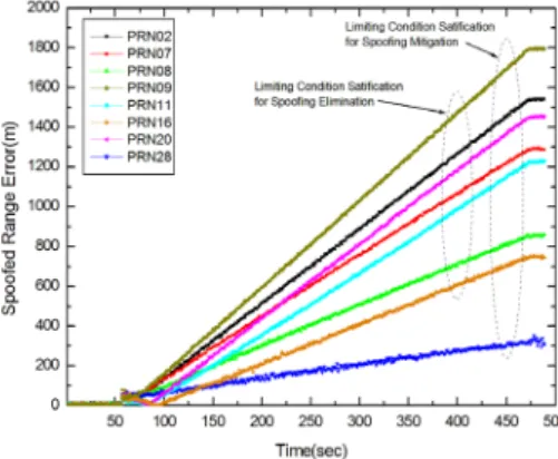
threshold. Thus, the GPS receiver can output the authentic navigation solution based on the authentic measures from the spoofing mitigation block. The navigation filter output can have integrity from the spoofing signals if the spoofing detection block operates well. However, the authentic navigation solution cannot be solved when fewer than four authentic measurements remain or the position dilution of precision (PDOP) is too high, i.e., the GPS navigation solution is not reliable. Since we focus on the performance evaluation system to verify the anti-spoofing equipment, we should consider the injected number of spoofing signals and the PDOP value obtained by the remaining authentic GPS signals as conditions of limitation for the performance evaluation. Since the performance evaluation should cover all mitigation algorithms, we set the threshold as 300 m, which is known as 1-chip range between an original GPS signal and its spoofing one in the spoofing injection scenario. The spoofing mitigation block of the developed anti-spoofing equipment has a lower threshold value than the threshold for the performance evaluation considering the operation environment.
The spoofing elimination block attempts to successively
eliminate the detected spoofing signal when a spoofing
signal power is higher than and equal to the threshold,
P
threshold, i.e., p
kSP≥ P
threshold. In order to eliminate the spoofing
signal, the spoofing elimination block should track a
spoofing signal and obtain raw measurements, which
include the carrier phase, code range, Doppler shift,
navigation data, and received power of the tracked
spoofing signal. Based on the raw measurements, the
spoofing elimination block generates a replica of the
tracked spoofing signal and successively cancels the
Fig. 1. Structure design of the anti-spoofing equipment.
spoofing signal using the antiphase replica before providing measurements to the authentic navigation solution. The spoofing elimination block can offer the spoofing-free measurements to the authentic navigation solution. Since the success of spoofing signal elimination relies on the precision of the raw measurements of the tracked spoofing signal, the ADC bit resolution holds on the original 16- bit instead of the quantized 2-bit. The 16-bit ADC, 20 MHz frequency sampled input data are connected to the spoofing elimination block. For the spoofing elimination block, there is the basic assumption that an original GPS signal is perfectly recovered after the spoofing elimination when the code range of the spoofing signal is far from that of the original one. Fig. 2 shows the limit condition of the performance evaluation for the spoofing elimination block. In Fig. 2, R(τ) denotes the auto-correlation function according to time delay τ. T
cand p are the 1-chip duration and signal power, respectively. As shown in Fig. 2, the code range between the spoofing signal and the original one should be further than 600 m, which is known as the 2-chip range. When the code range difference between the original and spoofing signals is less than the 2-chip range, the eliminated antiphase replica signal affects a part of the original GPS signal and the original one cannot be tracked or perfectly recovered. Since we focus on the performance evaluation system to verify the anti-spoofing equipment, we should guarantee that the code range difference between the original GPS signal and its spoofing signal is 600 m by the design of the spoofing injection scenario.
We have developed an anti-spoofing equipment based on the structure design in Fig. 1. The outline of the anti- spoofing antenna and equipment is shown in Fig. 3. We developed the anti-spoofing equipment as a part of the anti-jamming, anti-spoofing, and jammer position finding system in Fig. 3b. The anti-spoofing equipment is composed of a signal processing device, a RF assembly, and a power supply device. We developed the anti-spoofing equipment antenna with the 8-inch size to support the aforementioned anti-spoofing equipment.
3. PERFORMANCE EVALUATION TEST SYSTEM
We consider a spoofing injection simulator that should include a timing synchronization function and a navigation data matching function to the received authentic signals.
Based on the received authentic signals, the spoofing injection simulator should control the power and code phase of the generated spoofing signals. In order to automatically control the power and code phase, the spoofing injection simulator should acquire and track the GPS signals in real time. We select the SimSAFE software and hardware of SPIRENT Co. Ltd., which includes those functions as the spoofing injection simulator. The SimSAFE software was developed to generate the simulated spoofing signal and evaluate the performance of an anti-spoofing GPS receiver with a GPS simulator.
Since we evaluate the anti-spoofing equipment including its antenna, we should use a spoofing injection simulator as the spoofing signal emission equipment. Since the spoofing signal emission has a notably dangerous and critical issue when the signal is emitted to the air, the emission is regulated by the government. Thus, we must emit the simulated signal in a restricted environment such as an anechoic chamber and minimize the distance between the anti-spoofing equipment and the spoofing signal transmitting antenna considering the far-field condition.
Therefore, the spoofing signal is not emitted in air. The evaluation structure of the anechoic chamber with the spoofing injection simulator to evaluate the performance of the anti-spoofing GPS equipment is shown in Fig. 4.
In this paper, we do not focus on how to successfully inject a spoofing signal to GPS receivers, but we focus on how to successfully evaluate the anti-spoofing GPS equipment in the condition of synchronized spoofing signal injection to GPS signals. Thus, the spoofing signal injection scenarios should be considered to mitigate and eliminate the spoofing signals. In order to evaluate the performance Fig. 2. Limiting condition of the performance evaluation for the spoofing
elimination block. Fig. 3. Developed anti-spoofing equipment and antenna.
(a) Anti-spoofing antenna (b) Anti-spoofing equipment
Junwoo Jung et al. Dev. of Anti-Spoofing Equipment Arch. & Perf. Eval. Test System 131
of the anti-spoofing equipment, we design the spoofing injection scenario as shown in Fig. 5. We assume that all spoofing signals are generated and transmitted from a single source. The scenario should consider both spoofing mitigation and elimination algorithms. In this injection scenario, there is a rendezvous point to cross the position generated by the authentic and spoofing signals and the distance increases from the rendezvous point. In order to evaluate the spoofing detection, mitigation, and elimination blocks, we set different criteria for the range error thresholds as we mentioned in Section 2. For the spoofing mitigation algorithm, we set the threshold as 300 m (1-chip range) between an authentic GPS signal and its spoofing one. For
the elimination algorithm, we set the threshold as 600 m (2- chip range). The discrete code range between an authentic signal and its spoofing one can be changed according to the constellation of GPS satellites and spoofing insertion time.
To satisfy both requirements, we set the distance of the positions generated by authentic and spoofing signals as 2900 m based on Jung et al. (2016) and the position where spoofing signals stop. At the stop position, the spoofing signals continue injecting for data logging to calculate the horizontal error as the CEP of the anti-spoofing equipment.
We do not consider the vertical error, since the spoofing injection scenario is generated to move on the horizontal domain as shown in Fig. 5. As shown in Fig. 5, this spoofing Fig. 4. Evaluation structure of the anechoic chamber using a spoofing injection simulator to evalu-
ate the anti-spoofing equipment.
Fig. 5. Scenario of the spoofing injection simulator to evaluate the anti-spoofing equipment.
injection scenario has an advantage that the scenario can start to inject spoofing signals at any time, since the victim anti-spoofing equipment has a fixed position and the scenario has the fixed position as the rendezvous position.
4. EXPERIMENTAL RESULTS
We evaluate the performance of the anti-spoofing equipment in an anechoic chamber as shown in Fig. 6. In order to transmit GPS L1/L2 spoofing signals, we use the GPS L1/L2 spoofing injection simulator based on SimSAFE.
The performance evaluation test parameters and values are shown in Table 1. In the spoofing injection simulator, we set the GPS signal types as L1 C/A and L2C. In order to evaluate the anti-spoofing equipment, which includes the spoofing signal mitigation and elimination algorithms, we change the spoofing jam-to-signal power rate (J/S) from 10 dB to 20 dB when the received GPS signal power, which we calibrate, is -130 dBm. Since the anti-spoofing equipment selects between mitigation and elimination algorithms against spoofing signals based on the received signal power, we set all spoofing signal powers as -120 dBm or -110 dBm. We set the GPS spoofing transmit antenna with the incidence angle of 30°. According to the spoofing injection scenario in Section 2, we set the moving speed, moving distance, and operation time as 10 m/sec, 3 km, and 15 minutes, respectively. In this scenario, we set the rendezvous point as
100 m from the start position.
Based on the test parameters and values, we construct the test environment in the anechoic chamber as shown in Fig. 6. We assume that the GPS L1/L2 signal transmitting antennas constructed in the anechoic chamber satisfy the far-field condition for the independence of radio frequency on the magnetic frequency. In the test environment, we should consider satisfying the far-field condition of the distance between the anti-spoofing antenna and the spoofing signal transmitting directional antenna. The GPS and spoofing injection simulators generate signals of GPS L1 and L2 frequencies as 1575.42 MHz and 1227.6 MHz, respectively. Thus, the wave lengths, λ
L1of GPS L1 and λ
L2of L2 are 0.190 m and 0.244 m, respectively. The sizes of a patch of the anti-spoofing antenna and spoofing signal transmitting antenna are 0.203 m and 0.496 m, respectively.
For the GPS L1 and L2 frequencies, the distances that satisfy the far-field condition can be obtained by (Balanis 2015),
positions generated by authentic and spoofing signals as 2900 m based on Jung et al. (2016) and the position where spoofing signals stop. At the stop position, the spoofing signals continue injecting for data logging to calculate the horizontal error as the CEP of the anti-spoofing equipment. We do not consider the vertical error, since the spoofing injection scenario is generated to move on the horizontal domain as shown in Fig. 5. As shown in Fig. 5, this spoofing injection scenario has an advantage that the scenario can start to inject spoofing signals at any time, since the victim anti-spoofing equipment has a fixed position and the scenario has the fixed position as the rendezvous position.
4. EXPERIMENTAL RESULTS
We evaluate the performance of the anti-spoofing equipment in an anechoic chamber as shown in Fig. 6. In order to transmit GPS L1/L2 spoofing signals, we use the GPS L1/L2 spoofing injection simulator based on SimSAFE. The performance evaluation test parameters and values are shown in Table 1. In the spoofing injection simulator, we set the GPS signal types as L1 C/A and L2C. In order to evaluate the anti-spoofing equipment, which includes the spoofing signal mitigation and elimination algorithms, we change the spoofing jam-to-signal power rate (J/S) from 10 dB to 20 dB when the received GPS signal power, which we calibrate, is -130 dBm. Since the anti-spoofing equipment selects between mitigation and elimination algorithms against spoofing signals based on the received signal power, we set all spoofing signal powers as -120 dBm or -110 dBm. We set the GPS spoofing transmit antenna with the incidence angle of 30°. According to the spoofing injection scenario in Section 2, we set the moving speed, moving distance, and operation time as 10 m/sec, 3 km, and 15 minutes, respectively. In this scenario, we set the rendezvous point as 100 m from the start position.
Based on the test parameters and values, we construct the test environment in the anechoic chamber as shown in Fig. 6. We assume that the GPS L1/L2 signal transmitting antennas constructed in the anechoic chamber satisfy the far-field condition for the independence of radio frequency on the magnetic frequency. In the test environment, we should consider satisfying the far-field condition of the distance between the anti-spoofing antenna and the spoofing signal transmitting directional antenna. The GPS and spoofing injection simulators generate signals of GPS L1 and L2 frequencies as 1575.42 MHz and 1227.6 MHz, respectively. Thus, the wave lengths, λ
L1of GPS L1 and λ
L2of L2 are 0.190 m and 0.244 m, respectively. The sizes of a patch of the anti-spoofing antenna and spoofing signal transmitting antenna are 0.203 m and 0.496 m, respectively. For the GPS L1 and L2 frequencies, the distances that satisfy the far-field condition can be obtained by (Balanis 2015),
2
2, 1 2
Lf Lf
d D Lf L or L (2)
where D denotes the size of the antenna, and λ
Lfdenotes the wave-length of the transmitting signal for frequency Lf. D is determined by the largest antenna size between transmit and receive antennas, D = 0.496 m. Based on Eq. (2), we obtain d
L1= 2.589 m and d
L2= 2.016 m and we set the distance between the anti-spoofing antenna and the spoofing signal transmitting directional antenna as 3 m.
Fig. 7 shows an example of the GPS satellite constellation at the start time of a spoofing injection scenario to evaluate the performance of the anti-spoofing equipment. In the spoofing
(2)
where D denotes the size of the antenna, and λ
Lfdenotes the wave-length of the transmitting signal for frequency Lf. D is determined by the largest antenna size between transmit and receive antennas, D = 0.496 m. Based on Eq.
(2), we obtain d
L1= 2.589 m and d
L2= 2.016 m and we set the distance between the anti-spoofing antenna and the spoofing signal transmitting directional antenna as 3 m.
Fig. 7 shows an example of the GPS satellite constellation at the start time of a spoofing injection scenario to evaluate the performance of the anti-spoofing equipment. In the spoofing injection scenario, the spoofing injection simulator can generate at most 8 satellites and maintain the generated spoofing signals at the end of the scenario. The set of spoofing GPS satellites can be changed according to the scenario.
Table 1. Performance evaluation test parameters and values.
Parameters Values
GPS signal type
Received GPS signal power Received spoofing signal power Spoofing jam-to-signal power ratio (J/S) Incidence angle of spoofing signal Moving speed in spoofing scenario Moving distance in spoofing scenario Operation time in spoofing scenario
L1 CA / L2C -130 dBm
-120 dBm / -110 dBm 10 dB / 20 dB 30°
10 m/sec 3000 m 15 minutes