Vol.19, No.3, (2017), pp.1~7 https://doi.org/10.9714/psac.2017.19.3.001
```
1. INTRODUCTION
The problem of CO2 emission that will seriously influence environment of the earth must be solved as soon as possible by shifting from steam power energy to renewable energy. If the generation and consumption of the electric power are done in a closed narrow region, however, installation of energy storage system is necessary when the generated electric power is greater. If a superconducting DC power network can be constructed over a wide region, people do not need expensive energy storage systems, since excess electric power can be immediately transferred to a region where the electric power is short. The superconducting network itself is also beneficial from the viewpoint of energy dissipation.
In this case the high cost of superconducting tapes is a big problem. Development of high critical current has been strongly conducted to reduce the cost per unit current.
However, appreciable improvement of the critical current has not been obtained.
The performance of usual superconducting devices depends on the critical current of used superconductor and it does not change when the same superconductor is used.
However, it is known that the critical current can be dramatically increased by application of parallel magnetic field in comparison with the case in the perpendicular magnetic field as shown in Fig. 1 [1]. This is called the longitudinal magnetic field effect. In this field configuration the force-free state, i..e., the state in which the current flows locally parallel to flux lines, is attained [2].
The outer shield conductor that carries the return current is twisted helically to apply a longitudinal magnetic field to
the inner conductor. If the superconductor of the inner conductor is properly wound in such a way that the force-free state is achieved, the current-carrying capacity can be shown to be dramatically enhanced in comparison with usual superconducting DC cables even when the same superconductor is used [3].
However, the critical current density in commercial coated conductors does not increase in the parallel magnetic field. In this case the current-carrying capacity does not increase in comparison with usual cables even if the force-free state is achieved, since the efficiency of transport current decreases because of helical winding of superconducting tapes. Nevertheless, the critical current density in the longitudinal magnetic field is appreciably
Development of innovative superconducting DC power cable
Teruo Matsushita* and Masaru Kiuchi
Department of Computer Science and Electronics Kyushu Institute of Technology, Iizuka, Japan (Received 11 September 2017; revised or reviewed 17 September 2017; 18 September 2017)
Abstract
It is required to reduce the cost of superconducting cable to realize a superconducting DC power network that covers a wide area in order to utilize renewable energy. In this paper a new concept of innovative cable is introduced that can enhance the current-carrying capacity even though the same superconducting tape is used. Such a cable can be realized by designing an optimal winding structure in such a way that the angle between the tape and magnetic field becomes small. This idea was confirmed by preliminary experiments for a single layer model cable made of Bi-2223 tapes and REBCO coated conductors. Experiments of three and four layer cables of practical sizes were also done and it was found that the current-carrying capacity increased as theoretically predicted. If the critical current properties of commercial superconducting tapes are further improved in a parallel magnetic field, the enhancement will become pronounced and this technology will surely contribute to realization of superconducting DC power network.
Keywords: superconducting DC cable, current-carrying capacity, longitudinal magnetic field effect
* Corresponding author: [email protected] Fig. 1. Critical current of superconducting Nb3Sn tape in the transverse (○) and parallel (●) magnetic fields [1].
higher than that in the transverse magnetic field. If this superior property in the parallel magnetic field is used in a suitable way, there is a room for appreciable enhancement of the current-carrying capacity [4, 5]. In this article an innovative superconducting DC cable is introduced in which the winding structure of the superconductor is optimized for the current-carrying capacity. Preliminary experimental results that promise realization of such a cable are reported. Recent research of superconducting tapes that show enhancement of the critical current density is also introduced. If such a coated conductor can be produced in the future, it is possible to realize the force-free cable with high current-carrying capacity.
2. INNOVATIVE SUPERCONDUCTING CABLE 2.1. Analytic Model
In this section the analysis for the optimization of the winding structure of the inner conductor of the cable is discussed [4]. We assume a former of the inner conductor of radius R0 on which n layers of superconducting tapes are wound. The thickness of the superconducting tape is denoted by d. Then, the radius of the i -th layer from the most inner layer is Ri=R0+id. The winging angle of the i-th layer is assume as
(1) (1) as schematically illustrated in Fig. 2. The field angle
dependence of the critical current density is necessary for designing the structure of the cable. Here the critical current densities in the in-plane transverse magnetic field and parallel magnetic field are denoted by Jcm and JcM, respectively. For numerical analysis the magnetic field dependence of these critical current densities is
approximated by polynomials such as . B K J
, B K
J j
j j j
j
j
∑
∑
= ==
= 9
0 M
cM 9
0 m
cm (2)
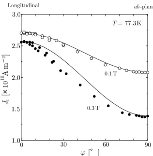
Figure 3(a) and (b) is an example that shows good agreements with observed results for these critical current densities. The dependence of the critical current density on the in-plane field angle ϕ measured from the tape axis is approximated as
(3) which agrees with experimental results in the low magnetic field region realized in practical superconducting cables as shown in Fig. 4. Then, the critical current of the i-th layer is (4) where Jci is the critical current density of the i-th layer and t is the thickness of the superconducting layer of the tape.
Here we estimate the current-carrying capacity of the cable. Hence, it is assumed that the critical current flows in each layer. The axial magnetic field produced by the return current in the outside shield conductor is denoted by Bext. Since the axial and azimuthal components of the current produce the azimuthal and axial field components in the outside and inside of the layer, respectively. Hence, the axial and azimuthal components of magnetic field on the i-th layer are:
(5) Fig. 2. Schematic illustration of the winding structure of (6)
the superconducting layers in the inner conductor.
( ) ,
n i
i 2 m
1
2 θ
θ = −
( ) ( ) ( )cos2 ,
2 1 2
1
cm cM cm
cM
cϕ J J J J ϕ
J = + + −
,t J R Ii=2π i ci
R ,
B i I k
k i
i k θ
π µ cos 2
1 1 n
∑
− 0=
=
∑
=++
= n
i k
k k
i k B ,
R B I
1 0 ext
p sin
2 θ
π µ
Fig. 3. Critical current densities of REBCO coated conductor in the transverse (○) and parallel (●) magnetic fields [5].
B . B
i i i
i tan-1 pn
−
=θ ϕ
∑
== n
i
i
i .
I I
1
c cosθ
( ) ( )
[ ]
( ) ( )
[ i i ] i
i i
i
J J
J J
J
ϕ ϕ
ϕ ϕ ϕ
2 cos2 1
2 1
cm cM
cm cM
c
− + +
=
( )
∑
==
=
= n
i
i
i B , / ,
I I
1 ext
0 0ϕ π 2
respectively. Then, the magnitude and angle from the superconducting tape of the magnetic field on the i-th layer are:
(7)
(8) Then, the critical current density of the i-th layer is
(9)
and the current-carrying capacity of the cable is given by (10) We have n sets of Eqs. (9) and these can be solved numerically using iteration method with initial condition such as
(11) In comparison the current-carrying capacity of usual superconducting cable is approximately given by
(12) although this is an overestimate because of the assumption of θi = 0.
2.2. Results of Numerical Calculation
Figure 5 shows the results of the current-carrying capacity vs. θm in various values of Bext for n = 8, R0 = 20
mm mm, d = 200 μm and t= 2.0μm, where the critical current densities in Figs. 3 and 4 are assumed. The value at θm = 0 and Bext = 0 shown by the circle gives the current-carrying capacity Ic0 of the corresponding usual cable of the same size. The current-carrying capacity increases with θm and reaches a maximum value accompanied by a decrease. The initial increase is caused by application of the longitudinal self-field. The decrease at large θm values is caused by a reduction in the transport efficiency proportional to cosθi. The peak value of the current-carrying capacity increases with increasing Bext and reaches the maximum at around 0.30 T. This increase is attributed to the enhancement of the critical current density from Jcm in the longitudinal magnetic field. The reduction in the peak value for a larger Bext comes from a weak magnetic field dependence of Jc. It is found that the current-carrying capacity can be enhanced in a wide range of θm and Bext from the usual cable. The peak value of Ic for each Bext value is denoted by Icm. Now the enhancement factor of current-carrying capacity is defined by
(13) Figure 6 shows the enhancement factor vs. Bext for various n values. It is found that the enhancement factor increases with Bext and reaches a maximum for each n value and the maximum value increases with n.
It should be noted that Bext cannot be enhanced independently but there is attainable value, since Bext is produced by a return current flowing in the shield conductor. The mean radius and twisting angle of the shield conductor are denoted by Rs and θs. Since the same current Ic flows in the shield conductor in the critical state, the
( ) ( )
B B ,Bi i i /
2 2 1 2 n
p
+
=
(B ). J
J J
Jc1(0) = c2(0) == cn(0) = cM =0
. I Icm c0 η=
Fig. 4. In-plane magnetic field angle dependence of critical current density at 0.1 and 0.3 T [5]. The solid lines show Eq. (3).
Fig. 5. Current-carrying capacity vs. θm in various values of external longitudinal magnetic field Bext for n=8 [5]. The circle shows to the current-carrying capacity of usual cable of the same size.
R .
B I s
s c
extm 0 tan
2 θ
π
= µ
longitudinal magnetic field produced by this current, i.e., the maximum value of Bext, is given by
(14) If we assume as Rs = 25 mm and θs = 40 °, the attainable enhancement factor is shown in Fig. 7 [5]. When the layer number increases, the attainable value of Bext increases and the enhancement factor increases.
This indicates us that, even if the longitudinal magnetic field effect is not improved, the enhancement factor can be improved through the enhancement of Bextm when the value
of the critical current density is improved. Figure 8(a) and (b) shows the variation in the enhancement factor when the Jc(B) values are simply improved by factor of 1.5 and 2.0, respectively [5]. It is found that the enhancement factor is really predicted to be improved through the improvement of Jc(B). Thus, the present innovative superconducting power cable is promising.
3. EXPERIMENTS 3.1 Preliminary investigation
A simple simulation measurement of short single layer cable was examined. Figure 9(a) and (b) shows a cable
(a)
(b)
Fig. 8. Enhancement factor vs. external longitudinal magnetic field when the critical current density is simply improved by factors of (a) 1.5 and (b) 2.0 [5].
Fig. 6. Enhancement factor of current-carrying capacity vs.
Bext for various n values [5].
Fig. 7. Enhancement factor current-carrying capacity vs.
external longitudinal magnetic field. The solid lines show attainable regions and the open symbols show the optimal conditions for each layer number [5].
twisted by 19 and a straight cable made of SuperPower REBCO coated conductors of about 4 mm in width. The number of tapes for these cables was 14 and wound on a bobbin of 18 mm in diameter. The longitudinal magnetic field was applied using a superconducting magnet. Figure 10 shows the longitudinal magnetic field dependence of the critical current of these cables. It is found that the critical current has a peak at around 38 mT for the twisted cable, while that decreases monotonically with increasing magnetic field for the straight cable. The peak critical current is improved by 14.8% in comparison of the critical current of the straight cable in the absence of the magnetic field. Since the peak critical current is 1.66 kA, the transverse magnetic field in this condition is 31 mT. Hence, the angle of the magnetic field on the outer surface of the tape is 39.2 . It means that the field angle of the center of the tape is 18.6 , which is quite close to the twisting angle.
Thus, the situation close to the force-free state was achieved at the peak condition. On the other hand, the critical currents of these cables cross at around 0.2 T.
Above this magnetic field the difference of angle between the total magnetic field and winding direction is smaller for the straight winding. This also indicates that the field angle
is important in determination of the critical current. A similar improvement of the critical current by twisting was obtained for Bi-2223 tapes [6]. These preliminary investigations show that the proposed structure is effective to enhance the current-carrying capacity also in the practical power cable.
3.2 Experiments of Practical Scale
Based on the results of preliminary investigation a four layer cable was constructed with Bi-2223 tapes. The diameter of the former was 18.0 mm and the twisting angle of these layers was simply set as 10 for simplicity, since the optimum value was small. The number of tapes for the innermost to the outer layers was 11, 12, 13 and 13. The longitudinal magnetic field was applied by the outer conductor. The inner and outer conductors were driven separately to investigate the magnetic field dependence in detail. Figure 11 shows the current-carrying capacity of the four layer cable vs. the current to the outer conductor where
Current (A) 𝐼𝐼c
(A)
Fig. 11. Current-carrying capacity of four layer cable made of Bi-2223 tapes vs. the current applied to the outer conductor.
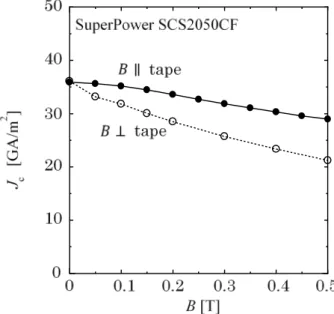
Fig. 12. Magnetic field angle dependence of the critical current density of SuperPower tape.
(a)
(b)
Fig. 9. (a) Single layer cable twisted by 19 and (b) a straight cable made of SuperPower REBCO coated conductors.
0 0.5
1000 1500
Bext, T Ic, A
0 degree 14 tapes cable 19 degree 14 tapes cable
Fig. 10. Critical current vs. longitudinal magnetic field for single layer cables in Fig. 9.
the longitudinal magnetic field produced by the external current of 100 A is 54 mT. Although the enhancement of the current-carrying capacity is not so large, it continues to increase up to 190 A (103mT) or more. Thus, the principle of the improvement by the longitudinal magnetic field is effective also for Bi-2223 tapes.
The inner conductor of a three layer cable was constructed with a SuperPower tape of 2 mm wide. The magnetic field angle dependence of the critical current density of this tape is shown in Fig. 12. The diameter of the former was 10 mm and the number of tapes used for the inner, middle and outer layers were 13, 14 and 14, respectively. The twisting angle of these layers was simply designed as 10 because of the same reason for the Bi-tape cable. The structure of the inner conductor is schematically shown in Fig. 13. The longitudinal magnetic field was applied by a superconducting magnet. The current-carrying capacity normalized by the value (3.00 kA) in the absence of the field is shown as a function of the magnetic field in Fig. 14 [10]. The observed current-carrying capacity was smaller by about 10 % than the theoretical prediction because the surface area of each layer was not fully covered with the superconducting tapes and there were gaps between adjacent tapes. It is found from the figure that the predicted magnetic field dependence agrees well with the experiments and the current-carrying capacity is maximum at about 0.1 T.
4. DISCUSSION
From Figs. 11 and 14 the proposed scheme is useful to enhance the current-carrying capacity of the cable even though the same superconducting tape is used.
One of the outstanding points of this scheme is that the theoretical analysis is not so difficult and the prediction fits well with the experiments. However, the enhancement is not appreciable, since the number of layers is limited. For cables with a larger current-carrying capacity, the merit of the proposed scheme is expected to be pronounced. In addition, if the critical current density of the tape can be increased by improving the fabrication technique, a larger enhancement will be achieved through the increase in Bextm.
The largest problem in realizing the ideal cable is the lack of increase in the critical current density with increasing longitudinal magnetic field as shown in Figs.
3 and 12. The reason for the poor critical current density of present commercial coated conductors in the longitudinal magnetic field is speculated to be a growth of a or tilted c-axis grains the grain boundaries of which make the transport current meander [7], resulting a deviation from the force-free state.
However, recently fabrication of coated conductors with enhanced critical current density in the longitudinal magnetic field was succeeded by introducing suitable artificial pinning centers [8, 9].
Figure 15 shows an example of enhanced critical current density [9]. If commercial coated conductors with such a property are fabricated in the future, it is expected that a significant enhancement of the current-carrying capacity is achieved. Then, the current-carrying capacity is theoretically estimated as a function of the longitudinal magnetic field when a three layer cable of the same size is fabricated with the coated conductor shown in Fig. 15. The result in Fig.
16 shows a dramatically improved property. If the number of layers is increased, such a large current-carrying capacity is expected to be realized through the enhancement of longitudinal magnetic field that the cable itself produces.
If such a large enhancement of the current-carrying capacity is obtained, it is possible to introduce a fault-current limiting function to the power cable itself [11]. That is, if the cupper stabilizer is wound in the opposite directions to the superconducting tapes in the inner and shielding conductors, the excess current that flows in the copper stabilizer reduces the longitudinal magnetic field, resulting in reduction in the current-carrying capacity. This will accelerate the resistive transition of the cable and limit the current when a large accidental current comes in. The introduction of the fault-current limiting function to the cable itself will contribute to a further reduction in the coast of superconducting DC power network. This will be helpful for achieving this network.
Fig. 13. Schematic illustration of the structure of the inner conductor.
−0.4 −0.3 −0.2 −0.1 0 0.1 0.2 0.3 0.4 0.5 0.7
0.8 0.9 1 1.1
B [T]
Ict / Ict(0)
T = 77.3 K
−0.5
exp.
ana.
Fig. 14. Experimental (symbols) and analytical (broken line) results of the current-carrying capacity normalized by the self-field value [10].
5. SUMMARY
The concept of innovative force-free cable is introduced.
Unfortunately the present commercial coated conductors do not show an enhancement of the critical current density by applying a parallel magnetic field. Nevertheless the current-carrying capacity of the cable can be appreciably enhanced from that of existing types of cable by employing a suitable winding structure of superconducting tapes in the cable. This was experimentally confirmed for Bi-2223 and REBCO superconductors.
Recently the critical current density was successfully
enhanced in the parallel magnetic field in some short REBCO samples. This indicates that commercial coated conductors with such a good property will be fabricated by introducing proper artificial pinning centers in the near future. In this case the force-free cable with dramatically enhanced current-carrying capacity will be realized.
Another merit of this cable is a fault-current limiting function of the cable itself that can be achieved by introduction of a suitable structure for the copper stabilizer.
Thus, these points are expected to contribute to the reduction in the cost of superconducting DC power network without expensive fault-current limiters.
REFERENCES
[1] G. W. Cullen and R. L. Novak, “Effect of Fast-Neutron-Induced Defects on the Current Carrying Behavior of Superconducting Nb3Sn,” Appl. Phys. Lett., vol. 4, pp. 147-149, 1964.
[2] D. G. Walmsley, “Force-Free Magnetic Fields in a Type II Superconducting Cylinder,” J. Phys. F, vol. 2, pp. 510-528, 1978.
[3] T, Matsushita, M. Kiuchi and E. S. Otabe, “Innovative Superconducting Force-Free Cable Concept,” Supercond. Sci.
Technol., vol. 25, pp. 125009, 2012.
[4] V. S. Vyatkin, K. Tanabe, J. Wada, M. Kiuchi, E. S. Otabe and T.
Matsushita, “Calculation of Critical Current in DC HTS Cable Using Longitudinal Magnetic Field Effect,” Physica C, vol. 494, pp.
135-139, 2013.
[5] V. S. Vyatkin, M. Kiuchi, E. S. Otabe and T. Matsushita, “Design of Practical Superconducting DC Power Cable with REBCO Coated Conductors,” IEEE Trans. Appl. Supercond., vol. 25, pp.
6606207, 2015.
[6] V. S. Vyatkin, M. Kiuchi, E. S. Otabe, M. Ohya and T. Matsushita,
“Current-Carrying Capacity of Single Layer Cable Using Superconducting Bi-2223 Tapes in a Parallel Magnetic Field,”
Supercond. Sci. Technol., vol. 28, pp. 015011, 2015.
[7] T. Kato, R. Yoshihara, N. Chikumoto, S. Lee, K. Tanabe, T. Izumi, T. Hirayama and Y. Shiohara, “Microstructure Characterization of GdBa2Cu3Oy Superconductive Layer Fabricated by In-Plume Laser Deposition,” Physica C, vol. 471, pp. 1012-1016, 2011.
[8] A. Tsuruta, S. Watanabe, Y. Ichino and Y. Yoshida, “Enhancement of critical current density in the force-free sate of BaHfO3-doped multilayered SmBa2Cu3Oy film,” Jpn. J. Appl. Phys., vol. 53, pp.
078003, 2014..
[9] R. Kido, M. Kiuchi, E. S. Otabe, T. Matsushita, A. K. Jha and K.
Matsumoto, “Critical Current Properties in Longitudinal Magnetic Field of YBCO Superconductor with APC,” Phys. Procedia, vol. 81, pp. 117-120, 2016.
[10] M. Kiuchi, R.Kido, Y. Tanabe, E. S. Otabe, T. Matsushita, M. Yagi and H. Fukushima, to be published.
[11] T. Matsushita, M. Kiuchi, E. S. Otabe and V. S. Vyatkin,
“Fault-Current Limiting Properties in Innovative Force-Free Superconducting DC Cable,” IEEE Trans. Appl. Supercond., vol.
25, pp. 5401704, 2015.
0 0.1 0.2 0.3 0.4 0.5
0 20 40 60 80
Jc [GA/m2 ]
B[T]
B//I , B//ab B⊥I , B//ab PLD
CVD CVD PLD
Fig. 15. Magnetic field dependence of critical current density in PLD processed coated conductor with artificial pinning centers [9]. The properties of SuperPower tape in Fig. 12 are also shown for comparison.
0 0.1 0.2 0.3 0.4 0.5
2000 4000 6000
B [T]
Ic [A]
PLD
CVD
Fig. 16. Theoretically expected current-carrying capacity vs. longitudinal magnetic field for three layer cable of the same size made of coated conductors shown in Fig. 15 [10]. The theoretical estimation of the current-carrying capacity in Fig. 14 is also shown for comparison.
![Fig. 3. Critical current densities of REBCO coated conductor in the transverse (○) and parallel (●) magnetic fields [5]](https://thumb-ap.123doks.com/thumbv2/123dokinfo/5237294.623940/2.892.469.782.120.423/critical-current-densities-rebco-conductor-transverse-parallel-magnetic.webp)
![Fig. 8. Enhancement factor vs. external longitudinal magnetic field when the critical current density is simply improved by factors of (a) 1.5 and (b) 2.0 [5]](https://thumb-ap.123doks.com/thumbv2/123dokinfo/5237294.623940/4.892.100.422.118.436/enhancement-external-longitudinal-magnetic-critical-current-density-improved.webp)
![Fig. 13. Schematic illustration of the structure of the inner conductor. −0.4 −0.3 −0.2 −0.1 0 0.1 0.2 0.3 0.4 0.50.70.80.911.1 B [T]Ict / Ict(0) T = 77.3 K−0.5exp.ana.](https://thumb-ap.123doks.com/thumbv2/123dokinfo/5237294.623940/6.892.90.432.853.1076/fig-schematic-illustration-structure-inner-conductor-ict-ict.webp)
![Fig. 15. Magnetic field dependence of critical current density in PLD processed coated conductor with artificial pinning centers [9]](https://thumb-ap.123doks.com/thumbv2/123dokinfo/5237294.623940/7.892.113.413.115.418/magnetic-dependence-critical-current-density-processed-conductor-artificial.webp)