a개원의.
b부교수, c조교수, d교수, 연세대학교 치과대학 교정학교실.
교신저자: 박영철.
서울시 서대문구 성산로 250 연세대학교 치과대학 교정학교실.
02-2228-3103; e-mail, [email protected].
원고접수일: 2010년 11월 24일 / 원고최종수정일: 2011년 5월 10일 / 원고채택일: 2011년 5월 13일.
http://dx.doi.org/10.4041/kjod.2011.41.5.324
*본 연구는 연세대학교 치과대학 두개안면기형연구소의 연구비에 의해 수행 됨.
Lingual sliding mechanics의 lever arm 효과에 대한 유한요소분석
김경희
a
ㆍ이기준b
ㆍ차정열c
ㆍ박영철d
전치의 후방 견인 시 적절한 치아 이동 상태 조절은 필수적이다. 설측 장치를 이용한 레버 암 길이의 조절을 통하여 치아 이동에 관한 연구는 있었으나 3차원적인 변위 양상에 대한 연구는 많이 이루어지지 않은 실정이다. 이에 본 연구는 상악 전치부의 레버 암(lever arm)의 길이를 5 mm 단위로 20 mm까지 증가시켰으며 대구치와 TPA (trans palatal arch) 상에 있는 견인 훅(hook)의 위치를 달리 하여 200 gm의 후방 견인력을 가했을 때 나타나는 치아 변위 양상과 응력분포를 3차원적 유한요소분석을 통하여 알아보고자 하였다. 이를 위하여 아시아 성인의 표본조사를 통해 제작된 치아모형(Nissan Dental Product, Kyoto, Japan)을 3차원적으로 스캐닝한 후 상악치아, 치주인대, 치조골에 대한 유한요소 모델을 제작하였다. 각 치아의 절단연과 치근첨의 이동량을 x, y, z 좌표에서 각각 계산하여 치열의 변위 양상을 분석하고 von Mises 응력 분포를 계측하였다. 연구 결과, 정상 교합 모형의 레버 암 길이가 15 mm, 20 mm인 경우 전치 절단연과 치근첨의 설측 변위가 유도되었다. 본 실험의 조건 중 20 mm에서 치근첨의 설측 변위 는 최대로 나타났다. 구치부 견인 훅이 치근첨에 있을 때 대구치 치관은 원심 방향으로 변위되었다. 또한 레버 암의 길이가 20 mm인 경우 전치부의 정출은 미약하였고 견치 치관은 협측 방향으로 전위되었다. 이 때 구치부 견인 훅의 위치가 TPA의 구개 중앙 측에 있을 때보다 가장자리 측에 있을 때 견치 치관은 더 많이 전위되었다. 이상의 결과를 토대로 설측 장치를 이용한 상악 6전치의 후방 견인 시 레버 암의 길이가 길고 구치부 견인 훅의 위치가 구개 중앙부 에 있을 때 전치부 절단연(incisal edge)의 정출 없이 견치의 측방 전위 및 전치부 절단연과 치근첨의 설측 변위가 공히 나타남을 알 수 있었다. (대치교정지 2011;41(5):324-336)
주요 단어: 설측교정, 슬라이딩 메카닉스, 레버 암, 유한요소분석
서론
발치공간의 폐쇄를 위하여 상하악 전치부의 후방 견인을 시행하는 경우 치료목적에 맞게 적절한 양 상의 치아이동을 하는 것이 필요하다. 전치부의 후 방 이동은 전치의 돌출 정도와 초기치축에 따라 비 조절성/조절성 경사이동, 치체이동 및 치근이동 등
다양한 형태로 이루어질 수 있으며 이를 위해 후방 견인력과 함께 적절한 압하력과 모멘트의 조절을 통한 치근 위치의 조절이 수반되어야 한다.
설측 장치를 이용한1 전치부의 후방견인 시 후방 견인력 및 압하력을 공히 적용하였을 때 순측 장치 를 이용한 경우보다 더 많은 전치부의 설측 경사를 보이지만 이를 방지하기 위해 설측 치근 토오크와 수직 방향의 압하력을 증가시키고 수평 방향의 견 인력을 감소시켜야 한다고 보고했다. 그러나 전치 부 호선에 토오크를 부여하는 것은 기술적으로 용 이하지 않으며 이러한 문제점을 해결하기 위한 방 법의 하나로 구치부의 transpalatal arch (TPA)와 전 치부의 레버 암을 이용한 lever arm mechanics2가 소 개된 바 있다. Park 등3은 전치부와 구치부의 비슷 한 이동이 필요한 경우 전치부와 구치부의 저항중 심을 지나도록 하고, 전치부의 후방견인을 최대로 하기 위해서는 구치부의 치근이동, 전치부의 조절
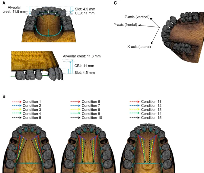
Fig 1. A, Three-dimensional finite element model for upper teeth, periodontal ligaments and alveolar bones; B, ex- perimental groups are divided into three groups depending on the position of retraction: position of retraction arm in the first group is placed at the bracket of the 2nd molar, at the furcation of the 2nd molar in the second group and at the root apex of the 2nd molar in the third group; C, the coordinate system is composed of X-axis, Y-axis and Z-axis. The origin of coordinate axes is the middle point of the incisal surface which connects with the upper right and left incisors. X-axis is the bucco-palatal direction (lingual (+), buccal (-)); Y-axis is the antero-posterior di- rection (anterior (+), posterior (-)); Z-axis is the superior-inferior direction (superior (+), inferior direction (-)). CEJ, Cemento enamel junction.
성 경사이동이 일어나도록 레버 암의 길이는 짧고 TPA 상의 훅의 위치는 구치의 치근첨 위치에서 후 방견인력을 가하는 것이 바람직하다고 하였다. 그 러나 레버 암의 길이에 따른 전치부의 이동양상4은 구치부의 anchor의 크기와 방향에 따라 많은 차이가 생길 것으로 생각되어 이에 대한 역학적인 연구가 필요하다.
치아 혹은 치아군에 역학적 힘체계를 적용하였을
때 발생하는 응력 및 생물학적 영향에 대한 분석을 위하여 광탄성법(photoelasticity method),5 laser holog- raphy method,6 스트레인게이지 측정법(electrical re- sistance strain-gauge method),7 유한요소법(finite ele- ment method)8 등이 많이 이용되어 왔다.
이 중 유한요소법은 실제와 같은 형태의 3차원 모델을 컴퓨터 상에서 제작하고 분석하는 공학적 수치 방법으로 초기 치아 이동 양상에 대한 변위,
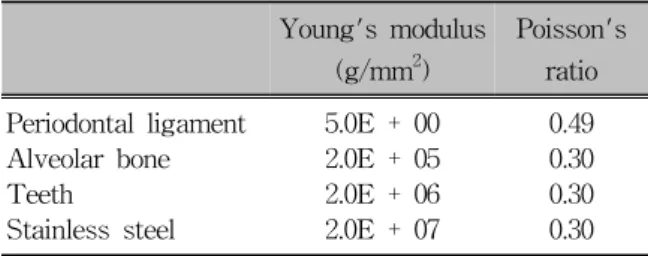
Table 1. Material properties
Young's modulus (g/mm
2)
Poisson's ratio Periodontal ligament 5.0E + 00 0.49
Alveolar bone 2.0E + 05 0.30
Teeth 2.0E + 06 0.30
Stainless steel 2.0E + 07 0.30
응력, 모멘트 값을 3차원 상에서 정량적으로 분석하고 그래픽으로 결과를 표시할 수 있으므로 치의학 연구 분야에 많이 이용되고 있다. 또한 기하학적인 형상, 하중 및 경계조건에 제한이 없으며 여러 재료 로 이루어진 연속체에서도 적용이 가능하고 모델 내부 특정부분을 다양한 각도와 단면에서 관찰할 수 있다는 장점이 있다.9
본 연구는 설측교정 치료 시 상악에서 제1소구치 를 발거하고 전치부의 레버 암의 길이와 구치부의 견인 훅의 위치를 다르게 하여 6전치를 후방 견인 하는 경우에 나타나는 전치부 및 구치부 치조골에 서의 초기 응력 분포와 치아변위 양상을 3차원적 유한요소법을 통하여 알아보고자 하였다.
연구방법
유한요소 모델의 제작 치아, 치근막과 치조골
아시아 성인의 표본조사를 통해 제작된 치아모형 (Nissan Dental Product, Kyoto, Japan)을 대상으로 하 여 3차원 스캐닝하여 제작하였다. 치열궁 형태는 Ormco 사의 broad arch form (Ormco, Orange, CA, USA)에 맞게 배열하였으며 각 치아의 inclination 및 angulation은 Andrews prescription10을 적용하였다. 치 근막의 두께는 Coolidge,11 Kronfeld12의 연구를 참고 로 0.25 mm로 균일하게 모형화하였으며 치조골은 정상적인 상태로 가정하여 cemento enamel junction (CEJ) 하방 1 mm 높이에서 CEJ 굴곡을 따라 형성 하였다. 모델에서 교합면에 수직으로 상악 중절치 의 절단연에서 브라켓 슬롯까지의 거리는 4.5 mm, CEJ까지의 거리는 11 mm이며 치조정까지의 거리 는 11.8 mm로 계측되었다 (Fig 1A).
브라켓, 주호선 및 lever arm
브라켓은 Ormco사의 7 generation 0.018 × 0.025 설측 브라켓(Ormco, Orange, CA, USA)을 적용하였 고, Andrews13의 정의에 따라 각 치아의 순측 치관 중점인 facial axis (FA) point를 표시한 후 이를 연결 한 Andrew's plain과 평행하면서 설측 임상 치관의 FA point를 지나는 평면에 브라켓 슬롯이 위치하도 록 개개 치아에 부착하였다. 주호선은 0.016" × 0.022" 스테인레스 스틸 호선을 사용하였고 호선과
브라켓 사이의 경계조건은 불필요한 wire-bracket play를 방지하기 위해 슬롯과 호선상에 유격을 부여 하지 않은 채 마찰 없이 슬라이딩이 가능하도록 설 정하였다. 측절치와 견치 사이의 레버 암은 0.7 mm, 대구치 사이의 TPA는 힘 적용 시 변형되지 않도록 0.9 mm 스테인레스 스틸 호선으로 하였다.
Mechanical property
본 연구는 교정력이라는 약한 힘을 가했을 때 나 타나는 초기 반응을 알아보고자 하였으므로 치아, 치조골, 치근막과 선재는 등방(isotropy), 등질(homo- geneity)의 선형 탄성체(linear elasticity)로 가정하였 고 구성치조들의 물성치는 Cook 등,14 Tanne 등15과 Sung 등16의 연구를 참고로 하여 Young's modulus 와 Poisson's ratio를 부여하였다 (Table 1).
실험 방법 및 유한요소 해석 실험 방법
Lever arm mechanics는 전치부의 레버 암과 구치 부에 교정력을 가할 수 있는 hook이 부착된 TPA 로 구성되어 있다. 레버 암의 위치는 측절치와 견치사 이이며, 레버 암의 각도는 교합평면에 대하여 45도 로 설정하였고, 전치부 후방 견인력은 Bennett과 McLaughlin17이 제시하는 편측당 200 gm로 정하였 으며, 후방 견인력은 호선이 후방으로 빠져나가는 방향으로 설정하였다 (Fig 1B).
유한요소 해석
힘 체계의 분석을 위해 미국 Swanson Analysis System 사의 범용유한요소해석 프로그램인 ANSYS version 11.0 (ANSYS, Canonsburg, PA, USA)을 사용 하였다. 모델의 제작에 사용된 요소의 형태는 사면
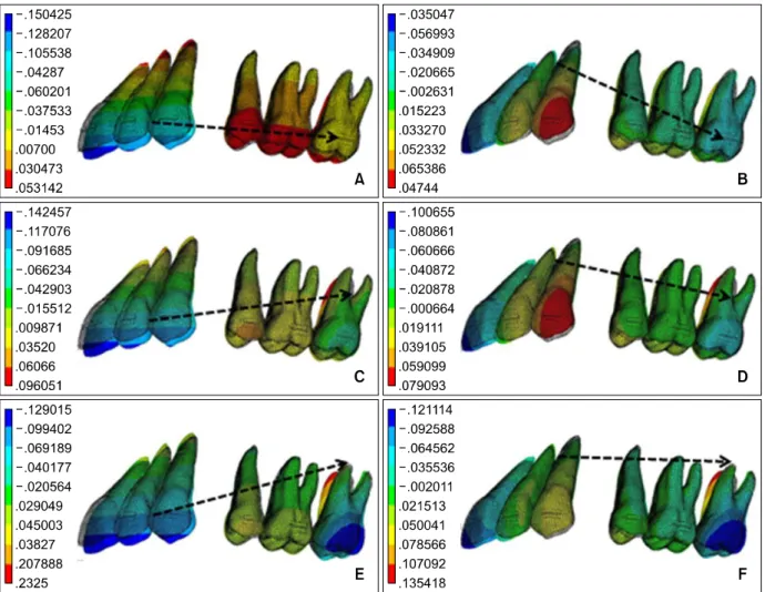
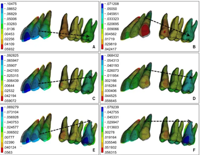
Fig 2. Contour plot of frontal displacement at each condition. A, Length of lever arm is 0 mm and position of retraction hook is at the bracket of the 2nd molar; B, length of lever arm is 20 mm and position of retraction hook is at the bracket of the 2nd molar; C, length of lever arm is 0 mm and position of retraction hook is at the furcation of the 2nd molar; D, length of lever arm is 20 mm and position of retraction hook is at the furcation of the 2nd molar; E, length of lever arm is 0 mm and position of retraction hook is at the root apex of the 2nd molar; F, length of lever arm is 20 mm and position of retraction hook is at the root apex of the 2nd molar.
체였으며, 총절점수는 253,556개였고 모델의 기저 면, 즉 구개골 기저부에 대해서는 x, y, z 방향으로 변위를 제한하였다. 기준 좌표계는 양측 중절치의 절단연을 이은 선의 중점을 원점으로 하여, 측방 (협설측) 방향을 x축, 전후방(순설측) 방향을 y축, 상하 방향(절단치은측)을 z축으로 정하였다. 즉 x축 에서는 우측 협측 방향이, y축에서는 순측 방향이, z축에서는 치근첨 방향이 + 값이다 (Fig 1C).
치아의 초기 이동 반응을 비교하기 위하여 치근 면의 von Mises 응력분포를 contour plot으로 관찰하 였고, 전치부는 절단연의 중점과 치근첨, 견치는 치 관첨과 치근첨, 소구치부는 협측 교두첨과 치근첨,
대구치부는 근심협측 교두첨과 치근첨에 위치한 절 점의 x, y, z축 좌표를 구하여 각각의 변위량을 계산 하였다.
연구성적
각각의 실험 조건을 유한요소 모델에 적용하고 전치부에서는 각 치아의 절단연과 치근첨, 제2소구 치는 협측 교두첨 및 협측 치근첨, 대구치부는 근심 협측 교두첨 및 치근첨의 좌표를 구하고 이동거리 를 계측하여 x, y, z 각 방향으로의 이동량을 분석하 였다.
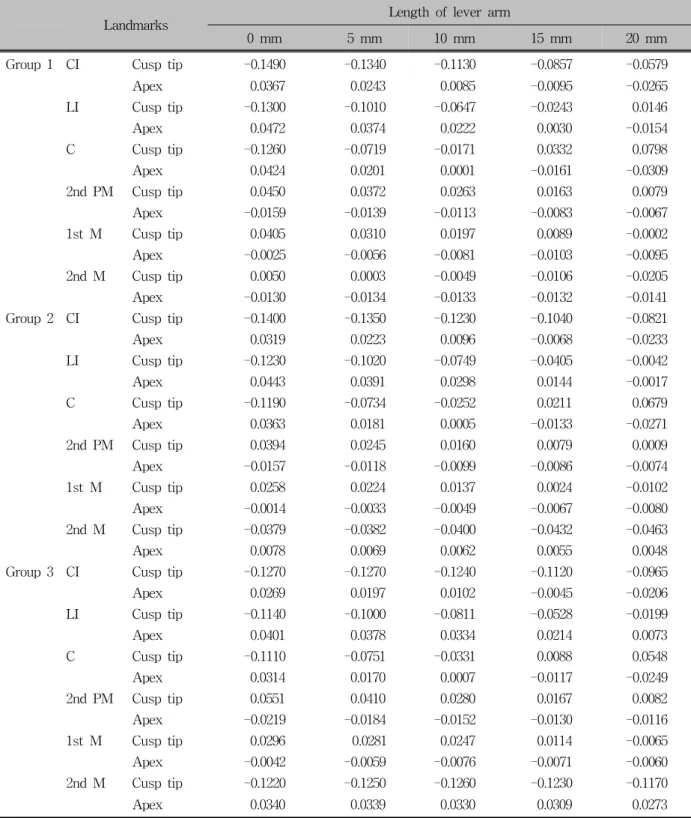
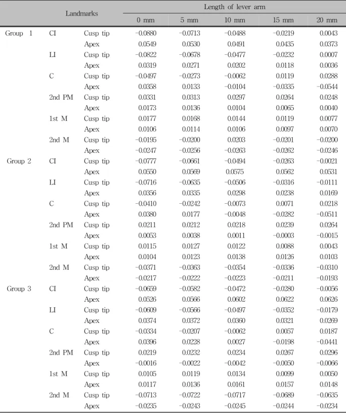
Landmarks Length of lever arm
0 mm 5 mm 10 mm 15 mm 20 mm
Group 1 CI Cusp tip -0.1490 -0.1340 -0.1130 -0.0857 -0.0579
Apex 0.0367 0.0243 0.0085 -0.0095 -0.0265
LI Cusp tip -0.1300 -0.1010 -0.0647 -0.0243 0.0146
Apex 0.0472 0.0374 0.0222 0.0030 -0.0154
C Cusp tip -0.1260 -0.0719 -0.0171 0.0332 0.0798
Apex 0.0424 0.0201 0.0001 -0.0161 -0.0309
2nd PM Cusp tip 0.0450 0.0372 0.0263 0.0163 0.0079
Apex -0.0159 -0.0139 -0.0113 -0.0083 -0.0067
1st M Cusp tip 0.0405 0.0310 0.0197 0.0089 -0.0002
Apex -0.0025 -0.0056 -0.0081 -0.0103 -0.0095
2nd M Cusp tip 0.0050 0.0003 -0.0049 -0.0106 -0.0205
Apex -0.0130 -0.0134 -0.0133 -0.0132 -0.0141
Group 2 CI Cusp tip -0.1400 -0.1350 -0.1230 -0.1040 -0.0821
Apex 0.0319 0.0223 0.0096 -0.0068 -0.0233
LI Cusp tip -0.1230 -0.1020 -0.0749 -0.0405 -0.0042
Apex 0.0443 0.0391 0.0298 0.0144 -0.0017
C Cusp tip -0.1190 -0.0734 -0.0252 0.0211 0.0679
Apex 0.0363 0.0181 0.0005 -0.0133 -0.0271
2nd PM Cusp tip 0.0394 0.0245 0.0160 0.0079 0.0009
Apex -0.0157 -0.0118 -0.0099 -0.0086 -0.0074
1st M Cusp tip 0.0258 0.0224 0.0137 0.0024 -0.0102
Apex -0.0014 -0.0033 -0.0049 -0.0067 -0.0080
2nd M Cusp tip -0.0379 -0.0382 -0.0400 -0.0432 -0.0463
Apex 0.0078 0.0069 0.0062 0.0055 0.0048
Group 3 CI Cusp tip -0.1270 -0.1270 -0.1240 -0.1120 -0.0965
Apex 0.0269 0.0197 0.0102 -0.0045 -0.0206
LI Cusp tip -0.1140 -0.1000 -0.0811 -0.0528 -0.0199
Apex 0.0401 0.0378 0.0334 0.0214 0.0073
C Cusp tip -0.1110 -0.0751 -0.0331 0.0088 0.0548
Apex 0.0314 0.0170 0.0007 -0.0117 -0.0249
2nd PM Cusp tip 0.0551 0.0410 0.0280 0.0167 0.0082
Apex -0.0219 -0.0184 -0.0152 -0.0130 -0.0116
1st M Cusp tip 0.0296 0.0281 0.0247 0.0114 -0.0065
Apex -0.0042 -0.0059 -0.0076 -0.0071 -0.0060
2nd M Cusp tip -0.1220 -0.1250 -0.1260 -0.1230 -0.1170
Apex 0.0340 0.0339 0.0330 0.0309 0.0273
Group 1, Retraction arm was positioned at the level of the 2nd molar bracket; Group 2, retraction arm was positioned at the furcation level of 2nd molar; Group 3, retraction arm was positioned at the root apex of 2nd molar; CI, central incisors; LI, lateral incisors; C, canine; PM, premolars; M, molars.
Table 2. Amount of frontal displacement along the Y-axis for each group
Fig 3. Contour plot of vertical displacement at each condition. A, Length of lever arm is 0 mm and position of re- traction hook is at the bracket of the 2nd molar; B, length of lever arm is 20 mm and position of retraction hook is at the bracket of the 2nd molar; C, length of lever arm is 0 mm and position of retraction hook is at the furcation of the 2nd molar; D, length of lever arm is 20 mm and position of retraction hook is at the furcation of the 2nd molar;
E, length of lever arm is 0 mm and position of retraction hook is at the root apex of the 2nd molar; F, length of lever arm is 20 mm and position of retraction hook is at the root apex of the 2nd molar.
치아의 전후방 이동양상(Frontal displacement)
상악 측절치와 견치 사이에 레버 암의 길이를 달 리 하여 200 gm의 교정력을 적용한 결과 제2대구치 의 견인 훅의 위치에 관계없이 레버 암의 길이가 0 mm, 5 mm, 10 mm인 경우에 상악 전치 절단연의 설 측, 치근첨의 순측 변위가 관찰되었고, 레버 암의 길이가 15 mm, 20 mm인 경우 전치 절단연과 치근 첨이 공히 설측 변위되는 양상을 보였다. 치근첨의 설측 변위는 20 mm인 경우 (Fig 2B, 2D, 2F) 가장 크게 나타났다. 레버 암의 길이가 0 mm, 견인 훅의 위치가 제2대구치의 설측 브라켓의 높이에 있는 경
우 (Fig 2A) 제2소구치와 제1, 2대구치는 치관의 근 심 변위 양상을 보인다. 반면, 견인 훅의 위치가 제2 대구치의 치근 분지부 및 치근첨에 있는 경우 (Fig 2C - 2F) 대구치 치관의 원심 변위 양상을 볼 수 있 다 (Table 2).
치아의 수직 이동양상(Vertical displacement)
레버 암의 길이가 짧을수록 (Fig 3A, 3C, 3E) 중 절치와 측절치의 정출 양상이 심하고, 특히 후방 견 인 훅의 위치가 구치 치근첨에 있는 경우 제2소구 치의 함입과 제2대구치의 근심협측 교두의 정출 양
Landmarks Length of lever arm
0 mm 5 mm 10 mm 15 mm 20 mm
Group 1 CI Cusp tip -0.0880 -0.0713 -0.0488 -0.0219 0.0043
Apex 0.0549 0.0530 0.0491 0.0435 0.0373
LI Cusp tip -0.0822 -0.0678 -0.0477 -0.0232 0.0007
Apex 0.0319 0.0271 0.0202 0.0118 0.0036
C Cusp tip -0.0497 -0.0273 -0.0062 0.0119 0.0288
Apex 0.0358 0.0133 -0.0104 -0.0335 -0.0544
2nd PM Cusp tip 0.0331 0.0313 0.0297 0.0264 0.0248
Apex 0.0173 0.0136 0.0104 0.0065 0.0040
1st M Cusp tip 0.0177 0.0168 0.0144 0.0119 0.0077
Apex 0.0106 0.0114 0.0106 0.0097 0.0070
2nd M Cusp tip -0.0195 -0.0200 0.0203 -0.0201 -0.0200
Apex -0.0247 -0.0256 -0.0263 -0.0262 -0.0246
Group 2 CI Cusp tip -0.0777 -0.0661 -0.0494 -0.0263 -0.0021
Apex 0.0550 0.0569 0.0575 0.0562 0.0531
LI Cusp tip -0.0716 -0.0635 -0.0506 -0.0316 -0.0111
Apex 0.0356 0.0335 0.0298 0.0238 0.0169
C Cusp tip -0.0410 -0.0242 -0.0073 0.0071 0.0218
Apex 0.0380 0.0177 -0.0048 -0.0282 -0.0511
2nd PM Cusp tip 0.0211 0.0212 0.0218 0.0239 0.0264
Apex 0.0053 0.0038 0.0011 -0.0003 -0.0015
1st M Cusp tip 0.0115 0.0127 0.0122 0.0088 0.0043
Apex 0.0104 0.0123 0.0138 0.0126 0.0103
2nd M Cusp tip -0.0371 -0.0363 -0.0354 -0.0336 -0.0310
Apex -0.0217 -0.0222 -0.0223 -0.0211 -0.0193
Group 3 CI Cusp tip -0.0659 -0.0582 -0.0472 -0.0280 -0.0056
Apex 0.0526 0.0566 0.0602 0.0622 0.0626
LI Cusp tip -0.0609 -0.0566 -0.0497 -0.0352 -0.0179
Apex 0.0374 0.0372 0.0360 0.0321 0.0269
C Cusp tip -0.0334 -0.0207 -0.0062 0.0057 0.0187
Apex 0.0396 0.0228 0.0027 -0.0198 -0.0441
2nd PM Cusp tip 0.0219 0.0232 0.0234 0.0267 0.0296
Apex -0.0016 -0.0022 -0.0042 -0.0050 -0.0066
1st M Cusp tip 0.0105 0.0119 0.0134 0.0099 0.0050
Apex 0.0117 0.0136 0.0161 0.0157 0.0148
2nd M Cusp tip -0.0713 -0.0722 -0.0717 -0.0689 -0.0635
Apex -0.0235 -0.0243 -0.0245 -0.0244 -0.0234
Group 1, Retraction arm was positioned at the level of the 2nd molar bracket; Group 2, retraction arm was positioned at the furcation level of 2nd molar; Group 3, retraction arm was positioned at the root apex of 2nd molar; CI, central incisors; LI, lateral incisors; C, canine; PM, premolars; M, molars.
Table 3. Amount of vertical displacement along Z-axis for each group
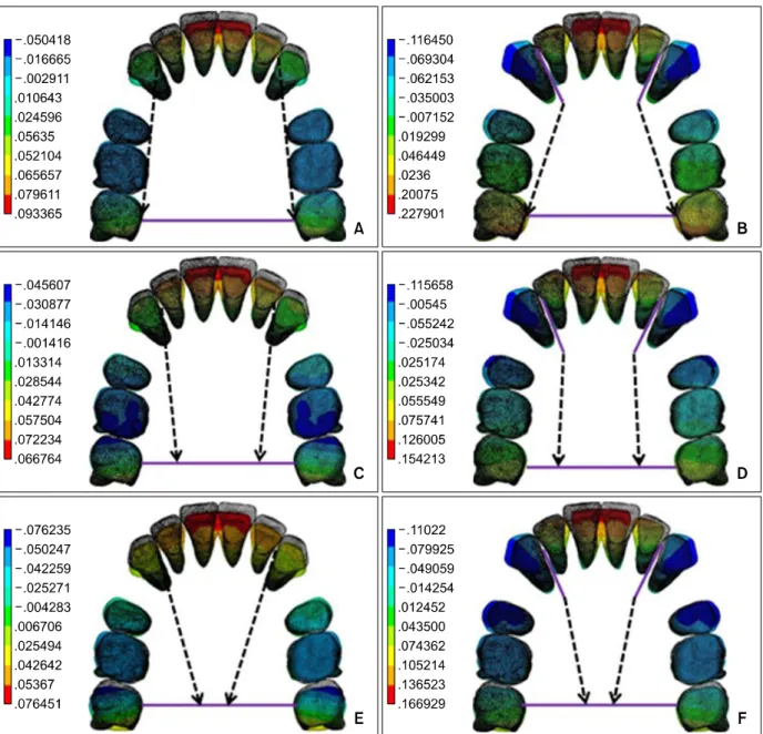
Fig 4. Contour plot of lateral displacement at each condition. A, Length of lever arm is 0 mm and position of retraction hook is at the bracket of the 2nd molar; B, length of lever arm is 20 mm and position of retraction hook is at the bracket of the 2nd molar; C, length of lever arm is 0 mm and position of retraction hook is at the furcation of the 2nd molar; D, length of lever arm is 20 mm and position of retraction hook is at the furcation of the 2nd molar; E, length of lever arm is 0 mm and position of retraction hook is at the root apex of the 2nd molar; F, length of lever arm is 20 mm and position of retraction hook is at the root apex of the 2nd molar.
상이 일어났다. 반면에, 레버 암의 길이가 길수록 전치부의 정출 양상은 미약하며, 후방 견인 훅의 위 치가 구치의 설측 브라켓 높이에 있는 경우 (Fig 3B) 견치의 함입 양상이 관찰되었다 (Fig 3, Table 3).
치아의 측방 이동양상(Lateral displacement)
레버 암의 길이가 짧을수록 측방 이동 양상에는 변화가 없으나, 레버 암의 길이가 길수록 견치의 협 측 방향으로의 전위 양상이 증가하였다. 특히 레버 암의 길이가 20 mm인 경우, 구치 견인 훅의 위치가
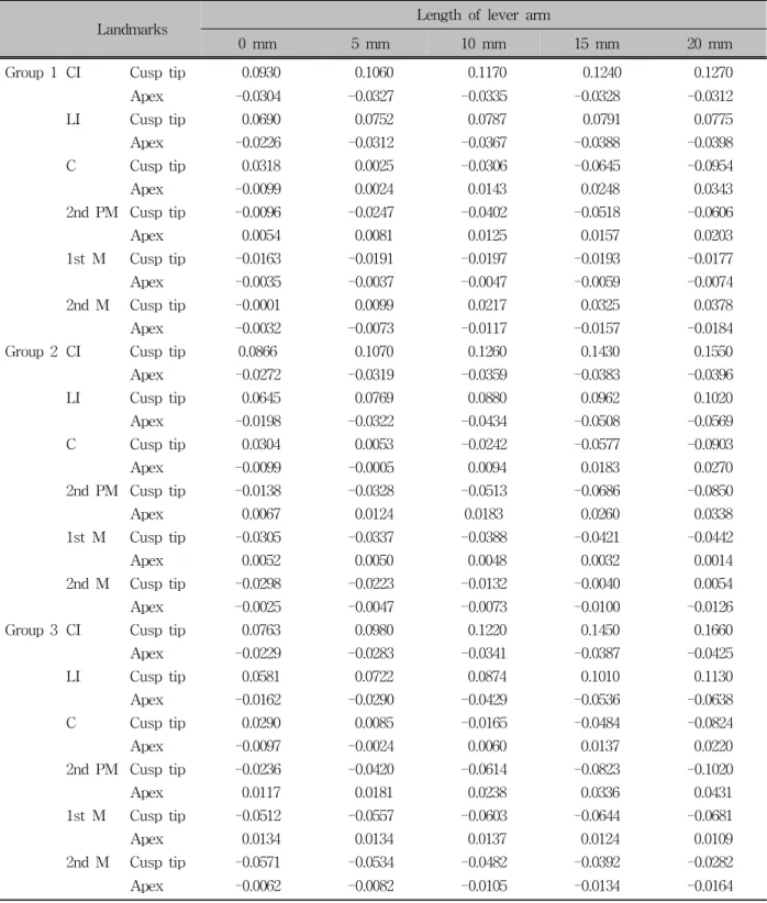
Landmarks Length of lever arm
0 mm 5 mm 10 mm 15 mm 20 mm
Group 1 CI Cusp tip 0.0930 0.1060 0.1170 0.1240 0.1270
Apex -0.0304 -0.0327 -0.0335 -0.0328 -0.0312
LI Cusp tip 0.0690 0.0752 0.0787 0.0791 0.0775
Apex -0.0226 -0.0312 -0.0367 -0.0388 -0.0398
C Cusp tip 0.0318 0.0025 -0.0306 -0.0645 -0.0954
Apex -0.0099 0.0024 0.0143 0.0248 0.0343
2nd PM Cusp tip -0.0096 -0.0247 -0.0402 -0.0518 -0.0606
Apex 0.0054 0.0081 0.0125 0.0157 0.0203
1st M Cusp tip -0.0163 -0.0191 -0.0197 -0.0193 -0.0177
Apex -0.0035 -0.0037 -0.0047 -0.0059 -0.0074
2nd M Cusp tip -0.0001 0.0099 0.0217 0.0325 0.0378
Apex -0.0032 -0.0073 -0.0117 -0.0157 -0.0184
Group 2 CI Cusp tip 0.0866 0.1070 0.1260 0.1430 0.1550
Apex -0.0272 -0.0319 -0.0359 -0.0383 -0.0396
LI Cusp tip 0.0645 0.0769 0.0880 0.0962 0.1020
Apex -0.0198 -0.0322 -0.0434 -0.0508 -0.0569
C Cusp tip 0.0304 0.0053 -0.0242 -0.0577 -0.0903
Apex -0.0099 -0.0005 0.0094 0.0183 0.0270
2nd PM Cusp tip -0.0138 -0.0328 -0.0513 -0.0686 -0.0850
Apex 0.0067 0.0124 0.0183 0.0260 0.0338
1st M Cusp tip -0.0305 -0.0337 -0.0388 -0.0421 -0.0442
Apex 0.0052 0.0050 0.0048 0.0032 0.0014
2nd M Cusp tip -0.0298 -0.0223 -0.0132 -0.0040 0.0054
Apex -0.0025 -0.0047 -0.0073 -0.0100 -0.0126
Group 3 CI Cusp tip 0.0763 0.0980 0.1220 0.1450 0.1660
Apex -0.0229 -0.0283 -0.0341 -0.0387 -0.0425
LI Cusp tip 0.0581 0.0722 0.0874 0.1010 0.1130
Apex -0.0162 -0.0290 -0.0429 -0.0536 -0.0638
C Cusp tip 0.0290 0.0085 -0.0165 -0.0484 -0.0824
Apex -0.0097 -0.0024 0.0060 0.0137 0.0220
2nd PM Cusp tip -0.0236 -0.0420 -0.0614 -0.0823 -0.1020
Apex 0.0117 0.0181 0.0238 0.0336 0.0431
1st M Cusp tip -0.0512 -0.0557 -0.0603 -0.0644 -0.0681
Apex 0.0134 0.0134 0.0137 0.0124 0.0109
2nd M Cusp tip -0.0571 -0.0534 -0.0482 -0.0392 -0.0282
Apex -0.0062 -0.0082 -0.0105 -0.0134 -0.0164
Group 1, Retraction arm was positioned at the level of the 2nd molar bracket; Group 2, retraction arm was positioned at the furcation level of 2nd molar; Group 3, retraction arm was positioned at the root apex of 2nd molar; CI, central incisors; LI, lateral incisors; C, canine; PM, premolars; M, molars.
Table 4. Amount of lateral displacement along X-axis for each group
Fig 5. Comparison of the position of lever arm and CR of anterior teeth from other studies
35: (blue) - study by Jeong et al
35showing center of resistance of six an- terior teeth; (green) - study by Vanden Bulcke et al
31showing center of resistance of four anterior teeth;
(purple) - study by Vanden Bulcke et al
31showing center of resistance of six anterior teeth. CR, Center of resistance; CEJ, cemento enamel junction.
TPA의 구개 중앙 측에 있을 때 (Fig 4F)보다 TPA 의 가장자리 측에 있을 때 (Fig 4B) 더 많은 양의 치 관 전위 양상을 보였다 (Fig 4, Table 4).
von Mises 응력 분포 양상(g/mm2)
치아에 미치는 응력분포 양상은 치아의 이동량이 많은 전방부의 치근막에 주로 많이 분포하였다. 구 치부로 갈수록 감소하는 양상을 보이며 비교적 치 근면 전체의 치근막에 고르게 분포하였다. 후방 견 인 훅이 구치의 설측 브라켓 높이에 있는 경우 중절 치 치경부의 치근막에 집중되어 나타났고 나머지 다른 치아에는 골고루 분포하였다. 후방견인 훅이 구치 치근 분지부에 있는 경우 중절치 치경부의 치 근막과 제2대구치 구개측 치근의 치근막에, 후방 견 인 훅이 구치 치근첨에 있는 경우 제2대구치의 구 개측 치근막에 주로 분포하였다.
고찰
공간 폐쇄를 위한 설측 교정치료 시 Alexander 등18 은 전치부의 토크 조절을 위해서 굵은 호선을 사용 하는 것이 유리하며, 과다한 힘으로 견인 시 소구치 가 협측으로 경사되고 최후방 구치는 구개측 치근 을 중심으로 원심 회전되는 transverse bowing 현상 을 방지하기 위해 TPA를 함께 사용하여야 한다고 하였다. Smith 등19은 제2대구치에도 장치를 부착하 고 연속호선을 삽입할 것을 추천하였다. 그러나, 임 상적으로 굵은 호선을 사용하여 전치의 토크를 조 절하는 것은 한계가 있으며, 전치의 전후방적 이동 을 조절할 수 있는 레버 암 메카닉스를 적용하여 그 한계를 넘을 수 있는가에 대한 연구가 필요하였다.
설측 교정 치료에서 전치부의 후방 견인 시 순측 교정 치료에 비해 적은 양의 모멘트가 발생하기 위 해서는 힘의 작용점을 전치부의 저항중심에 가깝게 적용해야 하며, 저항중심이란 단일한 힘을 물체에 가할 때 이 물체가 평행이동(translation) 될 수 있는 힘의 적용 부위를 말한다.20 이에 본 연구에서 치아 의 변화양상을 관찰한 결과 레버 암의 길이가 20 mm인 경우 전치의 치체이동에 가까운 변위 양상을 관찰할 수 있었다. 이 지점은 본 연구의 유한요소모 델에서 레버 암의 각도를 교합평면에 대하여 45도 로 설정하였으므로 중절치의 절단연으로부터 18.5 mm 떨어진 지점이며 저항중심 상방에 해당한다 (Fig 5). Davidian21은 상악 중절치의 저항중심을 치
근단측으로부터 51 - 61%라 보고하였고, Burstone과 Koenig22은 치근길이의 치경측 40%에 위치한다고 보고하였다. Vanden Bulcke 등23은 상악 4전치의 저 항중심은 전후방적으로 견치 원심면, 수직적으로 중절치간 치조골 상연에서 약 5 mm 하방에 존재하 고 상악 6전치의 저항중심은 전후방적으로 제1소구 치의 원심면, 수직적으로는 중절치간 치조골 상연 에서 약 7 mm 하방에 존재한다고 하였으며, 국내연 구로 Woo와 Park,24 Park과 Sohn25도 이와 유사한 결 과를 발표하였다. Lee와 Chung26은 상악 제1대구치 의 저항중심이 trifurcation으로부터 교합면쪽으로 경 미하게 떨어져 있다고 하였다. 최근 Jeong 등27의 연 구에서 상악 4전치군의 저항중심은 상악 중절치 절 단연으로부터 치근방향 13.5 mm, 후방 12.0 mm, 상 악 6전치군은 상악 중절치 절단연으로부터 치근방 향 13.5 mm, 후방 14.0 mm에 위치하였으며 상악 전 치열군의 저항중심은 상악 중절치 절단연으로부터 치근방향 11.0 mm, 후방 26.5 mm에 위치한다고 보 고하였다. 이와 같이 타 연구에서 나타난 저항중심 보다 높은 지점에서 전치의 치체이동에 가까운 변 위가 일어난 것은 아마도 레버 암이 상방 및 중앙부 로 올라가며 경사지므로 설측에서 예상하지 못한 측방력이 발생하였고, 그로 인해 타 연구의 저항중 심 위치인 레버 암이 짧은 경우에서는 전치의 설측 경사가 나타난 것으로 보인다.
본 연구에서 전치의 이동은 후방 힘의 작용선의 위치에 무관하게 레버 암의 길이가 20 mm인 경우 공히 전치의 절단연과 치근첨의 후방변위를 나타내 나 견치는 이와 상이하게 치관의 전방 변위, 치근의
후방변위를 보인다 (Table 2). 일반적으로 알려진 호 선의 transverse bowing에 의해 동일 분절 내에서도 변위 양상이 다르게 나타남은 3차원 유한요소분석 을 통해 알 수 있는 유용한 정보라 생각되며 이러한 견치의 변위는 동일한 레버 암의 길이에서 견인력 의 각도가 외측으로 향할수록 증가하므로 역시 레 버 암에 의해 외측으로의 leverage 효과가 나타나는 것으로 생각된다 (Fig 4).
따라서 임상적 적용 시 초기 변화 후 호선의 회 복을 기다리거나 compensation bend를 부여하는 등 의 대책이 필요할 것이다. 또한 본 연구는 3차원적 유한요소 모델을 통해 알 수 있듯이 단순히 직선형 의 레버 암의 길이를 연장하는 것만이 치아 이동 형 태의 결정요소는 아니며, 레버 암의 구조를 강화하 는 것이 필요함을 보여준다. 따라서 본 결과에서와 같이 굵은 선상의 레버 암을 저항중심보다 더 높게 연장하거나 supporting strut을 추가하는 등의 노력이 필요할 것으로 생각된다. 이러한 부가적 구조의 역 할 및 이에 따른 변위 양상의 연구는 후속하여 진행 되어야 할 것이다.
본 연구에서 제작한 유한요소모델의 치주인대의 탄성계수는 치아 및 골의 탄성계수에 비해 수만 배 작다는 것에 이견이 없으나 실험상 물성의 정의 및 탄성의 정도에 대해서는 믿을 만한 수치를 찾기 어 렵다. 치주인대의 물성에 대해서는 bilinear model 을 이용하거나 단순히 등질, 등방의 단일값을 정의 하기도 한다.15,16 또한 탄성계수는 0.01 MPa에서 100 MPa까지 매우 다양하게 정의되었다.28 Andersen 등29 은 생검 모델에서의 실험적인 반복재현 계산법을 통해 치주인대에 대해 0.07 MPa의 탄성계수와 0.49 의 Poisson’s ratio를 제시하였으나 물성의 정의와 구 속조건이 결과에 유의할 만한 영향을 미치지 않는 다고 하였다. 그러므로 본 연구에서는 문헌상 유사 한 모델링을 보이는 Tanne 등15 및 Sung 등16에 따라 등질, 등방성의 단일 탄성계수를 갖는 물질로 정의 하였다. 치근면 응력 분포를 관찰하기 위하여 사용 한 von Mises stress는 모든 방향의 응력 성분을 하 나의 대표값으로 대치한 것으로 주 응력은 각각 공 간좌표 상에서 나오는 6개의 응력 성분으로 계산된 다. Cobo 등30에 의하면 치아와 그 주위조직의 물리 적 성질이 아직 완전히 밝혀지지 않았기 때문에 연 구에서 얻어진 응력의 값은 주의 깊게 해석되어야 한다고 했다. 본 모델에서는 주어진 힘에 의한 초기 반응만을 관찰한 것이며, 힘의 제공은 일시에 가해 지는 것으로 가정되므로 힘의 크기에 따라 단지 변
위량에만 영향을 주며 치아 변위 양상에 대해서는 변화가 없음을 확인하였다. 그러나 이러한 초기 변 화가 시간에 따른 변위 양상을 직접적으로 재현하 는 데는 한계가 있을 것으로 보이며 이를 위해 dy- namic analysis 등의 특이한 기법을 이용하여야 하나 현재까지 신뢰할 만한 기법이 도입되지 않은 상태 이다. 따라서 추후에 이러한 문제점들을 보완하고 임상적, 세포학적 및 생화학적인 연구가 뒷받침된 다면 이를 임상에서 활용하는 데 많은 도움이 될 것 이다.
결론
설측 교정 시 레버 암의 길이와 구치 견인 훅의 위치를 달리 하여 상악 6전치를 견인할 때 나타나 는 치아 변위를 3차원적 유한요소해석을 통하여 관 찰한 결과 lever arm의 길이가 15 mm, 20 mm인 경 우 전치 절단연과 치근첨의 설측 변위가 유도되었 고 본 실험의 조건 중 20 mm에서 치근첨의 설측 변 위는 최대로 나타났다. 구치부 견인 훅이 치근첨에 있을 때 대구치 치관은 원심 방향으로 변위되었다.
레버 암의 길이가 20 mm인 경우 전치부의 정출은 미약하였고 견치 치관은 협측 방향으로 전위되었 다. 이 때 구치부 견인 훅의 위치가 TPA의 구개 중 앙 측에 있을 때보다 TPA의 가장자리 측에 있을 때 더 많은 양의 치관 전위 양상을 보였다. 이상의 결 과를 토대로 설측 장치를 이용한 상악 6전치의 후 방 견인 시 레버 암의 길이가 길고 구치부 견인 훅 의 위치가 구개 중앙부에 있을 때 전치부 절단연 (incisal edge)의 정출 없이 견치의 측방 전위 및 전 치부 절단연과 치근첨의 설측 변위가 공히 나타남 을 알 수 있었다.
참고문헌
1. Liang W, Rong Q, Lin J, Xu B. Torque control of the maxil- lary incisors in lingual and labial orthodontics: a 3-dimensional finite element analysis. Am J Orthod Dentofacial Orthop 2009;135:316-22.
2. Kucher G, Weiland FJ, Bantleon HP. Modified lingual lever arm technique. J Clin Orthod 1993;27:18-22.
3. Park YC, Choy K, Lee JS, Kim TK. Lever-arm mechanics in lingual orthodontics. J Clin Orthod 2000;34:601-5.
4. Sia S, Koga Y, Yoshida N. Determining the center of resist- ance of maxillary anterior teeth subjected to retraction forces in sliding mechanics. An in vivo study. Angle Orthod 2007;77:
999-1003.
5. Lewis G, Kambhampati S, Roussel S. Effect of the archwire
slot profile on the performance of bonded orthodontic brackets.
Biomed Mater Eng 1997;7:205-12.
6. Burstone CJ, Pryputniewicz RJ. Holographic determination of centers of rotation produced by orthodontic forces. Am J Orthod 1980;77:396-409.
7. Pedersen E, Andersen K, Melsen B. Tooth displacement ana- lysed on human autopsy material by means of a strain gauge technique. Eur J Orthod 1991;13:65-74.
8. Reimann S, Keilig L, Jäger A, Bourauel C Biomechanical fi- nite-element investigation of the position of the centre of re- sistance of the upper incisors. Eur J Orthod 2007;29:219-24.
9. Kim CN, Sung JH, Kyung HM. Three-dimensional finite ele- ment analysis of initial tooth displacement according to force application point during maxillary six anterior teeth retraction using skeletal anchorage. Korean J Orthod 2003;33:339-50.
10. Andrews LF. The six keys to normal occlusion. Am J Orthod 1972;62:296-309.
11. Coolidge E. The thickness of the human periodontal mem- brane. J Am Dent Assoc 1937;24:1260-5.
12. Kronfeld R. Histologic study of the influence of function on the human periodontal membrane. J Am Dent Assoc 1931;18:
1242-72.
13. Andrews LF. The six keys to optimal occlusion. In: Andrews LF editor. Straight wire: the concept and appliance. San Diego:
LA Wells; 1989. p. 13-24.
14. Cook SD, Weinstein AM, Klawitter JJ. A three-dimensional fi- nite element analysis of a porous rooted Co-Cr-Mo alloy den- tal implant. J Dent Res 1982;61:25-9.
15. Tanne K, Sakuda M, Burstone CJ. Three-dimensional finite el- ement analysis for stress in the periodontal tissue by orthodontic forces. Am J Orthod Dentofacial Orthop 1987;92:499-505.
16. Sung SJ, Baik HS, Moon YS, Yu HS, Cho YS. A comparative evaluation of different compensating curves in the lingual and labial techniques using 3D FEM. Am J Orthod Dentofacial Orthop 2003;123:441-50.
17. Bennett JC, McLaughlin RP. Controlled space closure with a preadjusted appliance system. J Clin Orthod 1990;24:251-60.
18. Alexander CM, Alexander RG, Gorman JC, Hilgers JJ, Kurz C, Scholz RP, et al. Lingual orthodontics: a status report. Part
5. Lingual mechanotherapy. J Clin Orthod 1983;17:99-115.
19. Smith JR, Gorman JC, Kurz C, Dunn RM. Keys to success in lingual therapy. Part 1. J Clin Orthod 1986;20:252-61.
20. Smith RJ, Burstone CJ. Mechanics of tooth movement. Am J Orthod 1984;85:294-307.
21. Davidian EJ. Use of a computer model to study the force dis- tribution on the root of the maxillary central incisor. Am J Orthod 1971;59:581-8.
22. Burstone CJ, Koenig HA. Optimizing anterior and canine retraction. Am J Orthod 1976;70:1-19.
23. Vanden Bulcke MM, Burstone CJ, Sachdeva RC, Dermaut LR.
Location of the centers of resistance for anterior teeth during retraction using the laser reflection technique. Am J Orthod Dentofacial Orthop 1987;91:375-84.
24. Woo JY, Park YC Experimental study of the vertical location of the centers of resistance for maxillary anterior teeth during retraction using the laser reflection technique. Korean J Orthod 1993;23:375-89.
25. Park GH, Sohn BW. The center of resistance of the maxillary anterior segment in the horizontal plane during intrusion by us- ing laser reflection technique. Korean J Orthod 1993;23:
619-31.
26. Lee HK, Chung KR. The vertical location of the center of re- sistance for maxillary six anterior teeth during retraction using three dimensional finite element analysis. Korean J Orthod 2001;31:425-38.
27. Jeong GM, Sung SJ, Lee KJ, Chun YS, Mo SS. Finite-element investigation of the center of resistance of the maxillary dentition. Koran J Orthod 2009;39:83-94.
28. Tanne K, Yoshida S, Kawata T, Sasaki A, Knox J, Jones ML.
An evaluation of the biomechanical response of the tooth and periodontium to orthodontic forces in adolescent and adult subjects. Br J Orthod 1998;25:109-15.
29. Andersen KL, Pedersen EH, Melsen B. Material parameters and stress profiles within the periodontal ligament. Am J Orthod Dentofacial Orthop 1991;99:427-40.
30. Cobo J, Argüelles J, Puente M, Vijande M. Dentoalveolar stress from bodily tooth movement at different levels of bone loss. Am J Orthod Dentofacial Orthop 1996;110:256-62.
Finite element analysis of effectiveness of lever arm in lingual sliding mechanics
Kyeong-Hee Kim, DDS, MS, a Kee-Joon Lee, DDS, MSD, PhD, b Jung-Yul Cha, DDS, MSD, PhD, c Young-Chel Park, DDS, MSD, PhD d
Objective: The aim of this study was to conduct three-dimensional finite element analysis of individual tooth dis- placement and stress distribution when a posterior retraction force of 200 g was applied at different positions of the retraction hook on the transpalatal arch (TPA) of a molar, and over different lengths of the lever arm on the maxillary anterior teeth in lingual orthodontics. Methods: A three-dimensional finite element model, including the entire upper dentition, periodontal ligaments, and alveolar bones, was constructed on the basis of a sample (Nissan Dental Product, Kyoto, Japan) survey of Asian adults. Individual movement of the incisal edge and root apex was estimated along the x-, y-, and z-coordinates to analyze tooth displacement and von Mises stress distribution. Results: When the length of the lever arm was 15 mm and 20 mm, the incisal edge and root apex of the anterior teeth was displaced lingually, with a maximum lingual displacement at the lever arm length of 20 mm. When the posterior retraction hook was on the root apex, the molars showed distal displacement. When the length of the lever arm was 20 mm, anterior extrusion was reduced and the crown of the canine displaced toward the buccal side, in which case, the retraction hook was on the edge, rather than at the center, of the TPA. Conclusions: The results of the analysis showed that when 6 anterior teeth were retracted posteriorly, later- al displacement of the canine and lingual displacement of the incisal edge and root apex of the anterior teeth occur without the extrusion of the anterior segment when the length of the lever arm is longer, and the posterior retraction hook is in the midpalatal area. (Korean J Orthod 2011;41(5):324-336)
Key words: Lingual orthodontics, Sliding mechanics, Lever arm, Finite element analysis
aPrivate Practice.
bAssociate Professor, cAssistant Professor, dProfessor, Department of Orthodontics, College of Dentistry, Yonsei University.
Corresponding author: Young-Chel Park.
Department of Orthodontics, College of Dentistry, Yonsei University, 250 Seongsanno, Seodaemun-gu, Seoul 120-752, Korea.
+82 2 2228 3103; e-mail, [email protected].
Received November 24, 2010; Last Revision May 10, 2011; Accepted May 13, 2011.
*Supported by the grant of cranio-facial deformity research institute at College of Dentistry, Yonsei University.